
 Submit a Paper
 Propose a Special lssue
 Open Access
ARTICLE

Computer Modeling of Pipeline Repair Reinforcement with Composite Bandages
1 Mechanical Engineering Department, Petroleum-Gas University of Ploieşti, Ploiesti, Romania
2 Department of Mathematical Modeling and Intelligent Computing in Engineering, NTU Kharkov Polytechnic Institute, Kharkov, Ukraine
* Corresponding Author: Maria Tănase. Email:
(This article belongs to the Special Issue: Advances in Numerical Modeling of Composite Structures and Repairs)
Computer Modeling in Engineering & Sciences 2026, 146(2), 9 https://doi.org/10.32604/cmes.2026.078844
Received 09 January 2026; Accepted 26 January 2026; Issue published 26 February 2026
 View Full Text
 Download PDF
Abstract
The increasing occurrence of corrosion-related damage in steel pipelines has led to the growing use of composite-based repair techniques as an efficient alternative to traditional replacement methods. Computer modeling and structural analysis were performed for the repair reinforcement of a steel pipeline with a composite bandage. A preliminary analysis of possible contact interaction schemes was implemented based on the theory of cylindrical shells, taking into account transverse shear deformations. The finite element method was used for a detailed study of the stress state of the composite bandage and the reinforced section of the pipeline. The limit state of the reinforced section was assessed based on the von Mises criterion for steel and the Tsai-Wu criterion for composites. The effectiveness of the repair was demonstrated on a pipeline whose wall thickness had decreased by 20% as a result of corrosion damage. At a nominal pressure of P = 6 MPa, the maximum normal stress in the weakened area reached 381 MPa. The installation of a composite bandage reduced this stress to 312 MPa, making the repaired section virtually as strong as the undamaged pipeline. Due to the linearity of the problem, the results obtained can be easily used to find critical internal pressure values.Keywords
Oil and gas play a key role in the modern economy and energy sector, as they account for more than 50% of global energy consumption. Main pipelines are of strategic importance for the long-distance transportation of oil, gas, and petroleum products, ensuring the stability of energy systems and national economies. During long-term operation of underground and underwater pipeline systems, defects form in certain sections due to corrosion processes and adhesive wear, leading to a decrease in the strength characteristics of the structure. Repair work using welding technologies requires a complete shutdown of the working medium for a significant period of time, which causes significant economic losses and increases the risk of disrupting the continuity of energy supply to consumers.
Methods of repairing main pipelines that do not require the pumping of the working medium to be stopped are considered more preferable. In recent years, thanks to the development of production technologies and the emergence of new composite materials, the method of restoration using composite bandages has become increasingly widespread. Of greatest interest are polymer fiber composites reinforced with glass or carbon fibers.
Due to the enormous responsibility of the main pipelines, high demands are placed on the strength of repair systems. Various countries have adopted regulatory documents on methods for strength calculations of repair systems [1,2]. Theoretical and experimental research is also being conducted by specialists in the field of solid deformable body mechanics.
Early analytical and numerical approaches laid the foundation for understanding composite repairs. For instance, theoretical models based on cylindrical shell theory, accounting for shear deformations, have been used to analyze contact interactions between the pipeline and composite layers. These preliminary analyses often precede detailed Finite Element Analysis (FEA)to optimize repair designs.
A substantial body of work employs FEA to simulate the mechanical behavior of corroded pipelines repaired with carbon fiber reinforced polymer (CFRP) wraps or patches. Chen et al. [3] developed validated FE models to study damaged steel pipelines under maximum allowable operating pressure (MAOP), considering parameters like patch/wrap thickness, defect size, and infill material properties. The results demonstrate that increasing CFRP thickness effectively reduces stresses in both the steel pipe wall and the CFRP. Larger hoop-direction patch sizes decrease the maximum von Mises stress in the pipe while increasing hoop stress in the CFRP. The load-carrying capacity of the repair system is further improved by infill materials with a higher elastic modulus. Although CFRP patches induce higher interface shear stresses than CFRP wraps, these stresses are reduced with increased CFRP thickness. Frictional interface conditions lead to lower CFRP hoop stress but higher von Mises stress in the steel compared to fully bonded interfaces, confirming the feasibility of composite CFRP repair for damaged steel pipelines.
A nonlinear static Finite element Method (FEM) model is developed in [4] to analyze a damaged steel pipeline repaired with a composite system and subjected to internal pressure, accounting for the plastic behavior of the pipe material as well as the polymeric filler and composite wrap. Stress states in the different regions of the structure are examined using a commonly employed oil-pipeline alloy. The relative influence of each component of the pipe–filler–wrap system on the stress response is evaluated, together with the effect of varying the number of composite layers.
Dumitrescu et al. [5] investigate the design and performance of composite wrap systems for repairing steel pipelines affected by localized metal-loss defects due to corrosion or erosion. In this context, composite repairs are assessed as effective alternatives to conventional welded solutions, with reinforcement efficiency evaluated as a function of wrap geometry and mechanical properties. Furthermore, validated finite element models are used to compare existing design approaches and to analyze the influence of defect orientation and width on the effectiveness of the repair system.
Skaliukh et al. [6] developed a two-dimensional analytical model to assess the stress–strain state of transmission pipelines with long surface defects repaired using polymeric filler and composite wraps. In particular, the composite action is represented through additional stresses induced by wrap pretension and pipe deformation, while stress concentrations at defect edges are also considered.
The chapter [7] reviews design methodologies for composite reinforcing wraps applied to pipelines with volumetric surface defects, emphasizing the authors’ proposed approach. It further addresses the technical requirements and essential input data for designing effective composite repair systems, offering guidance for both manufacturers and pipeline maintenance engineers.
The study [8] investigates the stress state in a damaged pipeline segment repaired with a composite band using ANSYS finite element simulations. Specifically, a single rectangular defect with rounded edges is considered, and the pipe is modeled in X52 steel under internal pressure. Two cases are analyzed: an intact pipe and a pipe with the defect repaired using filler and a composite band. The study focuses on the inhomogeneous stress distribution in the elastic range, evaluated along axial and radial directions through the defect center, while corrosion-induced delamination is modeled as a small cavity representing detachment between the metal and composite filler.
Lvov and Beschetnikov [9] established the mathematical foundation for this interaction in their study. They proposed various contact schemes, specifically identifying that the “contact without separation” model is valid for standard operating pressures, though sliding must be considered at higher loads. The tensile force during bandage winding can affect the contact interaction in the repair joint. The sequence of bandage installation and internal pressure loading has a certain influence. For analysis of possible cases, Barkanov et al. investigated the “Effect of Technological Tensioning on the Efficiency of Reinforcement of Pipelines with Composite Bands” [10]. They used the Timoshenko theory of shells to prove that pre-tensioning the composite during winding creates a compressive residual stress in the steel, which significantly delays the onset of yielding.
The logic of repair modeling progressed from isolated defects to the study of interacting stress fields between multiple corrosion pits.
Chebakov et al. addressed this in [11], developing an algorithm for automatic mesh generation to study how two adjacent defects influence the overall stress state, concluding that the composite bandage acts as a bridge that redistributes stress away from the critical interaction zone.
Also, the authors of scientific work [12] aim to identify the factors governing Volumetric Surface Defects (VSD) interaction, review and compare existing assessment criteria from relevant standards, describe methods for defining an equivalent defect for interacting clusters, evaluate their effect on pipeline residual strength, and investigate stress–strain interactions between adjacent defects using finite element analysis.
Similarly, Dumitrescu et al. performed a multi-component evaluation in [13]. This chapter characterizes these defects and provides a comparative review of current assessment methods and criteria used to classify them as acceptable imperfections or critical defects requiring maintenance.
Fatigue and vibration-induced failures have also been modeled. Andrade et al. [14] examine composite repairs for through-wall corrosion defects, highlighting that ASME PCC-2 and ISO 24817 design thicknesses, based on operational pressure, may be non-conservative under hydraulic transients such as water hammer. By incorporating dimensionless-derived peak pressures and line packing effects into the design, the analysis shows that conventional methods can underestimate repair thickness, explaining potential failures under dynamic loading conditions.
A similar work [15] analyzes the fatigue life of composite wrap repairs for submerged pipelines under vortex-induced vibrations using coupled fluid–structure interaction models. Fatigue and delamination of laminated composites are evaluated, considering wrap geometry, layer number, and fluid velocity, providing design guidelines for optimizing composite repairs.
To ensure the reliability of these computer models, researchers correlated their numerical results with full-scale experimental tests.
The paper [16] evaluates the effectiveness of composite sleeves in restoring the mechanical strength of transmission pipelines with localized metal-loss defects. Numerical models are validated through full-scale burst tests and elastic-range stress–strain analyses of composite-repaired pipes under internal pressure. The results support the development and qualification of composite repair systems in accordance with ASME PCC-2 and ISO 24817 standards.
Shamsuddoha et al. [17] evaluated grouted fibre-reinforced composite stand-off sleeve repairs for steel pipelines with localized metal loss using 3D finite element analyses. The study showed that repair performance is governed by tensile cracking of the grout layer, with pipe capacity improving when thicker composite sleeves and higher tensile-strength grouts are used. High-modulus grouts enhanced load transfer efficiency, and the repair system was able to restore pipe capacity for defects of up to approximately 70% metal loss.
Chan et al. explored alternative materials in [18], determining the burst strength of the Helicoid Epoxy Sleeve (HES)™ composite repair system, which uses carbon fibre strips and epoxy grout to reinforce damaged pipes, through experimental and numerical methods. Using API 5L X52 steel pipes with 50% wall-thickness loss to simulate corrosion, the study found that design calculations, experiments, and FEA results correlated well, with differences of less than 10%.
More recent studies integrate experimental validation with modeling. Niksirat et al. [19] combined digital image correlation (DIC) for strain measurement with FEA to evaluate composite sleeve repairs on corroded pipelines per ISO-24817 and ASME PCC-2 standards. Their simulations showed a 50% reduction in strain post-repair, validating the model’s accuracy in predicting 3D behavior around defects. This highlights the potential of non-destructive techniques to complement computational assessments.
Other researchers have explored specific failure scenarios. Sadrabadi et al. [20] study presents a numerical–experimental investigation of a composite-repaired API 5L X60 steel pipeline. A 4 m pipe section was subjected to a high-pressure water burst test, and the experiment was replicated numerically using a finite element model. The results show that the composite repair effectively mitigated an 80% wall-thickness reduction and associated stress concentrations, providing insights for the optimization of such repair procedures.
The study [21] combines experimental and analytical investigations conducted according to standards such as ASME PCC-2, B31.8S, B31.4, ISO 24817, and B31.G, alongside finite element simulations. The results show a direct correlation between axial defect depth and stress concentration at defect edges, while composite repairs reduce geometric non-linearities, enabling more reliable numerical modeling.
Researchers also scrutinized whether a localized patch or a full-circumferential wrap is more efficient for specific defect types.
Theisen and Keller [22] compare fully encircled and patch-type composite repairs applied to 6-in steel pipes with through-wall defects using pressure fatigue tests. Repair and substrate strains, fatigue life, and finite element predictions are evaluated to assess repair performance and validate numerical models.
In support of this localized approach for specific cases, Ayaz et al. [23], examined the repair of small cracks in steel pipes using adhesively bonded composite patches. Experimental pressure tests supported by validated finite element analyses demonstrated that such repairs could withstand high internal pressures. The results showed that increasing the overlap angle significantly increased the failure load due to the larger bonded area, while increasing patch thickness also improved performance, with diminishing gains at higher thicknesses.
Finally, the literature includes factors like temperature and chemical degradation, which are essential for long-term service life modeling.
da Costa Mattos et al. [24] evaluated glass fibre-reinforced polyurethane repairs for pipelines with localized corrosion, focusing on offshore produced-water lines exposed to 60°C–90°C.
A failure-pressure prediction methodology under combined internal pressure and thermal loading was developed [25], and the influence of various parameters on burst pressure was investigated. Results showed that thermo-wrap composites are suitable for high-temperature applications, whereas Glass Fiber Reinforced Polymers (GFRP) performs better at lower temperatures. Additionally, the study highlighted that proper surface preparation is essential, as partially bonded sleeves alone cannot fully restore pipe strength.
Zhangabay et al. [26] present a numerical methodology for mitigating longitudinal crack propagation in large-diameter steel gas pipelines while explicitly accounting for temperature effects. The study addresses the problem of avalanche-type failures in aging gas transmission systems by proposing a cost-effective local reinforcement technique based on prestressed steel wire wrapping. The authors employ finite-element simulations using ANSYS Explicit Dynamics to analyze the nonlinear dynamic response of an X70 steel pipeline containing a non-through longitudinal crack. The material behavior is modeled using a thermoelastic-plastic formulation that incorporates strain-rate sensitivity and temperature-dependent mechanical properties via bilinear isotropic hardening and the Cowper–Symonds constitutive model. Fracture initiation is governed by a von Mises–based maximum stress criterion. The results demonstrate that steel rings or continuous wire winding at the crack location significantly restrain crack opening and slow longitudinal crack propagation under critical internal pressure. In particular, lower levels of prestressing are shown to be more effective, providing up to a 6.4% improvement in crack-arrest performance compared with maximum tensile force. Overall, the study demonstrates that prestressed steel wire reinforcement can reduce the longitudinal crack propagation length by up to 8.4 times, depending on design and thermal conditions. The proposed methodology extends existing numerical approaches to pipeline fracture analysis by integrating reinforcement mechanics and temperature-dependent material behavior, offering practical guidance for both the design of new pipelines and the structural rehabilitation of existing systems.
Zhangabay et al. [27] propose a numerical methodology for preventing longitudinal crack propagation in large-diameter steel gas conduits through the application of circular composite overlays. The authors employ dynamic finite-element modeling using ANSYS Explicit Dynamics to simulate the nonlinear thermo-elastoplastic response of an X70 steel gas conduit containing a non-through longitudinal crack. The steel is modeled with temperature- and strain-rate-dependent constitutive laws, while the composite overlay is represented as an orthotropic elastic material. Crack growth and failure are evaluated using a plastic-strain-based fracture criterion under transient internal gas-dynamic pressure. Numerical simulations reveal that, in the absence of reinforcement, a part-through crack rapidly transforms into a through crack and propagates longitudinally to approximately seven times its initial length, with crack growth being most pronounced at elevated temperatures. The results demonstrate that composite overlays can effectively arrest crack propagation when their geometric and mechanical parameters are properly selected. The influence of prestressing the composite overlay is also examined. It is shown that applying a preliminary compressive pressure not exceeding 5% of the operational pressure enhances crack arrest without inducing harmful stress concentrations near the overlay edges. Higher prestress levels, in contrast, lead to localized overstressing and are therefore unsuitable. The study confirms that composite overlays provide an effective means of local crack stabilization in steel gas conduits under dynamic internal pressure and thermal loading.
The novelty of this publication lies in its two-level approach to the design and analysis of repair overlays for damaged pipeline sections. The presented work differs from existing studies in that it combines an analytical approach based on shell theory with detailed numerical modeling to analyze the contact interaction between the pipeline and the composite bandage system. Unlike traditional models [13,28], which assume ideal contact or an absolutely rigid bandage, the authors applied Mindlin–Reissner shell theory, which takes into account transverse shear deformations, allowing them to identify areas of possible detachment and optimize the bandage geometry to prevent delamination. Additionally, a limit state calculation was performed using two different strength criteria—von Mises for steel and Tsai-Wu for composite—which provides a comprehensive assessment of the reliability of the assembly.
2 Analysis of Contact Interaction between a Pipeline and a Composite Bandage within the Framework of Shell Theory
Studies of the contact interaction of cylindrical pipelines with short bands [28] show the possibility of implementing various contact schemes. The contact configuration in such repair joints affects their efficiency due to different stress distributions, so studying contact interaction schemes for these joints is a necessary design step. For certain geometric parameters and mechanical characteristics of joints, contact-free zones arise in them. Of practical interest is a scheme in which free zones arise at the edges of the bandage. When designing repair joints, it is important to exclude delamination of the bandage in the area of pipeline damage.
The problem of contact between a long cylindrical shell and a short cylindrical bandage is solved based on the Mindlin-Reissner shell theory, which takes into account transverse shear deformations. This theory is applied to shells of medium thickness. In addition, the application of this theory allows for the characteristic feature of the composite material of the bandage, such as a low transverse shear modulus. For the pipeline, an isotropic elastic body model is adopted, and the composite material of the bandage is considered as homogeneous orthotropic with averaged elastic characteristics. This theory is applicable for small deflections compared to the thickness of the shells W < h/4. The main directions of orthotropy of the bandage material coincide with the axes of the cylindrical coordinate system. The bandage is considered to be loosely fitted to the pipeline without any gap or tension, and friction in the contact area is not taken into account. The calculation scheme for the repair joint is shown in Fig. 1.
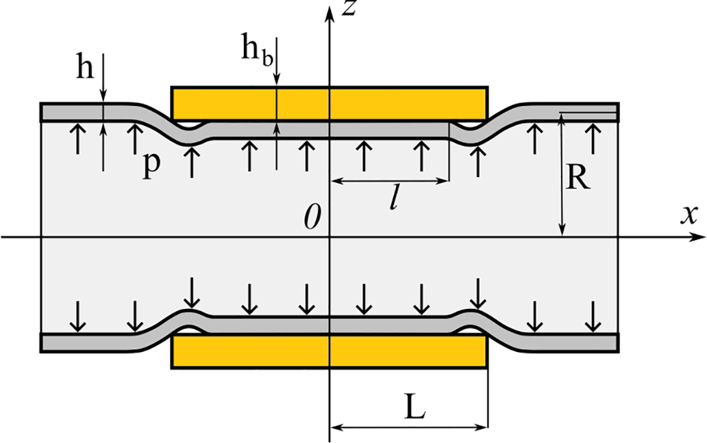
Figure 1: The calculation scheme for the repair joint.
In the case of axisymmetric deformation of cylindrical shells, the complete system of equations of the Mindlin-Reissner theory can be reduced [10] to two governing equations for the deflection W of the mid-surface and the angle of rotation γ of the normal element. The calculation scheme for the repair joint distinguishes three sections: Section I: contact between the pipeline and the bandage (0< x < l); Section II: the gap between the bandage and the pipeline (l < x < L); Section III: the pipeline without the bandage (x > L). Due to symmetry with respect to the plane x = 0, the boundary value problem is considered for half of the repair joint. For the first section, the determining equations are as follows:
At the section where there is a gap between the bandage and the pipeline, the condition of the repair joint is determined by a system of equations:
Deformation of the pipeline outside the repair joint is described by a system of equations:
In Eqs. (1)–(3), the following symbols are used: PK—contact pressure between the pipeline and the bandage, P—internal pressure in the pipeline; WI, WII, WIII—pipeline deflection in the first, second, and third sections, respectively; γI, γII, γIII—angles of rotation of the normal element of the pipeline; Wb, γb—deflection and angle of rotation of the bandage; g, gb, b, bb—parameters depending on the characteristics of the materials and dimensions of the bandage and pipeline:
The characteristic method is used to find general solutions to systems of linear differential Eqs. (1)–(3). Details on finding general solutions are provided in the Appendix A.
The general solution of the system of equations for the repair joint contains sixteen arbitrary integration constants dj. Another unknown is the length of the contact area l. To find all unknowns, the following seventeen conditions are used at the boundaries of the sections:
The system of algebraic equations obtained from the boundary conditions is nonlinear with respect to the length of the contact area l. The solutions to the system were found numerically using the Maple mathematical software package.
The calculations were performed with the following fixed parameters of the repair joint: R = 500 mm; h = 10 mm; hb = 30 or 40 mm; P = 6 MPa. The pipeline is made of steel with elastic characteristics: E = 200 GPa; v = 0.3. Orthotropic fiberglass with the following mechanical characteristics was considered as the bandage material: Ex = 18.6 GPа; Eθ = 24.6 GPа; Gxz = 3 GPа; νxθ = 0.15.
When designing repair joints, the possibility of areas where the bandage separates from the pipeline should be taken into account. The use of classical shell theory or models of absolutely rigid bandage always leads to the appearance of such areas. An analysis based on Mindlin-Reissner shell theory allows the dimensions of non-contact zones to be determined depending on the parameters of the repair joint. Fig. 2 shows the results of calculations of the length of the non-contact zone Δ = (L − l) depending on the length of the band for different band thicknesses.
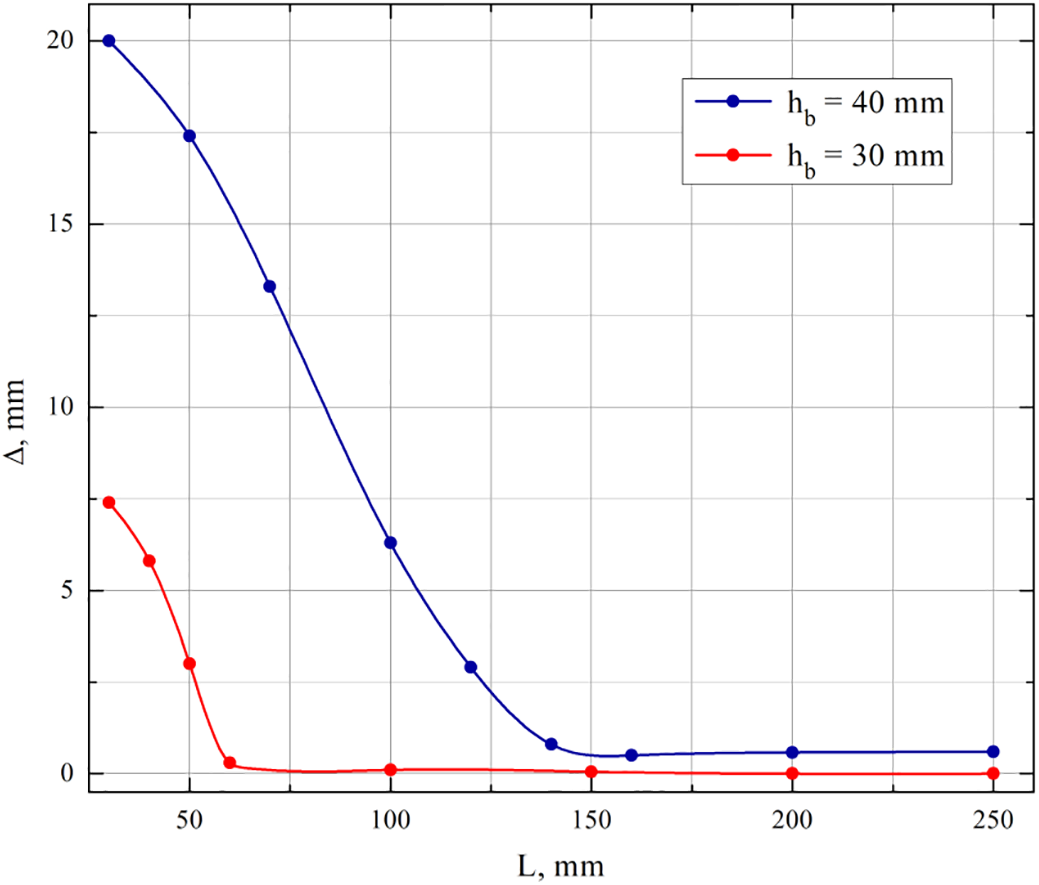
Figure 2: Dependence of the length of the non-contact zone on the length of the bandage.
The graph for a band thickness of 40 mm shows that with an unlimited increase in band length, the length of the non-contact zone asymptotically tends to a constant value. For a smaller bandage thickness, the length of the non-contact zone decreases to values smaller than the pipe thickness, and the contact area extends over almost the entire length of the band.
The equations given can be used to solve the problem of contact for the bandage glued to a pipeline. To do this, the system of Eq. (1) must be considered over the entire interval 0 < x < L, and outside the bandage, Eq. (3) must be used. Fig. 3 shows graphs of the change in contact pressure at point x = L as the bandage length increases for bandage thicknesses of 30 and 40 mm. Negative values of contact pressure correspond to the tension of the adhesive layer.
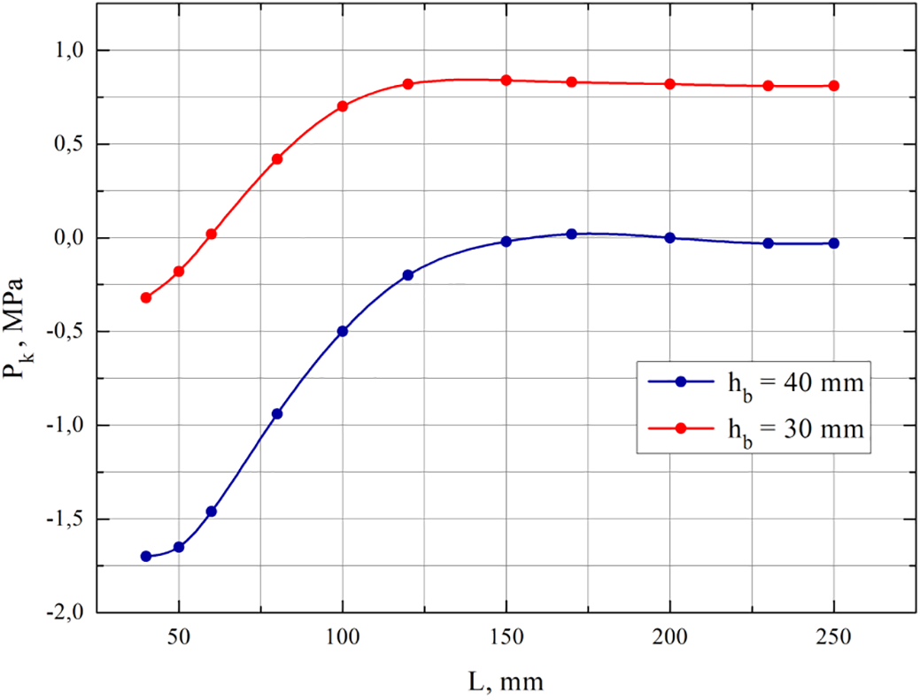
Figure 3: Dependence of contact pressure on the length of the bandage.
3 Formulation of the Elasticity Theory Problem for the Repair Joint
The analysis of the contact interaction between the pipeline and the composite bandage, performed in Section 2 based on shell theory, makes it possible to specify the basic dimensions of the bandage for non-detachable contact. A detailed analysis of the stress state in the damaged section of the pipeline reinforced with a composite bandage is performed within the framework of a spatial elasticity theory problem [29]. For the mathematical formulation of the problem, a complete system of equations of an axisymmetric problem in a cylindrical coordinate system is used. Two areas of the meridian section of the repair joint are considered: the section of the damaged pipeline section and the section of the cylindrical bandage (Fig. 4).
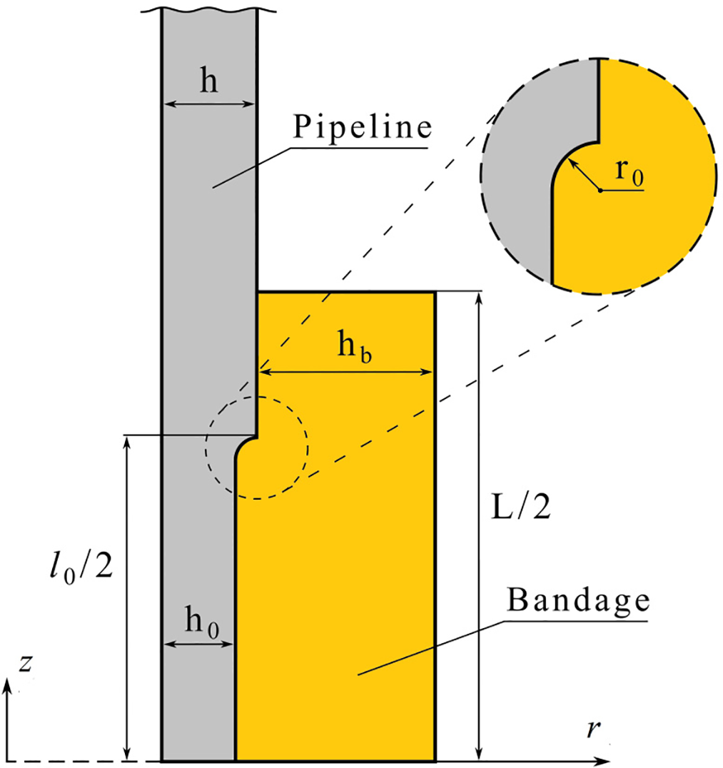
Figure 4: Meridional section of the repair join.
In the pipeline and bandage areas, the stresses satisfy the differential equilibrium equations without taking into account volumetric forces.
Displacements and strains in the pipeline and bandage areas satisfy geometric relations in cylindrical coordinates.
For the steel pipeline region, Hooke’s law for isotropic bodies is used as the physical relationship.
In the area of composite bandages, strains are related to stresses by the physical relationships of an orthotropic body.
At the boundaries between the pipeline and the bandage, the conditions of continuity of displacement and total stress are satisfied. Normal pressure P is applied to the inner surface of the pipeline. The repair joint design is symmetrical about the plane of the central cross section, so the corresponding symmetry conditions are specified for it.
For such complex boundary problems in elasticity theory, it is impossible to obtain an exact analytical solution. In this work, the finite element method was used to obtain numerical results.
4 Finite Element Analysis of the Repair Joint
The structure analysis of the stress state of the repair joint is performed using the finite element method in the ANSYS software package. Geometric modeling of the repair joint was performed in the ANSYS preprocessor according to Fig. 4. An axisymmetric section of the pipeline with corrosion damage on a segment of length l0 is considered. The initial thickness of the pipeline h in the damaged section is reduced to a thickness h0. Cylindrical bandage of length L with wall thickness hb is installed on the pipeline, filling the entire space of the damaged section of the pipeline. Due to axial symmetry, it is sufficient to consider the area of the meridian section for geometric modeling, and when creating a finite element model, use the PLANE 183 element with quadratic approximation of displacements and Option Axisymmetric. Discretization was performed using the Smart Size tool, and the finite element model consisted of 25,434 nodes and 12,391 elements. The maximum size of the finite element was 0.5 mm in areas of undamaged piping, while in the stress concentration zone, the minimum size of the finite element was 0.01 mm. This made it possible to study in detail the distribution of stresses along the radius of the fillet r0 = 2 mm.
To evaluate the quality of the finite element mesh, a comparison of nodal and element results was performed. The difference in the maximum equivalent stress values in the pipeline did not exceed 0.1%. For the bandage, the difference in maximum normal stresses was 0.6%. The repair joint design is symmetrical about the cross-sectional plane y = 0, so to save computational resources, the analysis was performed for half the length of the joint y > 0.
The repair bandage is made of T700 carbon fiber reinforced with 3234 epoxy composite with high mechanical properties. In terms of elastic properties, this material is linearly orthotropic. The complete set of elasticity characteristics of this composite is given in Table 1.
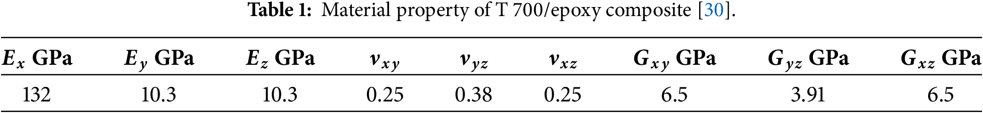
A large number of short-term strength criteria have been proposed for evaluating the strength of composite materials. The most widely used are limit state equations in the form of second-order polynomials depending on the components of the stress (or strain) tensor. Second-order criteria can be used to take into account not only differences in strength limits in different directions, but also to reflect the differences in strength limits under tension and compression. If we use Voigt notation and write the coordinate stresses as a vector
For orthotropic materials in a coordinate system coinciding with the planes of symmetry of mechanical properties, this criterion contains 12 independent constants:
The practical application of second-order criteria is limited by the need to experimentally determine a large number of material parameters contained in such criteria. A certain compromise was made in the formulation of the Tsai-Wu criterion, where the coefficients for normal stress products are not considered independent. The coefficients of the polynomial (10) are determined from the experimental values of the strength limits in nine basic experiments. The strength limits given in Table 2 were used to perform the strength analysis of the bandage.
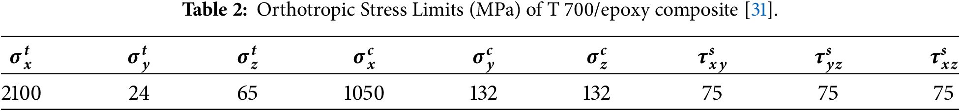
In Table 2, the superscript t corresponds to the tensile strength limit, the superscript c corresponds to the compressive strength limit, and the superscript s corresponds to the shear strength limit.
5 Results of Finite Element Analysis of the Repair Joint
Numerical results are given for a repair joint with the following geometric parameters: L = 240 mm, hb = 30 mm, l0 = 200 mm, h = 10 mm, h0 = 8 mm, internal pressure P = 6 MPa.
In the first stage of computer modeling and structural analysis, the damaged section of the pipeline was calculated. Corrosion damage is modeled by reducing the thickness of the pipeline wall by 20% of its original size. Fig. 5a,b shows the distribution of radial Ux and axial Uy displacements in the damaged section. The distribution of axial and circumferential stresses is shown in Fig. 6a,b.
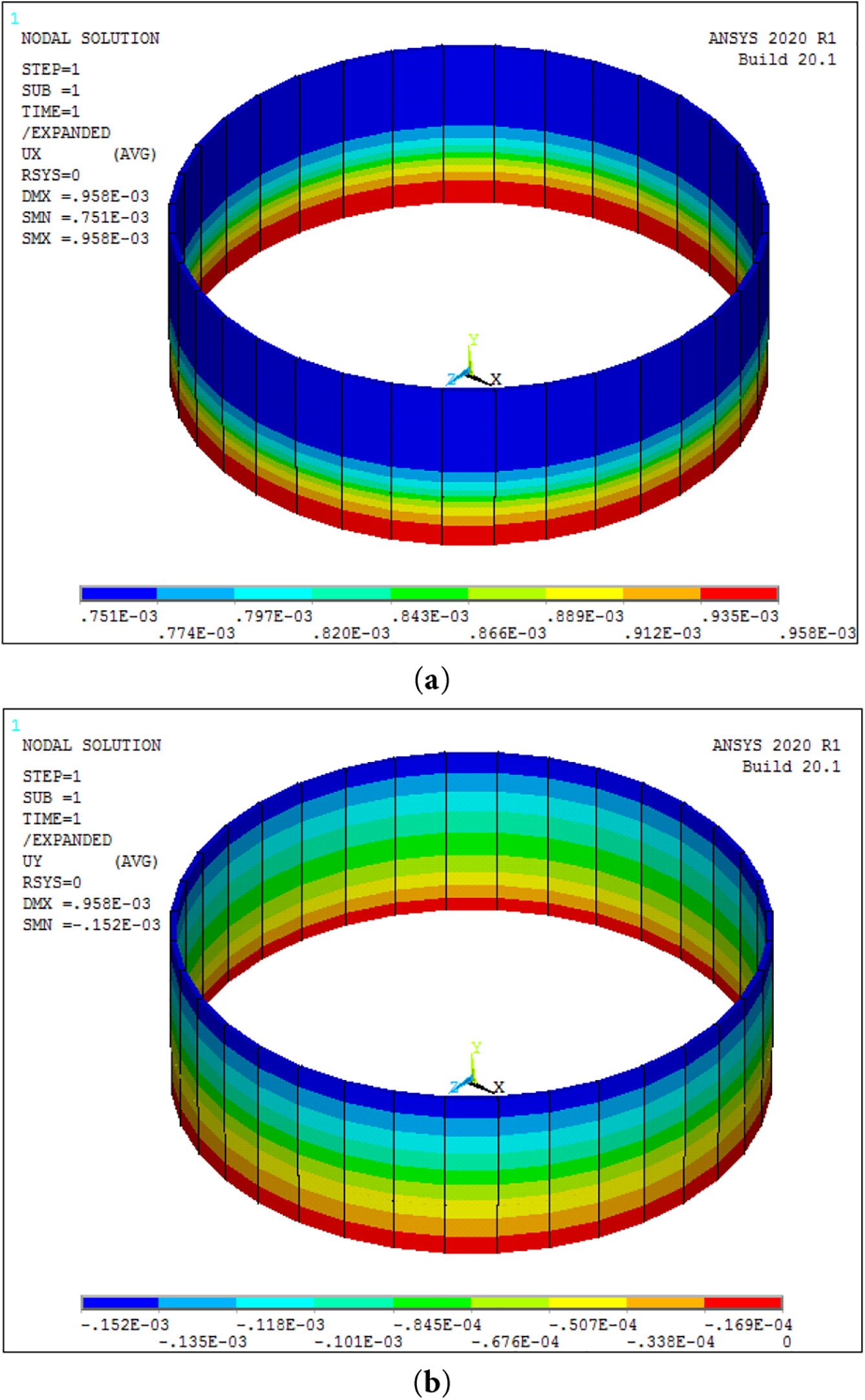
Figure 5: Distribution of radial (a) and axial (b) displacements in the damaged section of the pipeline (unit—meters).
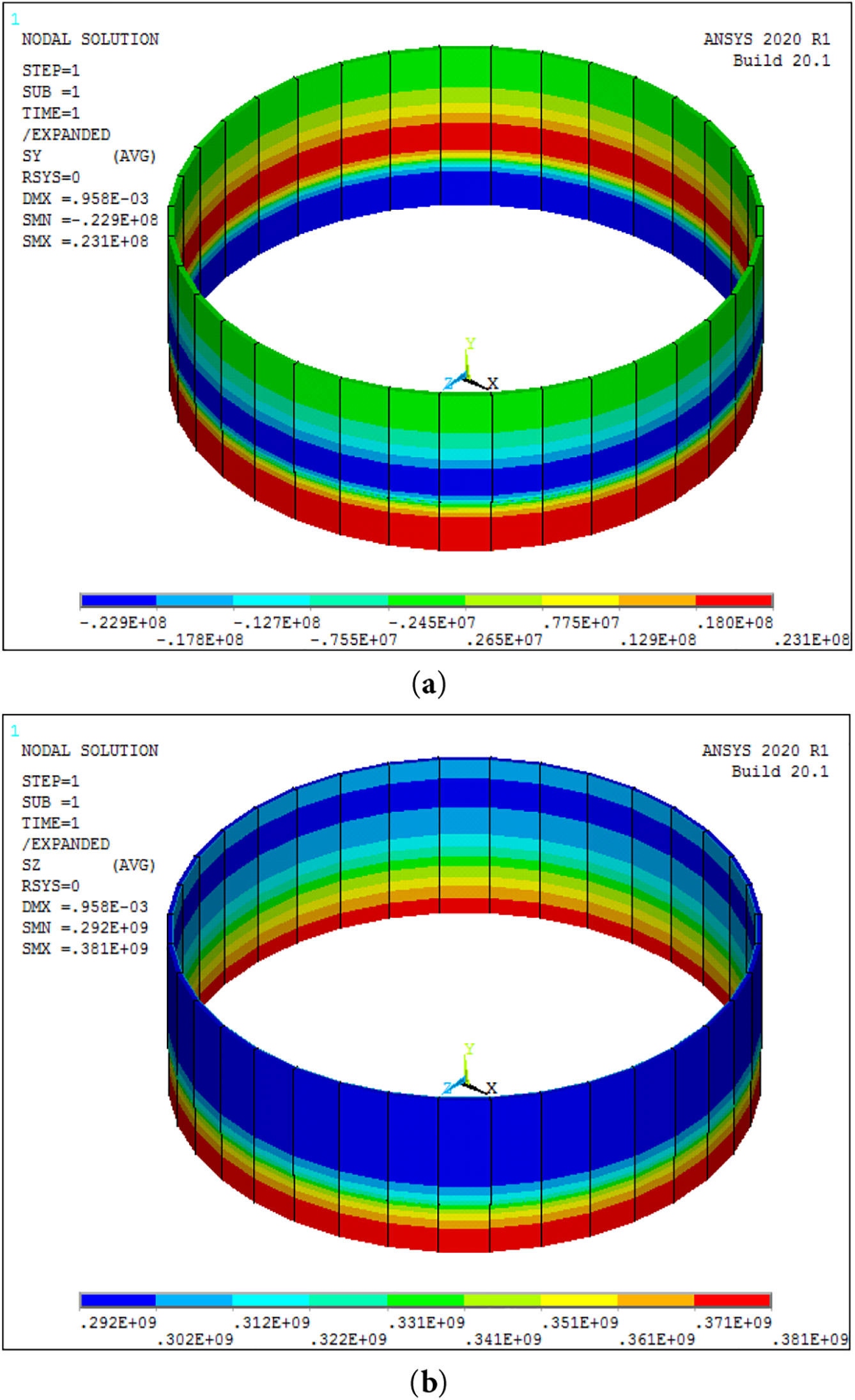
Figure 6: Distribution of axial (a) and circumferential (b) stresses in the damaged section of the pipeline (unit—Pascals).
The analysis shows that corrosion damage causes significant disturbance of the stress-free state characteristic of a cylindrical shell loaded with internal pressure. Thus, in the central part of the damaged area, the axial stresses vary in thickness from –22.9 MPa on the inner surface to +23.1 MPa on the outer surface. The circumferential stresses are also unevenly distributed across the thickness of the damaged area. In the central part of the damaged area, they vary from 371 MPa on the inner surface to 381 MPa on the outer surface. For comparison, the circumferential stresses according to the momentless theory of shells of an undamaged pipeline with the parameters considered are equal to 300 MPa.
To evaluate the effectiveness of the repair joint, a structural analysis of the damaged section of the pipeline with the composite bandage installed was performed. Internal pressure P = 6 MPa is applied after the composite bandage has been installed and fully cured. The dimensions of the bandage are as follows: length L = 0.24 m, thickness hb = 0.03 m.
Fig. 7a,b shows the distribution of radial Ux and axial Uy displacements in a repair joint in which a composite bandage has been installed on the damaged section of the pipeline. The distribution of axial and circumferential stresses is shown in Fig. 8a,b.
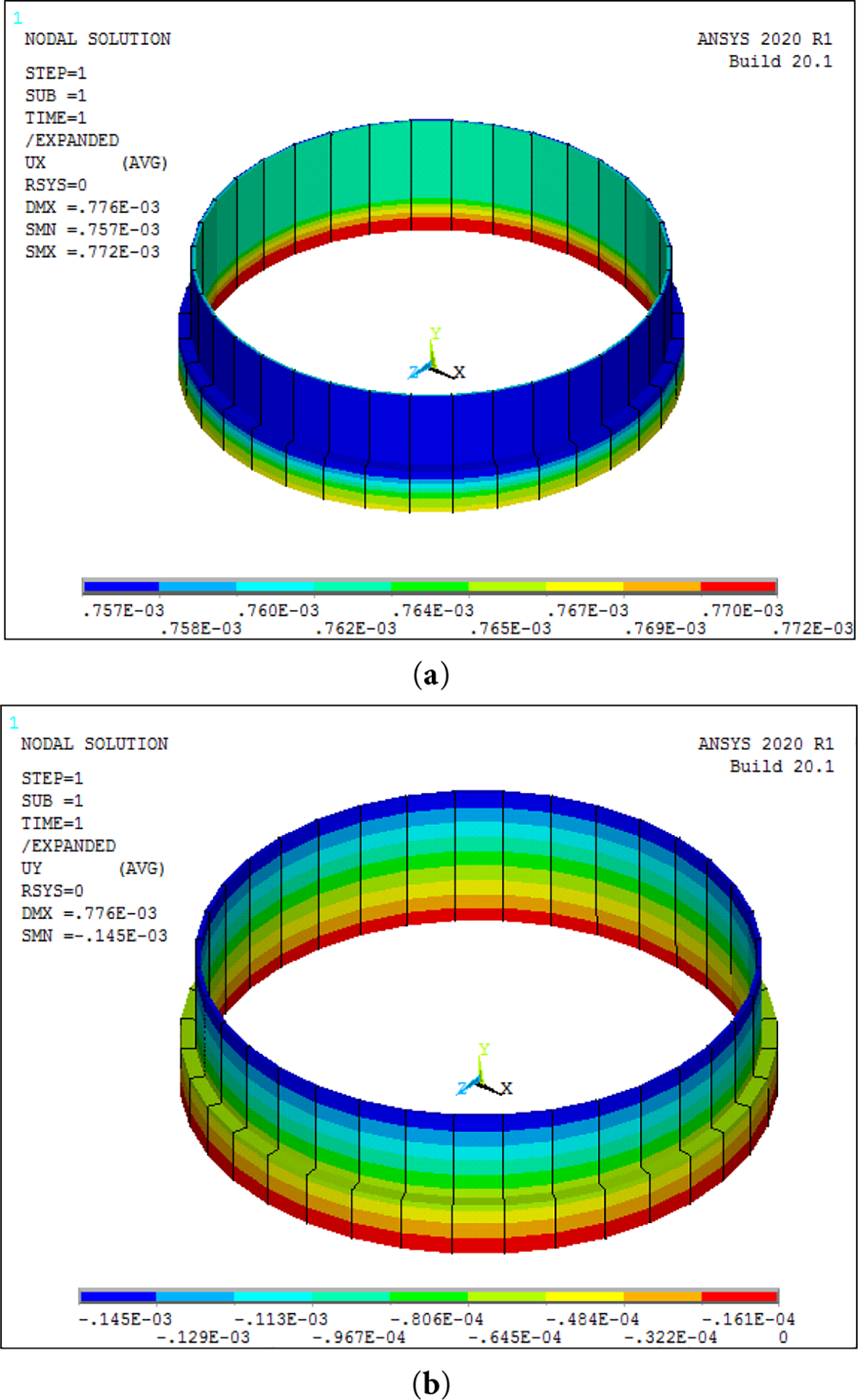
Figure 7: Distribution of radial (a) and axial (b) displacements in a repair joint (unit—meters).
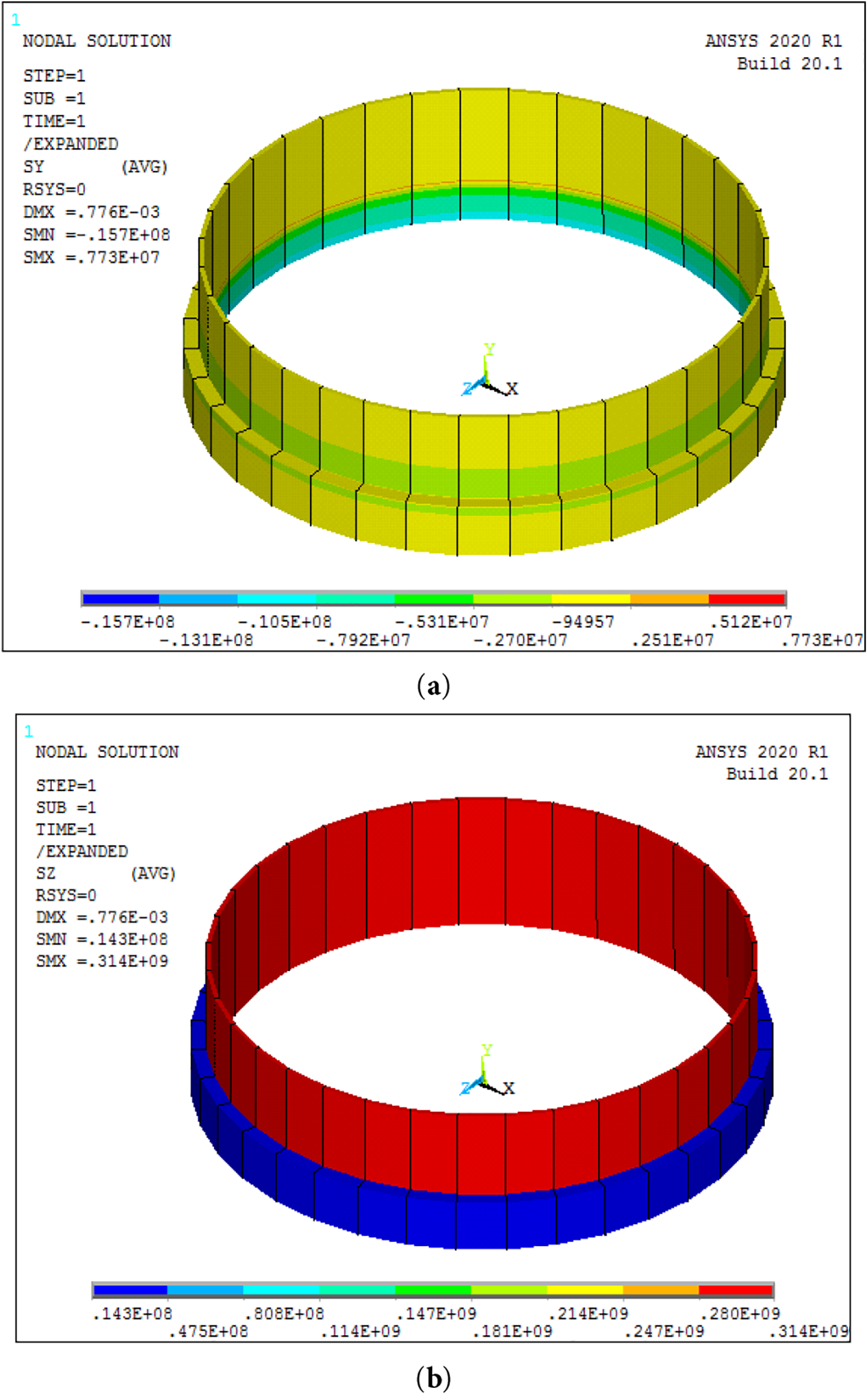
Figure 8: Distribution of axial (a) and (b) circumferential stresses in a repair joint (unit—Pascals).
The results of the structural analysis of the repair joint show that reinforcement with a composite bandage leads to a significant reduction in stresses on the damaged section of the pipeline. The bending component caused by the uneven distribution of axial stresses across the thickness of the damaged section of the pipeline practically disappears. Circumferential stresses are reduced to a level corresponding to the momentless state of an undamaged pipeline. A slight increase (less than 5%) in circumferential stresses remains in the fillet area of the damaged section.
The steel pipeline in the repair joint area is under complex stress conditions. To assess the strength of the steel section, Fig. 9 shows the distribution of the equivalent von Mises stress separately for the pipeline. The results of the strength analysis of the bandage in the ANSYS post-processor are presented in Fig. 10 in the form of a normalized Tsai-Wu Strength Index. The limit state at which the composite fails corresponds to an index value of one.
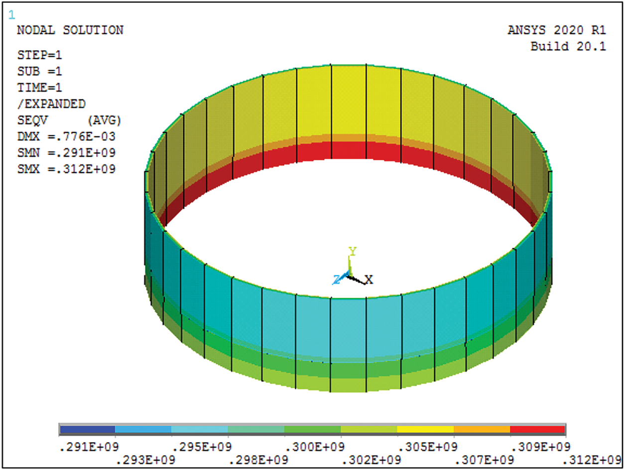
Figure 9: Distribution of equivalent stress (unit—Pascals).
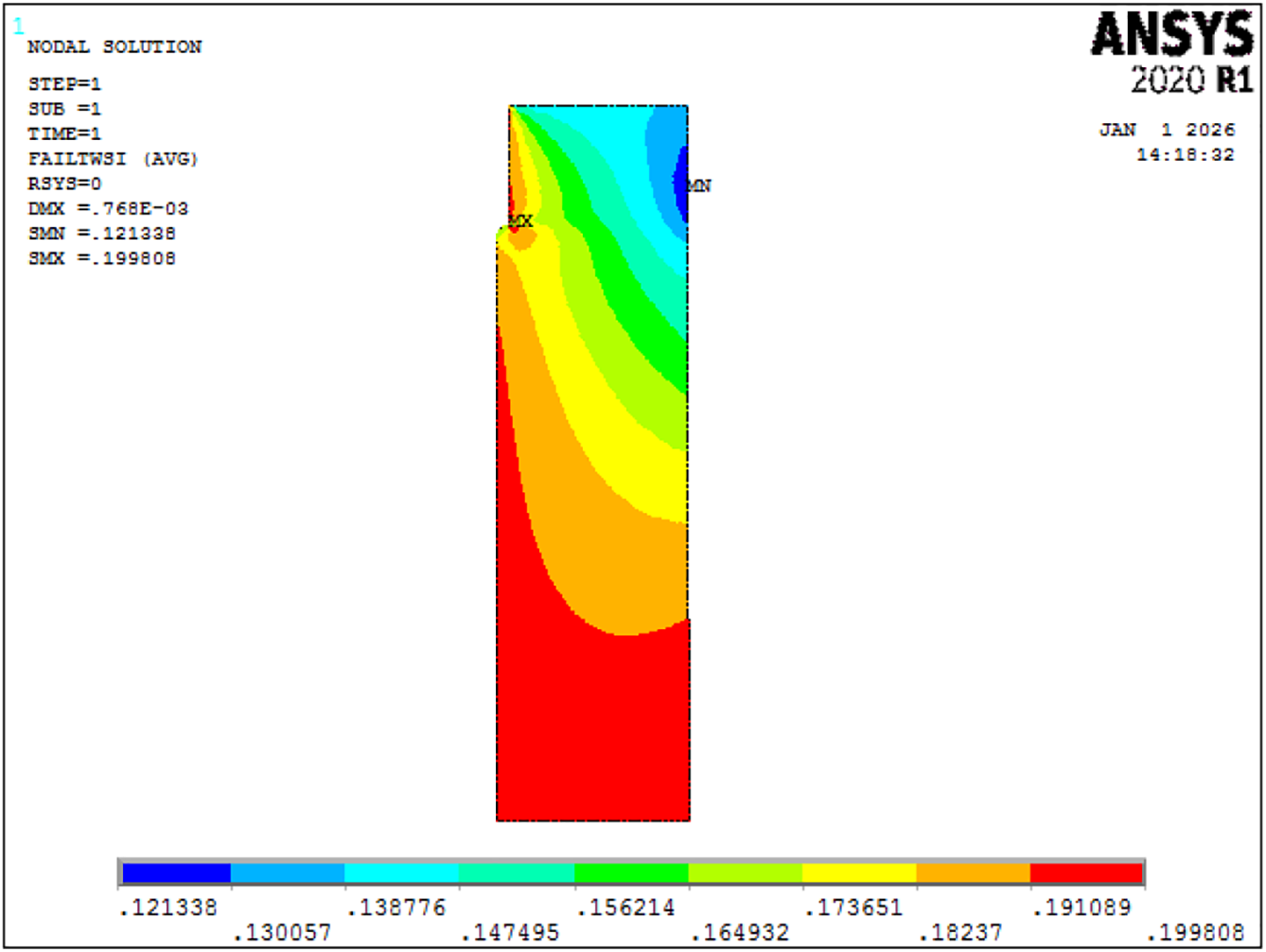
Figure 10: Distribution of Tsai-Wu Strength Index (dimensionless).
An analysis of the strength of the repair joint shows that the installation of a composite bandage eliminates dangerous stress concentrations in the damaged section of the pipeline. The equivalent stress in the steel pipeline varies within a negligible range from 291 to 312 MPa. The accepted parameters of the bandage provide sufficient margin factor for the composite part of the repair joint.
The computer modeling and structural analysis conducted in this study demonstrate the efficacy of composite bandages for reinforcing corroded steel pipelines, offering a non-invasive repair method that maintains operational continuity. Using the Mindlin-Reissner shell theory, the contact interaction between the pipeline and bandage was evaluated, revealing that non-contact zones at the bandage edges diminish with increasing bandage length and decrease significantly for thinner bandages (e.g., approaching pipe thickness for hb = 30 mm). This analysis enables the optimization of bandage dimensions to ensure full contact and prevent delamination under standard operating pressures of 6 MPa.
Finite element simulations in ANSYS further confirmed that installing a composite bandage on a pipeline section with 20% wall thickness reduction due to corrosion substantially mitigates stress concentrations. In the damaged unreinforced section, circumferential stresses ranged from 371 MPa (inner) to 381 MPa (outer), exceeding the nominal 300 MPa for an intact pipe. Post-reinforcement, these stresses were reduced to near-momentless levels (approximately 300 MPa), with axial bending components nearly eliminated. Equivalent von Mises stresses in the steel stabilized between 291 and 312 MPa, while the Tsai-Wu strength index for the composite remained well below 1, indicating a robust safety margin.
As practical recommendations, engineers at the design stage should use the results presented in Fig. 2 to select the minimum band length sufficient to ensure uninterrupted contact with the pipeline. Where necessary, the graphs in Fig. 3 allow the magnitude of tensile stresses in the adhesive layer to be estimated.
This work was performed within the following limitations. The problem was considered within the framework of linear physical models of materials in a static setting. The influence of temperature and humidity can be taken into account when specifying the elastic properties of materials. The possibility of the bandage detaching from the pipeline is taken into account in the preliminary analysis in Section 2, where the conditions for non-detachable contact are established. At the FEM analysis stage, complete adhesion of steel to the composite is assumed.
Future research could extend this to dynamic loading conditions, Finite Element Method (FEM)analysis in non-axisymmetric setting and multi-defect interactions, or long-term environmental degradation to further enhance repair durability and predictive accuracy. External loads on the pipeline were not considered in this study. The impact of the external environment on underground and underwater pipelines may be the subject of further research.
Acknowledgement: Not applicable.
Funding Statement: The authors received no specific funding.
Author Contributions: The authors confirm contribution to the paper as follows: Conceptualization, Maria Tănase and Gennadiy Lvov; methodology, Maria Tănase and Gennadiy Lvov; software, Maria Tănase; validation, Gennadiy Lvov; formal analysis, Maria Tănase and Gennadiy Lvov; investigation, Maria Tănase and Gennadiy Lvov; resources, Maria Tănase; data curation, Maria Tănase and Gennadiy Lvov; writing—original draft preparation, Maria Tănase and Gennadiy Lvov; writing—review and editing, Maria Tănase and Gennadiy Lvov; visualization, Gennadiy Lvov; supervision, Gennadiy Lvov; project administration, Maria Tănase; funding acquisition, Maria Tănase. All authors reviewed and approved the final version of the manuscript.
Availability of Data and Materials: The authors confirm that the data supporting the findings of this study are available within the article.
Ethics Approval: Not applicable.
Conflicts of Interest: The authors declare no conflicts of interest.
Appendix A:
The roots of the characteristic equation of system (2):
are complex in a wide range of characteristics of real materials. In the contact-free section, the solution of the system of Eqs. (2) for the pipeline is as follows:
where:
Similarly, general solutions are found for the deflection and angle of rotation of the normal element of the bandage:
where:
For the pipeline outside the repair section, the solution of the system of Eq. (3) does not contain terms that tend to infinity as the distance from the repair joint installation site increases.
Let us transform the equations of system (1), which describe the behavior of the structure in the contact section 0 < x < l. Excluding the contact pressure and the equality of the deflections of the tire and the pipeline, the system of equations for the first section can be written as follows:
where:
The solution of the system of Eq. (8) determines the deflection and angles of rotation of the normal in the contact zone.
References
1. ASME PCC-2-2018. Repair of pressure equipmentand piping. New York, NY, USA: ASME; 2018. [Google Scholar]
2. ISO 24817:2017. Petroleum, petrochemical and natural gas industries—composite repairs of pipework—qualification and design, installation, testing and inspection. Geneva, Switzerland: International Organization for Standardization; 2017. [Google Scholar]
3. Chen J, Wang H, Salemi M, Balaguru PN. Finite element analysis of composite repair for damaged steel pipeline. Coatings. 2021;11(3):301. doi:10.3390/coatings11030301. [Google Scholar] [CrossRef]
4. Lyapin AA, Chebakov MI, Dumitrescu A, Zecheru G. Finite-element modeling of a damaged pipeline repaired using the wrap of a composite material. Mech Compos Mater. 2015;51(3):333–40. doi:10.1007/s11029-015-9504-9. [Google Scholar] [CrossRef]
5. Dumitrescu A, Minescu M, Dinita A, Lambrescu I. Corrosion repair of pipelines using modern composite materials systems: a numerical performance evaluation. Energies. 2021;14(3):615. doi:10.3390/en14030615. [Google Scholar] [CrossRef]
6. Skaliukh AS, Chebakov MI, Dumitrescu A. Analytical modeling of the damaged zone of pipelines repaired with composite materials systems. In: Barkanov EN, Dumitrescu A, Parinov IA, editors. Non-destructive testing and repair of pipelines. Cham, Switzerland: Springer International Publishing; 2018. p. 369–86. doi:10.1007/978-3-319-56579-8_23. [Google Scholar] [CrossRef]
7. Zecheru GH, Dumitrescu A, Diniţă A, Yukhymets P. Design of composite repair systems. In: Barkanov EN, Dumitrescu A, Parinov IA, editors. Non-destructive testing and repair of pipelines. Cham, Switzerland: Springer International Publishing; 2018. p. 269–85. doi:10.1007/978-3-319-56579-8_17. [Google Scholar] [CrossRef]
8. Cherpakov AV, Chebakov MI, Zecheru G, Dumitrescu A. Modeling of corrosion in filler defect in the repair of pipes overlay composite bandage. In: Parinov IA, Chang SH, Jani MA, editors. Advanced materials. Cham, Switzerland: Springer International Publishing; 2017. p. 373–80. doi:10.1007/978-3-319-56062-5_31. [Google Scholar] [CrossRef]
9. Lvov I, Beschetnikov DA. Modeling of the contact interaction between steel pipe and composite bandage. In: Barkanov EN, Dumitrescu A, Parinov IA, editors. Non-destructive testing and repair of pipelines. Cham, Switzerland: Springer International Publishing; 2018. p. 339–51. doi:10.1007/978-3-319-56579-8_21. [Google Scholar] [CrossRef]
10. Barkanov E, Beschetnikov D, Lvov G. Effect of technological tensioning on the efficiency of reinforcement of pipelines with composite bands. Mech Compos Mater. 2015;50(6):725–32. doi:10.1007/s11029-015-9461-3. [Google Scholar] [CrossRef]
11. Chebakov MI, Nedin RD, Lyapin AA. Finite-element modeling of a repaired pipeline containing two volumetric surface defects. In: Barkanov EN, Dumitrescu A, Parinov IA, editors. Non-destructive testing and repair of pipelines. Cham, Switzerland: Springer International Publishing; 2018. p. 311–20. doi:10.1007/978-3-319-56579-8_19. [Google Scholar] [CrossRef]
12. Chebakov MI, Zecheru GH, Chebanenko VA. Assessment of interacting volumetric surface defects. In: Barkanov EN, Dumitrescu A, Parinov IA, editors. Non-destructive testing and repair of pipelines. Cham, Switzerland: Springer International Publishing; 2018. p. 153–65. doi:10.1007/978-3-319-56579-8_11. [Google Scholar] [CrossRef]
13. Dumitrescu A, Zecheru GH, Diniţă A. Characterisation of volumetric surface defects. In: Barkanov EN, Dumitrescu A, Parinov IA, editors. Non-destructive testing and repair of pipelines. Cham, Switzerland: Springer International Publishing; 2018. p. 117–35. doi:10.1007/978-3-319-56579-8_9. [Google Scholar] [CrossRef]
14. Andrade DM, Areias BS, Martins Costa ML, de Freitas Rachid FB, da Costa Mattos H. Failure of composite repair systems used in corroded pipelines due to pressure transients. Eng Fail Anal. 2025;171(9):109368. doi:10.1016/j.engfailanal.2025.109368. [Google Scholar] [CrossRef]
15. Useche J, Padilla C. Progessive fatigue failure analysis of composite wrap repairs in submerged pipelines under vortex induced vibrations. In: Proceedings of the Rio Pipeline Conference & Exhibition 2023; 2023 Aug 8–10; Rio de Janeiro, Brazil. [Google Scholar]
16. Zecheru G, Dumitrescu A, Draghici G, Yukhymets P. Reinforcement effects obtained by applying composite material sleeves to repair transmission pipelines. Mater Plast. 2016;53(2):252–8. [Google Scholar]
17. Shamsuddoha M, Manalo A, Aravinthan T, Mainul Islam M, Djukic L. Failure analysis and design of grouted fibre-composite repair system for corroded steel pipes. Eng Fail Anal. 2021;119(3):104979. doi:10.1016/j.engfailanal.2020.104979. [Google Scholar] [CrossRef]
18. Chan PH, Tshai KY, Johnson M, Choo HL, Li S, Zakaria K. Burst strength of carbon fibre reinforced polyethylene strip pipeline repair system-a numerical and experimental approach. J Compos Mater. 2015;49(6):749–56. doi:10.1177/0021998314525652. [Google Scholar] [CrossRef]
19. Niksirat M, Rahimi G, Hosseini S, Liaghat G. Experimental and numerical investigation of repaired pipeline by composite sleeve using DIC technique and FEM. J Pipeline Sci Eng. 2025:100349. doi:10.1016/j.jpse.2025.100349. [Google Scholar] [CrossRef]
20. Ansari Sadrabadi S, Dadashi A, Yuan S, Giannella V, Citarella R. Experimental-numerical investigation of a steel pipe repaired with a composite sleeve. Appl Sci. 2022;12(15):7536. doi:10.3390/app12157536. [Google Scholar] [CrossRef]
21. Abtahi SMR, Sadrabadi SA, Rahimi GH, Singh G, Abyar H, Amato D, et al. Experimental and finite element analysis of corroded high-pressure pipeline repaired by laminated composite. Comput Model Eng Sci. 2024;140(2):1783–806. doi:10.32604/cmes.2024.047575. [Google Scholar] [CrossRef]
22. Theisen SA, Keller MW. Comparison of patch and fully encircled bonded composite repair. In: Mechanics of composite and multi-functional materials. 1st ed. New York, NY, USA: River Publishers; 2025. Vol. 7. p. 101–6 doi:10.1007/978-3-319-41766-0_11. [Google Scholar] [CrossRef]
23. Ayaz Y, Çitil Ş, Şahan MF. Repair of small damages in steel pipes with composite patches. Materialwissenschaft Werkst. 2016;47(5–6):503–11. (In Germany). doi:10.1002/mawe.201600526. [Google Scholar] [CrossRef]
24. da Costa Mattos HS, Reis JML, Paim LM, da Silva ML, Amorim FC, Perrut VA. Analysis of a glass fibre reinforced polyurethane composite repair system for corroded pipelines at elevated temperatures. Compos Struct. 2014;114:117–23. doi:10.1016/j.compstruct.2014.04.015. [Google Scholar] [CrossRef]
25. Savari A, Rashed G, Eskandari H. Failure pressure analysis of pipe repaired by composite sleeve subjected to thermal and mechanical loadings. SN Appl Sci. 2022;4(7):200. doi:10.1007/s42452-022-05079-9. [Google Scholar] [CrossRef]
26. Zhangabay N, Ibraimova U, Bonopera M, Suleimenov U, Avramov K, Chernobryvko M, et al. Novel methodologies for preventing crack propagation in steel gas pipelines considering the temperature effect. Struct Durab Health Monit. 2025;19(1):1–23. doi:10.32604/sdhm.2024.053391. [Google Scholar] [CrossRef]
27. Zhangabay N, Suleimenov U, Bonopera M, Ibraimova U, Yeshimbetov S. A method for preventing crack propagation in a steel gas conduit reinforced with composite overlays. Struct Durab Health Monit. 2025;19(4):773–87. doi:10.32604/sdhm.2025.064980. [Google Scholar] [CrossRef]
28. Altenbach H, Beschetnikov DA, Lvov GI, Naumenko K, Sukiasov VG. Kontaktwechselwirkung einer Rohrleitung mit der Reparaturbandage aus einem Kompositwerkstoff. Forsch Im Ingenieurwesen. 2014;78(1):59–67. (In Germany). doi:10.1007/s10010-014-0173-y. [Google Scholar] [CrossRef]
29. Barber JR. Elasticity. Berlin/Heidelberg, Germany: Springer; 2023. 642 p. [Google Scholar]
30. Wang B, Xiong J, Wang X, Ma L, Zhang GQ, Wu LZ, et al. Energy absorption efficiency of carbon fiber reinforced polymer laminates under high velocity impact. Mater Des. 2013;50:140–8. doi:10.1016/j.matdes.2013.01.046. [Google Scholar] [CrossRef]
31. Hassan S, Santulli C, Yahya M, Gang C, Abu B. The potential of biomimetics design in the development of impact resistant material. FME Trans. 2018;46(1):108–16. doi:10.5937/fmet1801108h. [Google Scholar] [CrossRef]
Cite This Article
 Copyright © 2026 The Author(s). Published by Tech Science Press.
This work is licensed under a Creative Commons Attribution 4.0 International License , which permits unrestricted use, distribution, and reproduction in any medium, provided the original work is properly cited.
 Downloads
 Citation Tools