
 Submit a Paper
 Propose a Special lssue
 Open Access
ARTICLE
Optimization Study on Regenerative Organic Rankine Cycle (ORC) with Heat Source of Low-Grade Steam
1 Research Center, CNOOC Energy Conservation & Environmental Protection Service Co., Ltd., Tianjin, 300457, China
2 School of Energy and Environmental Engineering, Hebei University of Technology, Tianjin, 300401, China
* Corresponding Author: Xiang Gou. Email:
Energy Engineering 2022, 119(6), 2569-2584. https://doi.org/10.32604/ee.2022.020644
Received 04 December 2021; Accepted 25 February 2022; Issue published 14 September 2022
 View Full Text
 Download PDF
Abstract
Aiming at improving the performance of Organic Rankine Cycle (ORC) system with low-grade steam as heat source, this work studied and optimized the main operating parameters of the ORC system. The effects of evaporation temperature, superheat degree, condensation temperature and regenerator pinch temperature difference on the system performance were obtained. The optimization for the operating parameters is based on the indicators of specific net power output, waste heat pollution, cycle exergy efficiency, and total UA value (the product of overall heat transfer coefficient and heat transfer area of heat exchanger). The results show that the increase of the evaporation temperature and the superheat degree, and the decrease of the condensation temperature and regenerator pinch temperature difference can improve general system performance but lead to weaker economic performance. The optimal evaporation temperature, superheat degree, condensation temperature and regenerator pinch temperature difference are determined as 139°C, 4°C, 36°C and 8°C, respectively, reaching net power output of 114.73 kW, exergy efficiency of 37.10%. Besides, it is indicated that the regenerative ORC system can reach 13.6% additional net power output compared to the ORC system without the regenerator.Keywords
Global electricity demand heading for its fastest growth boosts global energy consumption and carbon emissions. Since renewable energy sources are economically attractive and technically mature to meet enormous energy demand [1], recovering waste heat from industrial process is an efficient approach at current stage to alleviate energy shortage and reduce carbon footprint.
Low-grade waste heat accounts for 50% or more of the heat generated by industry [2]. The Organic Rankine Cycle (ORC) technology can recover waste heat and generate electricity with low-grade heat sources. A wide range of researches are carried out about ORC technologies, covering working fluids [3], operating parameters [4,5], system configurations [6,7] and device design [8,9]. Barse et al. [10] developed an ORC model using HYSYS simulator, by studying 12 kinds if organic working fluids. They found that there was a strong correlation between the critical temperature of the working fluid and the system efficiency, and thermal efficiency could be improved by 25% with R600. The first law and the second law were applied to analyze the 20 kWe ORC system using R245fa with different low-grade heat sources, including hot water, saturated steam, and combined hot water and saturated steam [11]. The results indicated that the first law efficiency increased with the heat source temperature, and the first and the second law efficiencies decreased with the increase of pinch value. In addition, the combined hot water and saturated steam was found to be the most suitable heat source due to the lowest exergy destruction in the evaporator and the highest second law efficiency.
The operational parameters of the ORC system affect the thermal, economic performance or environmental performances of the system. Vélez et al. [12] analyzed the effects of the temperature and pressure at turbine inlet on system efficiency, and concluded that the efficiency of ORC system was positively correlated with turbine inlet temperature with constant turbine inlet pressure for the working fluids of R718, R290 and R152a, while it was negatively correlated for R600 and R600a. Multi-objective optimization of ORC system applying R245fa was investigated covering aspects of both thermodynamics and economy [13]. The effects of operating parameters of hot and cold sources, and working pump rotational speed on the off-design performances of the ORC system were analyzed. In the research, it is indicated that the raising mass flow rate and decreasing temperature of cooling water are conducive to ORC system performance, besides, the heat source temperature shows more significant influence on system performance than the cooling source temperature. Braimakis et al. [14] developed several regenerative ORC systems and optimized them for different working fluids. The maximum efficiencies in recuperative ORC systems are 3%∼5% higher than that of the non-recuperative systems. Köse et al. [15] evaluated the performance improvement of the combined ORC system with Steam Rankine Cycle (SRC) system for a varying turbine inlet pressure and temperature, with the exhausted flue gas from a 6.2 MWe gas turbine as the heat source. The maximum overall thermal efficiency and exergy efficiency of the combined cycle were 47.65% and 67.35%, respectively, with 40 bar and 225°C turbine inlet flue gas in the ORC system and 100 bar and 480°C in the SRC system.
The present work focuses on the analysis and optimization of the main operating parameters of the regenerative ORC system that recoveries heat from low-grade steam. Aspen Plus is employed to conduct the study and R245fa is selected as the organic working fluid. With the constant heat source, the performance improvement is investigated and evaluated from technical, economic and environmental aspects with varying operating parameters, including evaporation temperature, superheat degree, condensation temperature and regenerator pinch temperature difference. The multi-objective optimization aiming at comprehensive performance evaluation is applied to determine the thermodynamic parameters of ORC system.
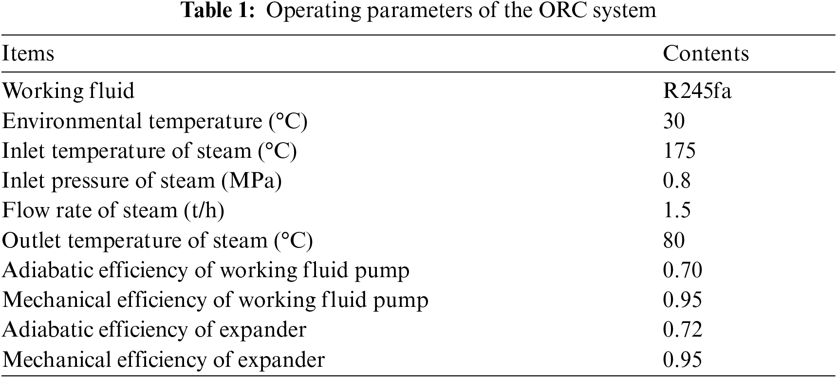
The regenerative ORC system mainly includes working fluid pump, evaporator, expander, condenser and regenerator, as shown in Fig. 1, and it can convert the absorbed heat from heat source (175°C saturated steam) into electricity and improve energy grade. According to physical properties [16], R245fa is selected as working fluid in the present ORC system with comprehensive consideration of the thermodynamic requirements and environmental impacts. The organic working fluid from the condenser at low temperature and pressure is pressurized to meet the required evaporation pressure and pumped into the regenerator to absorb heat through heat exchange, and then it absorbs heat from the heat source through the evaporator and evaporates to form high-temperature and high-pressure vapor. The working medium vapor expands in the expander to drive generator to generate electricity, and during this process the pressure and temperature of the working fluid decrease. Then, the working fluid flows through the regenerator followed by the condenser to release heat and it becomes supercooled fluid before the pump. For the regenerative ORC system, the regenerator achieves the heat transfer from the expander outlet fluid to the pump outlet fluid.

Figure 1: Regenerative ORC system
The thermodynamic process for the regenerative ORC can be depicted as 3-4-4’-1-2-2’-3 in Fig. 2.

Figure 2: T-s diagram of the ORC system
The general energy balance equations are applied to the exergy-based analysis of the ORC component as well as overall ORC [17,18]. The specific exergy can be defined as:
where h and s are the specific enthalpy, kJ/kg, and specific entropy, kJ/kg⋅K, respectively; the subscript amb represents the fluid at ambient temperature;
For the evaporator, the heat exchange amount
where
Expander's output power
where
In terms of the regenerator, the exergy loss is calculated by formula (6):
where
The heat duty
where
For the pump, the power
where
Thermodynamic analysis can be performed based on the first and the second law of thermodynamics. The cycle thermal efficiency
where
The evaluation indicators based on the second law of thermodynamics include cycle exergy efficiency, total exergy cycle loss and exergy recovery efficiency, which are defined by formulas (12)–(14), respectively:
where
Exergy recovery efficiency
where
Besides, UA value is the product of overall heat transfer coefficient and heat transfer area of heat exchanger. For the given heat exchanger, the overall heat transfer coefficient is determined, and the UA value rises with the increase of heat transfer area.
where
2.3 Multi-Objective Optimization Method
The overall evaluation indicators
The objective functions can be arranged to
The linear weighted evaluation function is obtained by formula (20):
where φ and ψ are determined by the α method [19], which can be expressed as:
where
2.4 Simulation Diagram and Parameter Studying
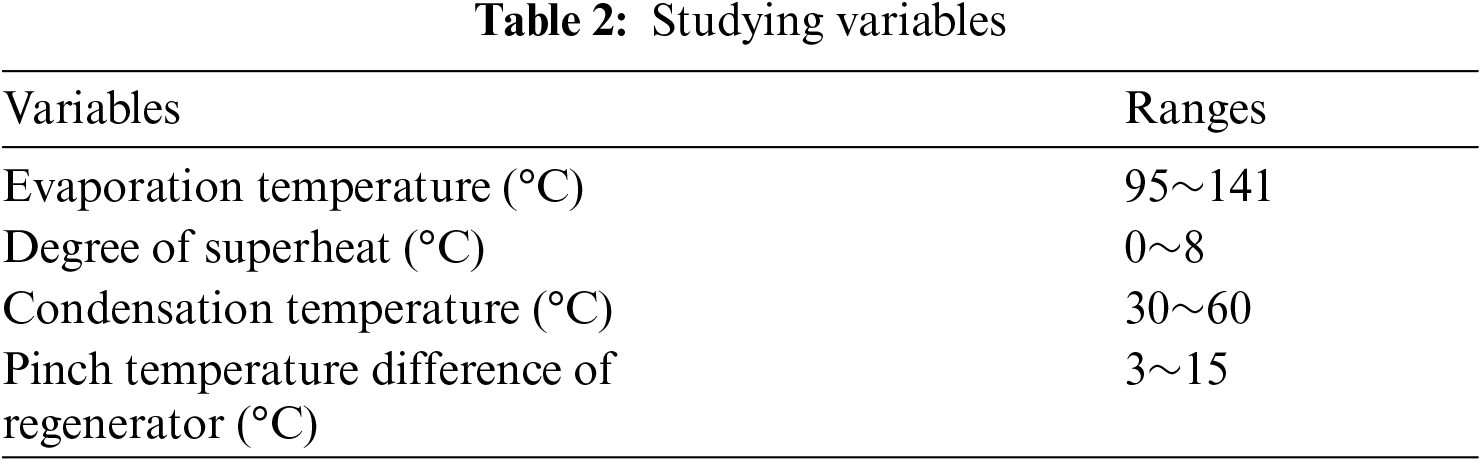
The simulation logic for optimizing the system performances and determining the crucial operating parameters are illustrated in Fig. 3. The operating parameters for simulation setup and the variables are shown in Tables 1 and 2, respectively.

Figure 3: ORC simulation logic diagram
3.1 Effect of Operating Parameters
In Fig. 4a, with the evaporation temperature increase from 95°C to 141°C, the power consumption of the condenser almost remains steady, the power consumption of pump increases, and the power generation of the expander rises from 99.88 to 146.91 kW. With the increase of evaporation temperature, the mass flow of ORC system decreases slightly and the power consumption of pump increases slightly, while the specific enthalpy difference of working fluid at the inlet and outlet of the expander increases significantly, so the net power output rises from 76.59 to 115.62 kW, with 51% increase.

Figure 4: Effect of evaporation temperature
With the constant heat input from steam and constant condensation temperature, the higher evaporation temperature contributes to the less flowrate of R245fa, thus less waste heat emission and higher system thermal efficiency, as shown in Fig. 4b. With the increase of evaporation temperature, the thermal efficiency increases from 7.53% to 11.36%, and the exergy efficiency increases from 24.76% to 37.38%. The increase of evaporation temperature and the decrease of the working fluid flow rate lead to the improvement of energy quality per unit mass, which facilitates the increase of the exergy efficiency and exergy recovery efficiency of the system.
The increase of evaporation temperature has little effect on the exergy losses of equipment except the evaporator and expander, as depicted in Fig. 4c. With the increase of evaporation temperature, the exergy loss of evaporator drops from 149.05 to 88.39 kW, but the exergy loss of expander rises from 42.99 to 62.05 kW. The total exergy loss shows a downward trend from 232.70 to 193.67 kW, with a decrease of 17%. The exergy loss of evaporator accounts for 45%∼64% of the total. The increase in evaporation temperature reduces the irreversible loss of heat transfer due to the reduced temperature difference, leading to the reduction of exergy loss in evaporator. However, the increase of average temperature difference between working fluid in expander and ambient results in the rise of exergy loss in expander.
Irrespective to the structure of heat exchanger, the UA value represents the heat transfer area as well as the cost of heat exchanger. As a result of decreased temperature difference, the heat transfer area of the evaporator enlarges. While the heat transfer area of condenser shows a small decrease owing to the slightly declined heat duty of the condenser. With the increase of evaporation temperature from 95°C to 141°C, the total UA value reaches 15% growth, from 110.30 to 126.33 kW/K, as shown in Fig. 4d.
The superheat degree is set to avoid the droplets entrainment entering the expander and the gas-liquid phase region during the expansion process. The superheat degree has rarely effect on the power consumption of condenser and pump. With the superheat degree from 0°C to 8°C, the net power output is increased from 109.50 to 119.00 kW, which is increased by 6.5%, as depicted in Fig. 5a.

Figure 5: Effect of superheat degree
In Fig. 5b, with the superheat degree increase from 0°C to 8°C, the waste heat loss is decreased by 1% since the flowrate of working fluid is reduced. Besides, the enhance of superheat degree improves the efficiency of the ORC system, the thermal efficiency, exergy efficiency and exergy recovery efficiency are all enhanced by about 9%.
The effect of superheat degree on exergy loss is reflected as Fig. 5c. The exergy losses of the pump and condenser are kept constant, and the exergy loss of the expander shows a bit of rise. The exergy loss of evaporator drops nearly 14%, and the total exergy loss declines from 199.79 to 190.29 kW.
The UA values of the evaporator and regenerator are enhanced by 38% and 53%, respectively, while that of the condenser is marginally declined, which is due to the reduced heat duty. The total UA value rises by 12%, as shown in Fig. 5d. It is reflected that the influences of unit superheat degree on the system are greater than those of evaporation temperature.
3.1.3 Condensation Temperature
When the heat source parameters are constant, the backpressure of the expander will increase with the increasing condensation temperature, resulting in the incomplete expansion of the working fluid compared to the lower condensation temperature. Therefore, the rise of condensation temperature shrinks the power generation of expander, showing 40 kW drop with 30°C condensation temperature rise, as depicted in Fig. 6a. The power consumptions of the pump and condenser indicate slightly upward trend with the increase of condensation temperature, due to the rise of working fluid flowrate. With the condensation temperature increasing from 30°C to 60°C, the net output power is reduced from 123.26 to 80.95 kW, reflecting a reduction of around 1.4 kW with per condensation temperature decrease.

Figure 6: Effect of condensation temperature
When the condensation temperature rises, the temperature of working fluid back to the evaporator rises, so more working fluid is required to absorb for the constant heat duty in the evaporator, and the resultant effect is that the heat exchange of the condenser is increased. In Fig. 6b, with 30°C enhancement of condensation temperature, the waste heat emission increases by 5%. More waste heat loss implies less heat recovered and utilized from heat source. Besides, the thermal efficiency, exergy efficiency and exergy recovery efficiency are all declined by roughly 34%.
In Fig. 6c, with the condensation temperature varying from 30°C to 60°C, the exergy losses of pump and regenerator remain constant, and those of the evaporator and expander are reduced by 20% and 30%, respectively, by contrast, that of the condenser increases by nearly five times. The total exergy loss is mainly dominated by the condenser, showing an increase of about 23%.
The UA value of the evaporator increases by 82%, since the increased condensation temperature reduces the average temperature difference of the heat transfer in the evaporator, as shown in Fig. 6d. It is remarkable that the UA value of the condenser shows steep drop in the range of the condensation temperature less than 40°C. The reduced heat duty of the condenser influences the total UA value of the system, which decreases from 221.61 to 94.65 kW/K, with about 57% decline.
3.1.4 Pinch Temperature Difference of the Regenerator
In Figs. 7a and 7b, with the increase of the regenerator pinch temperature difference, the temperature of working fluid at the evaporator inlet decreases and the flowrate of R245fa reduces. For the expander and pump, the evaporation temperature and condensation temperature are constant, so the specific power is invariant. With 12°C enhancement of the pinch temperature difference, the power generation of the expander and the power consumption of the pump are both declined by 5%, arising from the reduced working fluid, and the net input power drops about 5%. In addition, there is slight increase of the waste heat emission, and about 6% decline of the thermal efficiency, exergy efficiency and exergy recovery efficiency.

Figure 7: Effect of pinch temperature difference of the regenerator
As shown in Fig. 7c, the exergy losses of the pump and expander show slightly decline owing to the declined working fluid, while the exergy losses of evaporator, condenser and regenerator display slight increase. It is observed that 12°C addition of the pinch temperature difference of regenerator leads to about 4% increase of the total exergy loss of system.
The UA values of the evaporator, regenerator, condenser and the system all perform downward trend in Fig. 7d. With the pinch temperature difference enlarging from 3°C to 15°C, the decreases of the UA values are roughly 37% and 80% for the condenser and regenerator, respectively, besides, the total UA value decreases by 37%, from 161.29 to 100.53 kW/K.
3.2 Optimization for System Performance
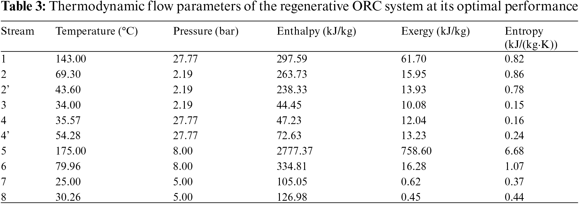
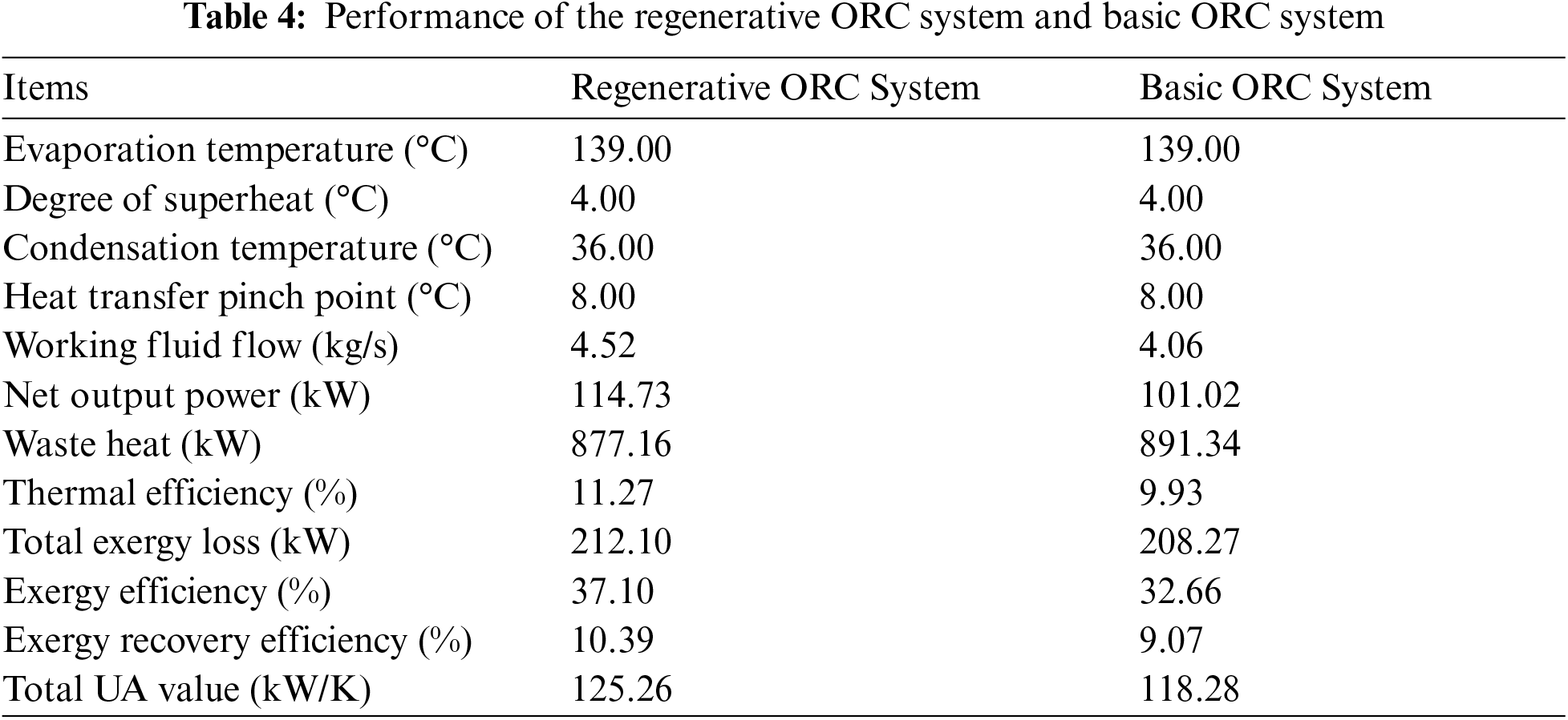
The comprehensive performance evaluation based on multi-objective optimization facilitates to determine the operating parameters of the ORC system. Corresponding to the peaks of the evaluation index F(X) in Fig. 8, the optimal evaporation temperature, superheat degree, condensation temperature and pinch temperature difference are determined as 139°C (saturation pressure of 2.78 MPa), 4°C, 36°C (saturation pressure of 0.22 MPa) and 8°C, respectively. Moreover, the thermodynamic flow parameters of the regenerative ORC system at its optimal performance are given in Table 3, and the optimized performance of the regenerative ORC system are presented and compared with the basic ORC system without a regenerator in Table 4. The required amount of working fluid and total UA value of the basic ORC system are less than those of the regenerative ORC system, while the regenerative ORC system performs the better performance in thermodynamics. The 13.6% additional net power output can be obtained by the regenerative ORC system with the constant heat input.

Figure 8: Evaluation index F(X) with different variables
The performance of the regenerative ORC system was optimized with evaporation temperature, superheat degree, condensation temperature and regenerator pinch temperature difference. The following conclusions are drawn:
The increases of the evaporation temperature and the superheat degree indicate positive influences on the net power generation, thermal efficiency, exergy efficiency and exergy recovery efficiency. The rising evaporation temperature and the superheat degree reduce the waste heat emission and the total exergy loss, but increase the total UA of the ORC system. The influences of unit superheat degree on the system are greater than those of unit evaporation temperature.
With the increase of the condensation temperature and the regenerator pinch temperature difference, the net power generation, thermal efficiency, exergy efficiency, exergy recovery efficiency and total UA value of the system are reduced, while the waste heat emission and the total exergy loss are increased. In comparison, the pinch temperature difference shows greater influence on the total UA value, while the condensation temperature indicates more powerful effect on the other indicators.
The regenerative ORC system achieves the optimal comprehensive performance with evaporation temperature of 139°C, superheat degree of 4°C, condensation temperature of 36°C and regenerator pinch temperature difference of 8°C. In addition, with the constant heat input, the 13.6% additional net power output can be obtained by the regenerative ORC system compared to the ORC system without the regenerator.
Funding Statement: This work is supported by the Science and Technology Project of CNOOC Energy Technology & Services Limited (No. HFKJ-AQ201809).
Conflicts of Interest: The authors declare that they have no conflicts of interest to report regarding the present study.
References
1. Al-Hamed, K. H. M., Dincer, I. (2021). A comparative review of potential ammonia-based carbon capture systems. Journal of Environmental Management, 287, 112357. DOI 10.1016/j.jenvman.2021.112357. [Google Scholar] [CrossRef]
2. Safarian, S., Aramoun, F. (2015). Energy and exergy assessments of modified Organic Rankine Cycles (ORCs). Energy Reports, 1, 1–7. DOI 10.1016/j.egyr.2014.10.003. [Google Scholar] [CrossRef]
3. Fan, W., Han, Z., Li, P., Jia, Y. (2020). Analysis of the thermodynamic performance of the organic Rankine Cycle (ORC) based on the characteristic parameters of the working fluid and criterion for working fluid selection. Energy Conversion and Management, 211, 112746. DOI 10.1016/j.enconman.2020.112746. [Google Scholar] [CrossRef]
4. Sun, X., Liu, L., Dong, Y., Zhuang, Y., Li, J. et al. (2021). Multi-objective optimization and thermo-economic analysis of an enhanced compression-absorption cascade refrigeration system and ORC integrated system for cooling and power cogeneration. Energy Conversion and Management, 236, 114068. DOI 10.1016/j.enconman.2021.114068. [Google Scholar] [CrossRef]
5. Wang, X., Liu, X., Zhang, C. (2014). Parametric optimization and range analysis of Organic Rankine Cycle for binary-cycle geothermal plant. Energy Conversion and Management, 80, 256–265. DOI 10.1016/j.enconman.2014.01.026. [Google Scholar] [CrossRef]
6. Nondy, J., Gogoi, T. K. (2021). Exergoeconomic investigation and multi-objective optimization of different ORC configurations for waste heat recovery: A comparative study. Energy Conversion and Management, 245, 114593. DOI 10.1016/j.enconman.2021.114593. [Google Scholar] [CrossRef]
7. Xiao, X., Zhao, W., Wang, W., Zhang, W., Bu, X. et al. (2021). Analysis of solar direct-driven organic Rankine cycle powered vapor compression cooling system combined with electric motor for office building Air-conditioning. Energy Engineering, 118(1), 89–101. DOI 10.32604/EE.2020.014016. [Google Scholar] [CrossRef]
8. Jankowski, M., Klonowicz, P., Borsukiewicz, A. (2021). Multi-objective optimization of an ORC power plant using one-dimensional design of a radial-inflow turbine with backswept rotor blades. Energy, 237, 121506. DOI 10.1016/j.energy.2021.121506. [Google Scholar] [CrossRef]
9. Li, L., Tao, L., Gou, Y., Zhang, S. (2020). Improvement and experimental study of scroll expander for organic Rankine cycle. Energy Engineering, 117(4), 225–235. DOI 10.32604/EE.2020.010892. [Google Scholar] [CrossRef]
10. Barse, K. A., Mann, M. D. (2016). Maximizing ORC performance with optimal match of working fluid with system design. Applied Thermal Engineering, 100, 11–19. DOI 10.1016/j.applthermaleng.2016.01.167. [Google Scholar] [CrossRef]
11. Kong, R., Deethayat, T., Asanakham, A., Vorayos, N., Kiatsiriroat, T. (2019). Thermodynamic performance analysis of a R245fa organic Rankine cycle (ORC) with different kinds of heat sources at evaporator. Case Studies in Thermal Engineering, 13, 100385. DOI 10.1016/j.csite.2018.100385. [Google Scholar] [CrossRef]
12. Vélez, F., Segovia, J. J., Martín, M. C., Antolín, G., Chejne, F. et al. (2012). Comparative study of working fluids for a rankine cycle operating at low temperature. Fuel Processing Technology, 103, 71–77. DOI 10.1016/j.fuproc.2011.09.017. [Google Scholar] [CrossRef]
13. Wang, L., Bu, X., Li, H. (2020). Multi-objective optimization and off-design evaluation of organic rankine cycle (ORC) for low-grade waste heat recovery. Energy, 203, 117809. DOI 10.1016/j.energy.2020.117809. [Google Scholar] [CrossRef]
14. Braimakis, K., Karellas, S. (2018). Energetic optimization of regenerative Organic Rankine Cycle (ORC) configurations. Energy Conversion and Management, 159, 353–370. DOI 10.1016/j.enconman.2017.12.093. [Google Scholar] [CrossRef]
15. Köse, Ö., Koç, Y., Yağlı, H. (2020). Performance improvement of the bottoming steam Rankine cycle (SRC) and organic Rankine cycle (ORC) systems for a triple combined system using gas turbine (GT) as topping cycle. Energy Conversion and Management, 211, 112745. DOI 10.1016/j.enconman.2020.112745. [Google Scholar] [CrossRef]
16. Koç, A., Yağlı, H., Bilgic, H. H., Koç, Y., Özdemir, A. (2020). Performance analysis of a novel organic fluid filled regenerative heat exchanger used heat recovery ventilation (OHeX-HRV) system. Sustainable Energy Technologies and Assessments, 41, 100787. DOI 10.1016/j.seta.2020.100787. [Google Scholar] [CrossRef]
17. Koc, Y., Kose, O., Yagli, H. (2019). Exergy analysis of a natural gas fuelled gas turbine based cogeneration cycle. International Journal of Exergy, 30(2), 103–125. DOI 10.1504/IJEX.2019.102162. [Google Scholar] [CrossRef]
18. Yağlı, H., Koç, Y., Köse, Ö., Koç, A., Yumrutaş, R. (2021). Optimisation of simple and regenerative organic Rankine cycles using jacket water of an internal combustion engine fuelled with biogas produced from agricultural waste. Process Safety and Environmental Protection, 155, 17–31. DOI 10.1016/j.psep.2021.08.035. [Google Scholar] [CrossRef]
19. Jiang, L., Zhu, Y. D., Jin, V., Yu, L. J. (2014). Comprehensive evaluation method of ORC system performance based on the multi-objective optimization. Advanced Materials Research, 997, 721–727. DOI 10.4028/www.scientific.net/AMR.997.721. [Google Scholar] [CrossRef]
Cite This Article
 Copyright © 2022 The Author(s). Published by Tech Science Press.
This work is licensed under a Creative Commons Attribution 4.0 International License , which permits unrestricted use, distribution, and reproduction in any medium, provided the original work is properly cited.
 Downloads
 Citation Tools