
 Submit a Paper
 Propose a Special lssue
 Open Access
ARTICLE

Off-Design Simulation of a CSP Power Plant Integrated with a Waste Heat Recovery System
1 Mechanical Engineering Department, Jijel University, Jijel, 18000, Algeria
2 Mechanical and Advanced Materials Laboratory, Polytechnic School of Constantine, Constantine, 25000, Algeria
3 Laboratory of Mechanics, Mechanical Engineering Department, University of Brothers Mentouri, Constantine, 25000, Algeria
* Corresponding Author: T. E. Boukelia. Email:
Energy Engineering 2023, 120(11), 2449-2467. https://doi.org/10.32604/ee.2023.030183
Received 25 March 2023; Accepted 18 August 2023; Issue published 31 October 2023
 View Full Text
 Download PDF
Abstract
Concentrating Solar Power (CSP) plants offer a promising way to generate low-emission energy. However, these plants face challenges such as reduced sunlight during winter and cloudy days, despite being located in high solar radiation areas. Furthermore, their dispatch capacities and yields can be affected by high electricity consumption, particularly at night. The present work aims to develop an off-design model that evaluates the hourly and annual performances of a parabolic trough power plant (PTPP) equipped with a waste heat recovery system. The study aims to compare the performances of this new layout with those of the conventional Andasol 1 plant, with the aim of assessing the improvements achieved in the new design. Based on the results, it can be concluded that the new layout has increased the annual generated power to almost 183 GWh (an increase of about 7.60% is achieved compared to the Andasol 1 layout that generates 169 GWh annually). Additionally, the proposed installation has achieved an efficiency of 20.55%, which represents a 7.87% increase compared to the previous design (19.05%). The Levelized Cost of Electricity (LCOE) of the new layout has been reduced by more than 5.8% compared to the Andasol 1 plant. Specifically, it has decreased from 13.11 to 12.35 c/kWh. This reduction in LCOE highlights the improved cost-effectiveness of the new layout, making it a more economically viable option for generating electricity compared to the conventional Andasol 1 plant.Keywords
Nomenclature
| Orientation of the collector with respect to the azimuth angle (°) | |
| Azimuth angle (°) | |
| Total number of desired storage hours (hour) | |
| Logarithmic mean temperature difference (°C) | |
| Overall energy efficiency of the ORC (−) | |
| Energy efficiency of the solar field (−) | |
| Spillage end loss (−) | |
| Collector general errors (−) | |
| Collector geometry imperfection (−) | |
| Efficiency of the organic pump (−) | |
| Efficiency of the organic turbine (−) | |
| Off-design efficiency of the organic pump (−) | |
| Off-design efficiency of the organic turbine (−) | |
| Optical efficiency of the solar field (−) | |
| Design point power cycle efficiency (−) | |
| Overall energy efficiency of the whole plant (−) | |
| Losses due to shading effect (−) | |
| Collector soiling (−) | |
| Overall energy efficiency of the topping parabolic trough power plant (−) | |
| Error in collector tracking (−) | |
| Angle of incidence (°) | |
| Angle of elevation (°) | |
| Collector’s tilt angle (°) | |
| Mirror reflectance (−) | |
| Width of the collector’s aperture (m) | |
| Collector tracking angle (°) | |
| Condenser’s surface area in the ORC (m2) | |
| Evaporator’s surface area in the ORC (m2) | |
| Solar field surface area (m2) | |
| Cinv | Total investment costs (M$) |
| CO&M | Costs associated with the operation and maintenance (M$) |
| Capacity factor (%) | |
| Fossil fill fraction ( | |
| Enthalpy at each point of the ORBPB (kJ/kg) | |
| Enthalpy at the inlet of the steam turbine (kJ/kg) | |
| Enthalpy at the inlet of the solar field (kJ/kg) | |
| Enthalpy at the outlet of the solar field (kJ/kg) | |
| Direct normal irradiance on an hourly basis (kW/m2) | |
| Incidence angle modifier (−) | |
| kd | Annual discount rate (%) |
| Length of the PTC (m) | |
| Average focal length of the PTC (m) | |
| Spacing between rows of collectors (m) | |
| LCOE | Levelized cost of electricity (¢$/kWh) |
| Flow rate of cooling water in the ORC system (kg/s) | |
| Flow rate of the Therminol VP1 (kg/s) | |
| Flow rate of the R134a (kg/s) | |
| Flow rate of the cooling water getting to the PTSPP’s condenser (kg/s) | |
| Nsca | Collector assemblies within each loop (−) |
| Energy exchanged via the evaporator of the ORC (kW) | |
| Thermal energy must be supplied in the FBS (kW) | |
| Total heat loss from receiver of solar collector (kW) | |
| Energy absorbed by heat transfer fluid (kW) | |
| Total energy incident on the solar field (kW) | |
| The total energy recuperated by the ORC (kW) | |
| The total energy rejected by the RTPB (kW) | |
| Generated power by the whole plant (kW) | |
| Generated power by the ORC (kW) | |
| Generated by the solar block (kW) | |
| Rcond | Resistance to heat transfer through the receiver wall via conduction (K/m) |
| Rconv | Resistance to heat transfer from the inner receiver wall to the heat transfer fluid (HTF) via convection (K/m) |
| Enthalpy drop ratio in the OT between off-design and design conditions (−) | |
| Coefficient of deviation resulting from the enthalpy drop (−) | |
| Volumetric flow rate drop ratio in the OT between off-design and design conditions (−) | |
| Coefficient of deviation resulting from the volumetric flow rate drop (−) | |
| Ambient temperature (K) | |
| Sky temperature (K) | |
| Evaporator’s global heat transfer coefficient (kW/m2 °C) | |
| Condenser’s global heat transfer coefficient (kW/m2 °C) | |
| Volumetric flow rate of the OF ( | |
| OP power consumption (kW) | |
| OT power production by the organic turbine (kW) |
Over the past few centuries, the energy sector has faced mounting challenges caused by a rise in global energy demand and the consequences of global warming. As a result, governments and policymakers at both the national and international levels have launched ambitious strategies and programs to promote new alternative energy sources and develop new technologies for clean power. Concentrated solar power (CSP) plants offer a promising solution to address the challenge of producing clean energy with low gas emissions. Although these plants are typically located in areas with high levels of solar radiation, they may face reduced sunlight during cloudy or partly cloudy hours, particularly in winter. Additionally, electricity consumption often remains high for several hours, including at night, which can reduce the plants' dispatch capacities and yields under such operating conditions. In addition, the high investment costs associated with CSP plants make them less competitive when compared to other power plant options [1].
On the other hand, integrating organic Rankine cycle (ORC) for waste heat recovery systems appears to be a good solution and a promising option to enhance the performances of different energy installations and processes, as well as maximize their profitability. Thus, many works have been reported in the literature to assess the potentials of incorporating ORC in various thermal energy installations. Mahmoudi et al. [2] declared that more than a half of the energy used worldwide is wasted as heat. They presented an overview on many numerical and experimental studies conducted on ORC technology in the last four years with a wide range of working conditions and applications. Moreover, they investigated the effect of different ORC configurations, working fluid selection process, and operating conditions on its performances. Another review paper is carried out by Anastasovski and his team [3], where they emphasized the challenges ORC integration for waste heat recovery, and urged on exploring some important parameters such as working fluid, stability of heat supply, and heat source temperature range. Moreover, they reviewed and compared different approaches to optimize its design, including pinch analysis, non-linear and multiple integer linear programming, artificial neural network, and genetic algorithms. Going deep into the technical side of the published works, Khaljani et al. [4] developed a multi-objective approach to optimize the design of a cogeneration system. This system is integrated an ORC with a gas turbine (GT) through a heat recovery steam generator (HRSG), and its exergy efficiency and total cost rate were selected as the objective functions, while compression ratio, compressor and turbine isentropic efficiencies, air preheater outlet and turbine inlet temperatures, pinch point temperatures are considered as the inputs for the optimization. Another paper is presented on a similar installation [5], where simulations were conducted to analyze three different layouts of a combined GT-ORC thermal power plant the techno-economic performances of these layouts are compared. The three layouts are classified as a simple GT-ORC, a GT-ORC with thermophysical recuperator, and finally a GT-ORC with thermochemical recuperator. Additionally, a multi-objective algorithm has been established to optimize the design of this installation. Furthermore, energy and exergy investigations have been performed for a simple and a recuperative ORC integrated into a gas turbine aiming to raise its dispatch capacity and enhance its performances [6]. Besides, a parametric analysis is proposed by varying both temperature and pressure at the inlet of the turbine, considering eight organic fluids to identify the best candidate for such a structure. By incorporating this waste heat recovery to a dual-fuel marine engine, Tian et al. [7] assessed the thermo-economic performances of this system. Moreover, these performances are compared for two cases; by using zeotropic mixtures, and by pure fluids. Georgousopoulos et al. [8] and his research group evaluated the techno-economic performances of an organic Rankine cycle for waste heat recovery from three different layouts of a biomass-fueled gasification combined plant equipped with a carbon capture and storage installation. The difference between the three layouts lies in the placement of the ORC; the first in the air separation unit, the second in the CO2 compression system, while the third in the syngas cooling system. Moreover, different pure working fluids and zeotropic mixtures are examined, and in each layout, the structure has been optimized. A comprehensive exergoeconomic investigation of integrating an ORC to a combined gas turbine-steam Rankine thermal power plant has been performed by Mohammadi et al. [9], to maximize the waste heat recovery from the GT. Consequently, the presented installation is analyzed based on the two laws of thermodynamics and economic modelling, and its exergy efficiency and cost rate were optimized using multi-objective optimization considering various parameters including pressures and temperatures at different stages of the system, as well as pinch point of heat exchangers. Another application of the ORC heat recovery is presented by Ansari et al. [10], where they developed a model under MATLAB/SIMULINK Environment to study the feasibility of an ORC waste heat recovery system in a Proton Exchange Membrane Fuel Cell (PEMFC). The system is dedicated to power generation, and its yield has been evaluated. An ORC working with R1234ze (E) based mixture has been developed to recuperate waste heat from a thermal engine [11]. The mixture has been selected due to its favorable environmental properties compared to traditional fluid R134a, and the performances of this cycle were assessed based on the two laws of thermodynamics. Moreover, many research works have been proposed in the same direction [12–20]. However, only a few papers have been reported on the utilization of ORCs for heat recovery in CSP plants. For instance, Gomaa et al. [21] designed an ORC to produce power from a solar field made of parabolic trough solar collectors. The thermic oil is used as a primary working fluid in the solar field, while R245fa operates the ORC power block. The performances of each sub-system are analyzed and optimized in this study. Another structure is proposed by Sachdeva et al. [22], where a triple combined cycle has been designed. The layout combines an ORC run on various fluids with a combined thermal installation powered by a central solar receiver system to recover heat and produce power. Furthermore, different parameters that have an impact on the plant’s yield are investigated. More works can be found in the literature [23,24], although most of the investigated configurations in previous studies have focused on power generation from a single source or level. However, the layout in this particular study introduces a novel approach by incorporating two stages for power generation. The first stage utilizes a high-temperature stage in the topping CSP block, while the second stage employs a low-temperature stage in the ORC system. What sets this solar topping plant apart is its inclusion of both thermal energy storage (TES) and a fuel backup system (FBS). These additions serve two important purposes: maximizing the power generated and stabilizing its production. TES allows the plant to store excess thermal energy during periods of high solar radiation and utilize it later when solar radiation is low or unavailable. The FBS provides an alternative power source when solar energy is insufficient, ensuring continuous and reliable power generation. In contrast, previous studies have not taken into account the off-design simulations of such plants. This is a crucial consideration because solar radiation and ambient temperature vary throughout the day and year. Neglecting off-design scenarios can lead to inaccurate assessments of plant performance. Therefore, conducting an off-design analysis for solar-powered plants like this one becomes imperative to avoid miscalculations and provide a comprehensive evaluation of their performance under varying conditions. Consequently, the main aim of the present study is to develop an off-design model to simulate both hourly and annual energy performances of a parabolic trough solar power plant equipped with TES and FBS, as well as an ORC waste heat recovery. The system has two stages at which it can generate power: a high-temperature stage in the topping CSP block, and a low-temperature stage in the ORC.
This research aims to assess the feasibility of integrating a concentrating solar thermal power plant with an organic Rankine cycle for waste heat recovery. By combining these two systems, the ORC installation can effectively recover thermal flux from the topping block, leading to an increase in the overall power output of the system. This combined structure enables electricity generation at two different stages. The design of the topping block is based on the erected parabolic trough solar power plant (PTSPP) Andasol 1, located in the southern region of Spain [25]. While the ORC installation is intended to function as the bottoming block of the proposed plant. In this study, we will compare the performances of the proposed plant with that of a traditional parabolic trough solar thermal power plant (PTSTPP) in terms of hourly and annual electricity generation, efficiency, and capacity factor.
To achieve our objectives, we will follow a systematic approach. Firstly, (1) we will gather meteorological data specific to the location where the simulations will be conducted. Additionally, we will gather the technical specifications of the proposed plant. Next, (2) we will develop a comprehensive model of the proposed layout, considering both design and off-design conditions. This modeling process will involve analyzing the interactions between various components, such as the solar field, heat recovery system, and ORC installation. Finally, (3) we will proceed to evaluate and compare the performances of the proposed plant with those of the stand-alone layout. Key performance indicators, such as power generation, efficiency, and operational characteristics, will be assessed and analyzed. This comparative analysis will provide insights into the advantages and potential improvements of the integrated system.
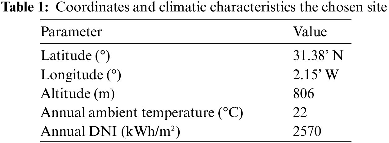
The selection of the location for the analysis is crucial to ensure the feasibility of the installed plant, and it must possess abundant solar energy resources, with levels exceeding 1800 kW/m2 annually [26]. In this study, the location chosen for the analysis is Bechar, situated in the South-West region of Algeria, as depicted in Fig. 1. Bechar is known for its sunny climate, with a daily mean solar radiation of approximately 7.04 kWh/m2/day. Table 1 provides the specific site coordinates, along with the ambient conditions and solar resources associated with Bechar [27].

Figure 1: The site where the simulations were conducted
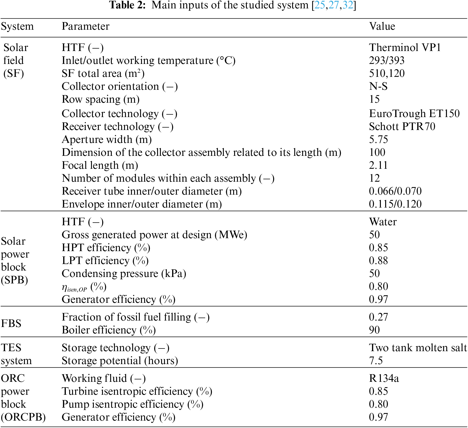
As mentioned earlier, a CSP plant integrated with an ORC for waste heat recovery will be simulated and its performances will be assessed. In this integrated structure, a combined layout will be employed, where a large field of East-to-West sun-tracking parabolic trough collectors of type EuroTrough ET150 will be used by the PTSPP [28], with an area of 510,120 m2. Each solar collector assembly measures 100 m × 5.75 m and is composed of 12 modules. The working fluid, which is Therminol VP1 in this project, circulates inside the receivers to absorb heat and then transfers it to a steam Rankine cycle, which produces superheated steam to generate electricity. Additionally, two auxiliaries have been included in the system to maintain high levels of power generation by the solar installation; thermal energy storage (TES) and fuel backup system (FBS) to raise the dispatch capacity during low-solar time.
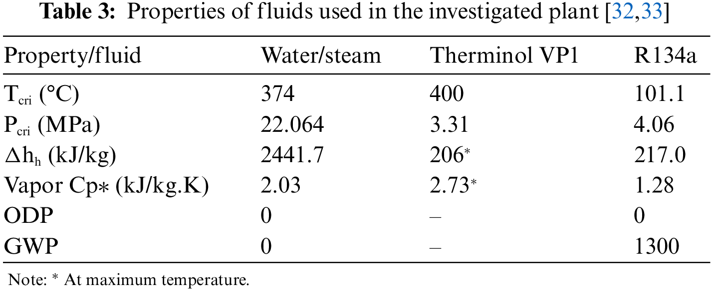
In contrast, a basic ORC is integrated as a lower-level cycle, where the condenser of the solar installation is used to reclaim heat and facilitate the cooling process by pumping cooling water through it. Subsequently, the cooling water transfers its heat to an organic fluid (the primary fluid in the ORC) in an evaporator. The electricity is then generated as in the conventional ORC configuration. The design in question is illustrated in Fig. 2, and its key parameters are presented in Table 2. Additionally, the thermo-physical characteristics of the heat transfer fluids employed in the examined design are summarized in Table 3.

Figure 2: Studied solar power plant with waste heat recovery installation
The mathematical model of the proposed solar plant is presented as a sub-system-wise formulation; including solar block with its Rankine power block and its two auxiliaries (TES and FBS), as well as the ORC heat recovery installation in subsequent sections.
The global efficiency of the SF, which refers to the ratio between the gained heat by the thermic oil (as the heat transfer fluid) and the total incident solar radiation on the global surface area of the solar plant, is expressed as follows:
where
In Eq. (2),
where the parameters appear in Eq. (3) are defined in the nomenclature, and present different optical losses in the solar field, and can be modeled as [29,30]:
Besides, the gained heat by the thermic oil is calculated as:
where
With
The solar block in this configuration is supplied with thermal energy storage and fuel backup systems, which improve the dispatch capacity of the installation. In the present model, we consider two specifications of these systems, as described in reference [30].
where
Fig. 2 shows that the power block is based on a regenerative Rankine cycle, which is modelled and simulated under off-design conditions using established correlations, as described in reference [34]:
For the mathematical model of the waste heat recovery system, a simple ORC layout has been chosen, where R134a is selected as the primary working fluid within the system. In this regard, mass and energy balances have been applied to each component of the system, and the corresponding equations are summarized in Table 4.
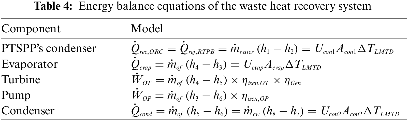
where
As mentioned in the introduction section, the main aim of the present study is to simulate the whole system under varying climatic conditions and levels of solar radiation, thus, the use of an off-design model is essential to ensure accurate performance assessment and avoid any miscalculations. The off-design model of the solar block has already been presented taking into account the correlations provided in SAM software. For the heat recovery system, the pump and turbine efficiencies, as well as the global heat transfer coefficients of the heat exchangers, were modeled according to [35]:
where:
The index d in these two equations denote to conditions at the design point.
On the other side, the Pump efficiency under off-design conditions is presented by [36]:
For the global heat transfer coefficients of the considered heat exchangers at off-design conditions, they are given by:
At the end, the energy efficiency and the capacity factor of the whole system with its integrated waste heat recovery system are evaluated by:
The current study focuses on conducting an economic analysis of the examined solar plant, which incorporates a waste heat recovery system. This analysis is primarily based on the LCOE, which serves as a widely utilized parameter in the techno-economic evaluation of various thermal power plants. The LCOE takes into account multiple factors, including the initial investment costs
With
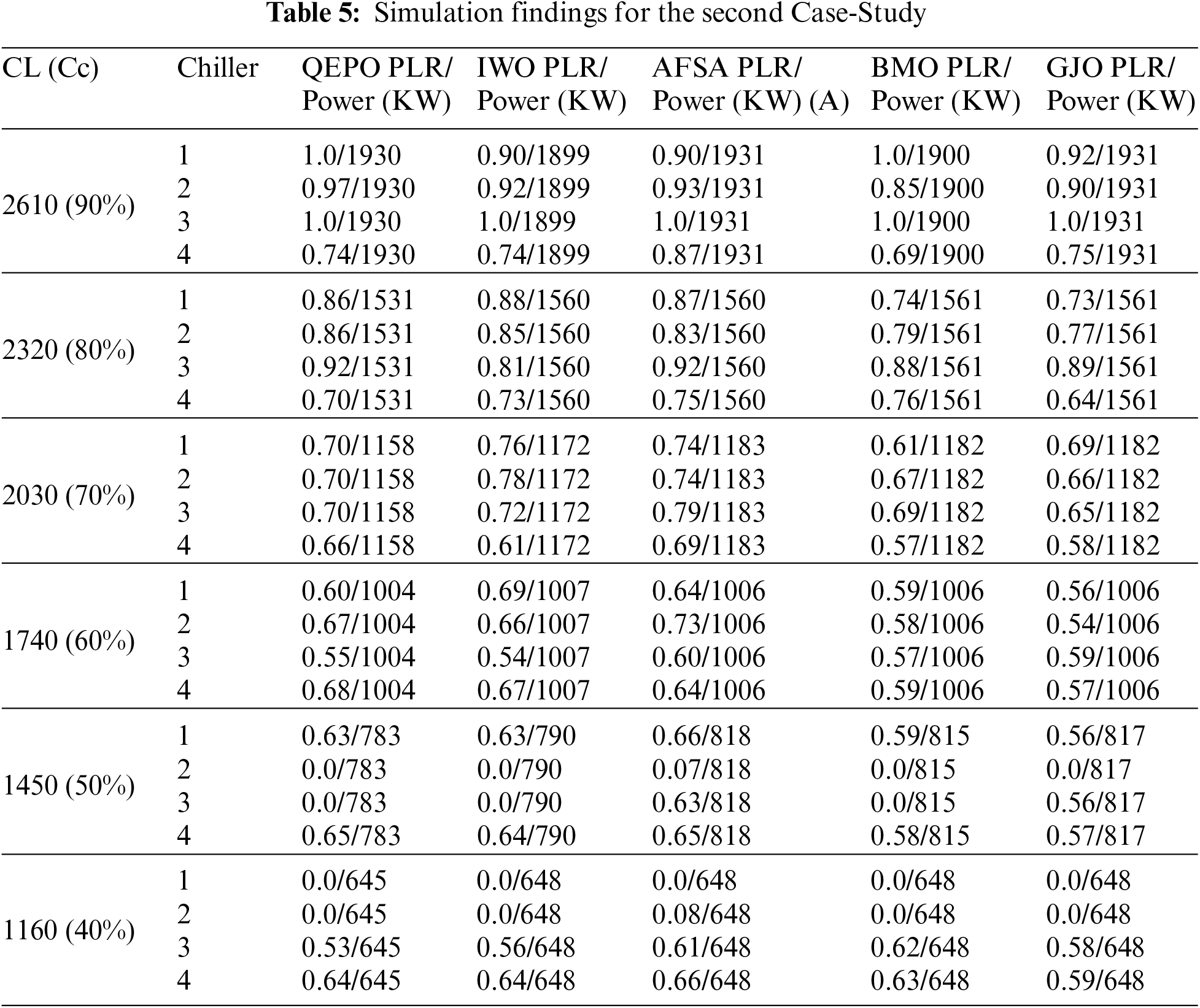
The annual discount rate kd used in this study is assumed to be 10.9% [32]. Additionally, the depreciation operation time of the plant (N) is set at 25 years. It is important to note that the total investment and operational and maintenance costs mentioned here have been calculated using data and correlations obtained from the literature. These specific inputs and equations are listed in Tables 5 and 6 for the PTPP and the ORC waste heat recovery system, respectively.

This study aims to investigate the integration of a waste heat recovery system into a parabolic trough power plant, and evaluate its performances compared to a conventional PTSPP, using Andasol 1 as a case study. The performances of both systems are simulated using the off-design model described in Section 2.4, and evaluated in terms of hourly and annual efficiencies and power generation. Table 7 provides a comparison of the annual yield of Andasol 1 conventional plant and the new plant with its integrated waste heat recovery system. Additionally, Figs. 3 and 4 show the mean hourly values of generated power and energy efficiencies for these two plants. Furthermore, Figs. 5 and 6 illustrate the hourly generated power of Andasol 1 and the new plant, respectively.
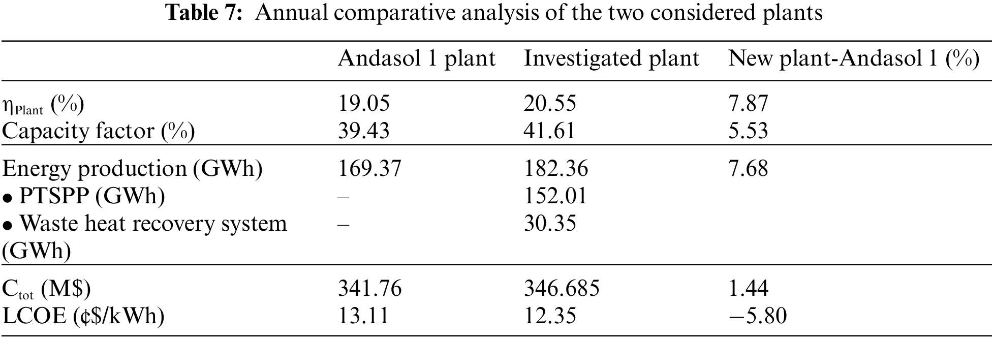

Figure 3: Annual mean hourly generated powers of the two layouts

Figure 4: Annual mean hourly efficiencies of the two layouts

Figure 5: Hourly generated power of the conventional Andasol 1 plant

Figure 6: Hourly generated power of the new plant with waste heat recovery system
It is widely acknowledged that one of the primary issues with CSP plants is the significant amount of heat lost during the cooling process of the steam in the power block. However, the new configuration with the waste heat recovery system provides a solution to this problem. This was achieved by using the bottoming ORC to convert a significant portion of the waste heat from the topping parabolic trough solar plant, thereby increasing the electricity production in the new system. In this new configuration, considerable part of waste heat from the RTPB is converted to electricity in the ORC. As shown in Table 7 and Fig. 3, the generated power of the entire plant has increased to almost 183 GWh annually, representing an increase rate of approximately 7.60% compared to the traditional Andasol 1 layout, which generated 169 GWh. The majority of this dispatch capacity comes from the solar power plant at a rate of almost 85%, while the remaining portion is generated by the waste heat recovery system, amounting to 30.35 GWh.
Transitioning to the economic aspect of the analyzed configuration, as outlined in Table 7, it is observed that the total investment cost of the new layout has increased from 341.76 to 346.68 M$. This increase amounts to a rate of 1.44%. The rise in investment cost can be primarily attributed to the expenses associated with the ORC heat recovery systems, which are further categorized into costs related to installation and costs linked to operation and maintenance.
When considering the most important parameter in analyzing the techno-economic performance of large-scale power plants, as evident from the comprehensive data provided in Table 7, it becomes apparent that the Levelized Cost of Electricity (LOCE) has undergone a noteworthy reduction rate of 5.8% in the new configuration (12.35 ¢$/kWh) compared to the classic plant Andasol 1 (13.11 ¢$/kWh), despite the increase in total investment cost. This intriguing finding can be justified by the remarkable increase in generated power throughout the year when compared to Andasol 1. The improved efficiency and enhanced performance of the new configuration have resulted in a higher power output, which, in turn, has led to a reduction in the Levelized Cost of Electricity.
Although the total investment cost has increased in the new configuration compared to Andasol 1, the economic benefits derived from the increased power generation outweigh the higher initial investment. This positive trade-off showcases the advantageous techno-economic performance of the new layout, making it a more viable and financially sound option. Therefore, the significant decrease of 5.8% in the Levelized Cost of Electricity (LOCE) in the new configuration, despite the higher investment cost, can be attributed to the substantial increase in generated power throughout the year compared to the classic plant Andasol 1.
Regarding the energy efficiency, which is presented as the proportion of the solar radiation incident on the entire surface area of the solar field that is converted into electrical energy. The efficiency of the investigated layout has increased to 20.55%. This represents a 7.87% increase compared to the traditional Andasol 1 layout, which has a global efficiency of 19.05%. The substantial increase in energy efficiency can be attributed to the higher power generation resulting from the ORC system, which has boosted the dispatch capacity of the whole plant.
On the other hand, if we focus on the performance of the studied plant on an hourly basis, we can observe differences in the annual mean hourly efficiency and generated power of the two configurations, as shown in Figs. 3 and 4. Specifically, from 9:00 to 12:00 a.m., there is a decrease in the differences of generated power and efficiency. This decline can be attributed to a decrease in the energy received by the waste heat recovery system from the RTPB, which leads to a lower amount of energy being converted to electricity by the ORC. In contrast, during the period from noon to late afternoon (12:00 to 18:00 p.m.), the yield differences increase due to the increase in thermal heat received by the solar power block, resulting in more energy being supplied to the ORBPB.
Another crucial aspect is exploring the year-round data of power generation for Andasol 1 (Fig. 4) and the plant with integrated waste heat recovery (Fig. 5). In the new configuration, the hourly generated power can reach a peak of almost 60 MW, with an additional 10 MW being produced by the incorporated waste heat recovery system, surpassing the nominal capacity of Andasol 1, which is 50 MW. However, one of the main weaknesses of solar thermal power plants, particularly those that use molten salt as a heat transfer fluid in the TES, is the energy required for HTF freeze protection. These power plants consume a large amount of energy to heat the working fluid and prevent it from freezing during the winter months (which can exceed 20 MW in November and December). To prevent this, the molten salt must be kept at a high temperature of over 220°C, which requires additional energy inputs. This energy requirement can significantly reduce the efficiency and power generation of the plant.
In the present study, the performances of a new combined CSP thermal power plant equipped with a waste heat recovery system have been evaluated and compared with those of an existing plant. The solar installation is based on a conventional parabolic trough power plant, like that of Andasol 1, with incorporated thermal storage and fuel backup systems. The waste heat recovery system is based on an organic Rankine cycle. To assess the performance of both systems, both hourly and annual thermodynamic performances were simulated using an off-design model. This model allows for a comprehensive evaluation of the plant's efficiency and power generation under different operating conditions and off-design scenarios.
In summary, the power generation of the plant has significantly increased, reaching nearly 183 GWh annually. Approximately 85% of this power is generated by the solar power plant, while the remaining portion is generated through the waste heat recovery system. The efficiency of the plant has notably improved, reaching 20.45%, which represents a remarkable 7.87% increase compared to the traditional layout (Andasol 1). This improvement can be attributed to the integration of an ORC system, which enhances the dispatch capacity of the entire plant. When analyzing the hourly performances of the new layout, notable differences in power generation and efficiency are observed compared to the traditional layout, especially during the time intervals from 9:00 a.m. to 12:00 p.m. and from 12:00 to 6:00 p.m. The new layout achieves a peak hourly power generation of nearly 60 MW, surpassing the nominal capacity of Andasol 1 by an additional 10 MW, thanks to the incorporation of the waste heat recovery system.
On the other hand, the new layout has achieved a reduction of over 5.8% in the LCOE compared to the Andasol 1 plant. Specifically, the LCOE has decreased from 13.11 to 12.35 c/kWh, highlighting the improved cost-effectiveness of the new layout in generating electricity.
It should be emphasized that this study represents a preliminary analysis, and further investigations are warranted in several directions. Firstly, to gain a comprehensive understanding of the system’s performance, an analysis based on the second law of thermodynamics is necessary. This analysis would provide valuable insights into the efficiency and entropy generation within the plant. Additionally, an environmental investigation is crucial to evaluate the positive effects of this configuration on both CO2 gas emissions and water consumption for the cooling process. Assessing the environmental impact and sustainability aspects will help determine the overall benefits and potential for mitigating greenhouse gas emissions and reducing water usage. Furthermore, it is highly recommended to carefully consider the selection process of the organic fluid in the bottoming ORC. Choosing the optimal candidates for the organic fluid will play a pivotal role in enhancing the techno-economic performance of this layout. Thorough research and analysis should be conducted to identify the most suitable organic fluids that can maximize efficiency, reduce costs, and ensure system reliability.
Acknowledgement: None.
Funding Statement: The authors received no specific funding for this study.
Author Contributions: The authors confirm contribution to the paper as follows: study conception and design: TE. Boukelia, A. Bourouis; data collection: ME. Abdesselem; analysis and interpretation of results: TE. Boukelia; draft manuscript preparation: TE. Boukelia, MS. Mecibah, A. Bourouis. All authors reviewed the results and approved the final version of the manuscript.
Availability of Data and Materials: Data supporting this study are included within the article.
Conflicts of Interest: The authors declare that they have no conflicts of interest to report regarding the present study.
References
1. Boukelia, T. E., Arslan, O., Mecibah, M. S. (2017). Potential assessment of a parabolic trough solar thermal power plant considering hourly analysis: ANN-based approach. Renewable Energy, 105, 324–333. [Google Scholar]
2. Mahmoudi, A., Fazli, M., Morad, M. R. (2018). A recent review of waste heat recovery by organic Rankine cycle. Applied Thermal Engineering, 143, 660–675. [Google Scholar]
3. Anastasovski, A., Rasković, P., Guzović, Z. (2020). A review of heat integration approaches for organic Rankine cycle with waste heat in production processes. Energy Conversion and Management, 221, 113175. [Google Scholar]
4. Khaljani, M., Saray, R. K., Bahlouli, K. (2015). Thermodynamic and thermoeconomic optimization of an integrated gas turbine and organic Rankine cycle. Energy, 93, 2136–2145. [Google Scholar]
5. Sadeghi, M., Chitsaz, A., Marivani, P., Yari, M., Mahmoudi, S. M. S. (2020). Effects of thermophysical and thermochemical recuperation on the performance of combined gas turbine and organic Rankine cycle power generation system: Thermoeconomic comparison and multi-objective optimization. Energy, 210, 118551. [Google Scholar]
6. Koç, Y., Yağlı, H., Kalay, I. (2020). Energy, exergy, and parametric analysis of simple and recuperative organic Rankine cycles using a gas turbine-based combined cycle. Journal of Energy Engineering, 146(5), 04020041. [Google Scholar]
7. Tian, Z., Zeng, W., Gu, B., Zhang, Y., Yuan, X. (2021). Energy, exergy, and economic (3E) analysis of an organic Rankine cycle using zeotropic mixtures based on marine engine waste heat and LNG cold energy. Energy Conversion and Management, 228, 113657. https://doi.org/10.1016/j.enconman.2020.113657 [Google Scholar] [CrossRef]
8. Georgousopoulos, S., Braimakis, K., Grimekis, D., Karellas, S. (2021). Thermodynamic and techno-economic assessment of pure and zeotropic fluid ORCs for waste heat recovery in a biomass IGCC plant. Applied Thermal Engineering, 183, 116202. https://doi.org/10.1016/j.applthermaleng.2020.116202 [Google Scholar] [CrossRef]
9. Mohammadi, A., Ashouri, M., Ahmadi, M. H., Bidi, M., Sadeghzadeh, M. et al. (2018). Thermoeconomic analysis and multiobjective optimization of a combined gas turbine, steam, and organic Rankine cycle. Energy Science & Engineering, 6(5), 506–522. [Google Scholar]
10. Ansari, S. A., Khalid, M., Kamal, K., Abdul Hussain Ratlamwala, T., Hussain, G. et al. (2021). Modeling and simulation of a proton exchange membrane fuel cell alongside a waste heat recovery system based on the organic Rankine cycle in MATLAB/SIMULINK environment. Sustainability, 13(3), 1218. [Google Scholar]
11. Zhao, P., Wang, D., Zhou, D., Zhang, H., Sun, Y. (2020). Thermal analysis of the transcritical organic Rankine cycle using R1234ze (E)/R134a mixtures as working fluids. Energy Engineering, 117(4), 209–224. https://doi.org/10.32604/EE.2020.010567 [Google Scholar] [CrossRef]
12. Ozahi, E., Abusoglu, A., Tozlu, A. (2021). A comparative thermoeconomic analysis and optimization of two different combined cycles by utilizing waste heat source of an MSWPP. Energy Conversion and Management, 228, 113583. [Google Scholar]
13. Li, B., Wang, S. S., Wang, K., Song, L. (2021). Comparative investigation on the supercritical carbon dioxide power cycle for waste heat recovery of gas turbine. Energy Conversion and Management, 228, 113670. [Google Scholar]
14. Yağlı, H., Koç, Y., Kalay, H. (2021). Optimisation and exergy analysis of an organic Rankine cycle (ORC) used as a bottoming cycle in a cogeneration system producing steam and power. Sustainable Energy Technologies and Assessments, 44, 100985. [Google Scholar]
15. Liu, X., Nguyen, M. Q., Chu, J., Lan, T., He, M. (2020). A novel waste heat recovery system combing steam Rankine cycle and organic Rankine cycle for marine engine. Journal of Cleaner Production, 265, 121502. [Google Scholar]
16. Tontu, M., Sahin, B., Bilgili, M. (2020). An exergoeconomic–environmental analysis of an organic Rankine cycle system integrated with a 660 MW steam power plant in terms of waste heat power generation. Energy Sources, Part A: Recovery, Utilization, and Environmental Effects, 1–22. [Google Scholar]
17. Luo, L., Fan, Y., Wang, Y., Ni, P., Zhang, W. et al. (2022). Experiment study on the exhaust-gas heat exchanger for small and medium-sized marine diesel engine. Energy Engineering, 120(1), 125–145. https://doi.org/10.32604/ee.2022.022295 [Google Scholar] [CrossRef]
18. Mariani, A., Laiso, D., Morrone, B., Unich, A. (2023). Exergy analysis of organic Rankine cycles with zeotropic working fluids. Fluid Dynamics & Materials Processing, 19(3), 593–601. https://doi.org/10.32604/fdmp.2022.022524 [Google Scholar] [CrossRef]
19. Zhang, H., Liu, Y., Liu, X., Duan, C. (2020). Energy and exergy analysis of a new cogeneration system based on an organic Rankine cycle and absorption heat pump in the coal-fired power plant. Energy Conversion and Management, 223, 113293. [Google Scholar]
20. Al-Rawashdeh, H. A., Gomaa, M. R., Mustafa, R. J., Hasan, A. O. (2019). Efficiency and exergy enhancement of ORC powered by recovering flue gases-heat system in cement industrials: A case study. International Review of Mechanical Engineering, 13, 185–197. [Google Scholar]
21. Gomaa, M. R., Mustafa, R. J., Al-Dhaifallah, M., Rezk, H. (2020). A low-grade heat organic Rankine cycle driven by hybrid solar collectors and a waste heat recovery system. Energy Reports, 6, 3425–3445. [Google Scholar]
22. Sachdeva, J., Singh, O. (2021). Comparative evaluation of solarized triple combined cycle for different ORC fluids. Renewable Energy, 163, 1333–1342. [Google Scholar]
23. Zoghi, M., Habibi, H., Choubari, A. Y., Ehyaei, M. A. (2021). Exergoeconomic and environmental analyses of a novel multi-generation system including five subsystems for efficient waste heat recovery of a regenerative gas turbine cycle with hybridization of solar power tower and biomass gasifier. Energy Conversion and Management, 228, 113702. [Google Scholar]
24. Habibi, H., Zoghi, M., Chitsaz, A., Javaherdeh, K., Ayazpour, M. et al. (2020). Working fluid selection for regenerative supercritical Brayton cycle combined with bottoming ORC driven by molten salt solar power tower using energy-exergy analysis. Sustainable Energy Technologies and Assessments, 39, 100699. [Google Scholar]
25. Giostri, A., Binotti, M., Astolfi, M., Silva, P., Macchi, E. et al. (2012). Comparison of different solar plants based on parabolic trough technology. Solar Energy, 86(5), 1208–1221. [Google Scholar]
26. Steinhagen, H. M., Trieb, F. (2004). Concentrating solar power—A review of the technology. Ingenia, 18, 43–50. [Google Scholar]
27. Boukelia, T. E., Ghellab, A., Laouafi, A., Bouraoui, A., Kabar, Y. (2020). Cooling performances time series of CSP plants: Calculation and analysis using regression and ANN models. Renewable Energy, 157, 809–827. [Google Scholar]
28. Boukelia, T. E., Mecibah, M. S. (2015). Estimation of direct solar irradiance intercepted by a solar concentrator in different modes of tracking (case study: Algeria). International Journal of Ambient Energy, 36(6), 301–308. [Google Scholar]
29. Wagner, M. J., Gilman, P. (2011). Technical Manual for the SAM Physical Trough Model (No. NREL/TP-5500-51825). USA: National Renewable Energy Laboratory (NREL). https://www.nrel.gov/docs/fy11osti/51825.pdf (accessed on 03/03/2023) [Google Scholar]
30. Dudley, V. E., Kolb, G. J., Mahoney, A. R., Mancini, T. R., Matthews, C. W. et al. (1994). Test Results: SEGS LS-2 Solar Collector. USA: Sandia National Laboratories http://www.nrel.gov/csp/troughnet/pdfs/segs_ls2_solar_collector.pdf [Google Scholar]
31. Forristall, R. (2003). Heat transfer analysis and modeling of a parabolic trough solar receiver implemented in engineering equation solver. Technical Report NREL/TP-550-34169. National Renewable Energy Laboratory, Golden, Colorado, USA. https://www.nrel.gov/docs/fy04osti/34169.pdf (accessed on 03/03/2023) [Google Scholar]
32. Boukelia, T. E., Arslan, O., Djimli, S., Kabar, Y. (2023). ORC fluids selection for a bottoming binary geothermal power plant integrated with a CSP plant. Energy, 265, 126186. [Google Scholar]
33. Eastman Corporate (2019). https://www.eastman.com/Literature_Center/T/TF9141.pdf [Google Scholar]
34. Wagner, M. J. (2010). Methodology for Constructing Reduced-Order Power Block Performance Models for CSP Applications: Preprint (No. NREL/CP-5500-49370). National Renewable Energy Lab. (NRELUSA. https://www.nrel.gov/docs/fy11osti/49370.pdf [Google Scholar]
35. Ghasemi, H., Paci, M., Tizzanini, A., Mitsos, A. (2013). Modeling and optimization of a binary geothermal power plant. Energy, 50, 412–428. [Google Scholar]
36. Hu, S., Li, J., Yang, F., Yang, Z., Duan, Y. (2020). Thermodynamic analysis of serial dual-pressure organic Rankine cycle under off-design conditions. Energy Conversion and Management, 213, 112837. [Google Scholar]
37. Quoilin, S., Declaye, S., Tchanche, B. F., Lemort, V. (2011). Thermo-economic optimization of waste heat recovery organic Rankine cycles. Applied Thermal Engineering, 31(14–15), 2885–2893. [Google Scholar]
38. Lecompte, S., Huisseune, H., van den Broek, M., de Schampheleire, S., de Paepe, M. (2013). Part load based thermo-economic optimization of the organic Rankine cycle (ORC) applied to a combined heat and power (CHP) system. Applied Energy, 111, 871–881. [Google Scholar]
39. Alshammari, F., Karvountzis-Kontakiotis, A., Pesyridis, A., Usman, M. (2018). Expander technologies for automotive engine organic Rankine cycle applications. Energies, 11(7), 1905. [Google Scholar]
40. Hu, S., Yang, Z., Li, J., Duan, Y. (2021). Thermo-economic optimization of the hybrid geothermal-solar power system: A data-driven method based on lifetime off-design operation. Energy Conversion and Management, 229, 113738. [Google Scholar]
Cite This Article
 Copyright © 2023 The Author(s). Published by Tech Science Press.
This work is licensed under a Creative Commons Attribution 4.0 International License , which permits unrestricted use, distribution, and reproduction in any medium, provided the original work is properly cited.
 Downloads
 Citation Tools