
 Submit a Paper
 Propose a Special lssue
 Open Access
ARTICLE

Simulation Study of the Control Strategy of a DC Inverter Heat Pump Using a DC Distribution Network
1 State Grid (Suzhou) City and Energy Research Institute, Suzhou, China
2 Electric Power Research Institute of State Grid Beijing Electric Power Company, Beijing, China
* Corresponding Author: Siwei Han. Email:
Energy Engineering 2023, 120(6), 1421-1444. https://doi.org/10.32604/ee.2023.027094
Received 13 October 2022; Accepted 09 January 2023; Issue published 03 April 2023
 View Full Text
 Download PDF
Abstract
Photovoltaics, energy storage, direct current and flexibility (PEDF) are important pillars of achievement on the path to manufacturing nearly zero energy buildings (NZEBs). HVAC systems, which are an important part of public buildings, play a key role in adapting to PDEF systems. This research studied the basic principles and operational control strategies of a DC inverter heat pump using a DC distribution network with the aim of contributing to the development and application of small DC distribution systems. Along with the characteristics of a DC distribution network and different operating conditions, a DC inverter heat pump has the ability to adapt to changes in the DC bus voltage and adds flexibility to the system. Theoretical models of the DC inverter heat pump integrated with an ice storage unit were developed. The control strategies of the DC inverter heat pump system considered the influence of both room temperature and varied bus voltage. A simulation study was conducted using MATLAB & Simulink software with simulation results validated by experimental data. The results showed that: (1) The bus fluctuation under the rated working voltage had little effect on the operation of the unit; (2) When the bus voltage was fluctuating from 80%–90% or 105%–107%, the heat pump could still operate normally by reducing the frequency; (3) When the bus voltage was less than 80% or more than 107%, the unit needed to be shut down for the sake of equipment safety, so that the energy storage device could adjust to the sharp decrease or rise of voltage.Keywords
Nomenclature
| RES | Renewable energy sources |
| PVs | Photovoltaics |
| STCs | Solar thermal collectors |
| DHW | Domestic hot water |
| HPs | Heat pumps |
| BES | Battery energy storage |
| TES | Thermal energy storage |
| PEDF | Photovoltaics, energy storage, direct current and flexibility |
| HVAC | Heating ventilation air conditioning |
| ASHP | Air source heating pump |
| ITS | Ice thermal storage |
| PI | Proportional-integral |
| m | Refrigerant mass flow, kg/s |
| f | Frequency, Hz |
| W | Power, kW |
| h | Enthalpy, kJ/kg |
| Q | Cooling Capacity, kW |
| n | Speed, rps |
| c | Specific heat capacity |
| K | Heat transfer coefficient, W/(m2 |
| A | Area, m2 |
| t | Temperature, °C |
| C | Discharge coefficient |
| P | Pressure, Pa |
| G | Air supply volume, kg/s |
| D | Outer diameter of impeller, m |
| L | The impeller length, m |
| p | Number of motor poles |
| V | Voltage, V |
Greek symbols
| ν | Suction volume |
| Φ | Opening degree, % |
| η | Efficiency, % |
| λ | Area utilization of the fan, % |
| τ | Time |
Subscripts
| Com | Compressor |
| Dis | Discharge |
| Suc | Suck |
| w | Water |
| cw | Cooling water |
| Cond | Condenser |
| rc | Refrigerant side |
| c | Condensation |
| ex | Expansion valve |
| Is | Ice |
| Out | Outdoor |
| In | Indoor |
| Hu | Human |
| s | Air supply |
| m | DC bus |
| ref | Reference |
When it comes to the demand for heating and cooling, residential buildings have the potential to become energy efficient, and accordingly reduce emissions. Existing and new buildings should be characterized by nearly zero or very low energy supplied by the grid, and thus their thermal and electrical energy needs should be controlled by energy systems of high efficiency [1,2]. The main goal of an energy system is to combine renewable energy sources (RES) and other assets, e.g., storage and generation units of thermal or electrical energy, whose synergies are appropriately coupled, to increase the overall system efficiency [3]. Among the various RES technologies, growing trends include solar Photovoltaics (PVs) for electricity and solar thermal collectors (STCs) for DHW (domestic hot water) [4]. PVs coupled with electrical drive systems, such as heat pumps (HPs) are also used for DHW generation, space heating and cooling. The intermittent nature of solar energy that reaches PVs combined with variable building energy demands makes flexible sources of storage such as battery energy storage (BES) and thermal energy storage (TES) a necessity in managing building energy demands. Flexibility improves the overall efficiency of the system and increases the electricity bill savings [5,6]. Although mostly single-speed HPs are installed in residencies, variable speed units can provide additional flexibility in power consumption by modulating the compressor speed [7,8].
Energy assets should be optimally co-scheduled to achieve the expected performance in terms of energy balance, thermal comfort, grid friendliness and life-cycle costs [9,10]. In response to the rapid growth of carbon emissions worldwide [11], China issued the ‘Peak Carbon Dioxide Emissions Action Plan before 2030’ in October 2021. Buildings with photovoltaics, energy storage, direct current and flexibility (PEDF) have begun to enter the public view. As a new energy system, buildings with PEDF are key to achieve the 2060 carbon neutralization goal in the construction and operation stages. The results of research on new energy systems with PEDF will provide important technical information in the consultation, design, operation and maintenance of low-carbon buildings in the future, and help the construction industry form technical reserves in the carbon neutralization field.
However, the lack of suitable DC equipment has created a bottleneck in the practical application of PEDF for construction and engineering firms. The development of a supply-side and demand-side in PEDF systems will provide favourable conditions for the development of a low-pressure DC distribution system. In a traditional AC distribution network, it is necessary to convert AC power into DC power for electromechanical equipment to run efficiently. A DC distribution system, however, eliminates the need for an AC-DC conversion link. The system is simpler and already allows electrical equipment to run efficiently. Fluctuations in wind power and photovoltaics enables the load side to change its power generation while accessing a large-scale power grid which has the means to regulate and cope with fluctuations. The large grid issues power instructions to the AC/DC device in the DC distribution network according to real-time power supply and demand. The DC device in the DC distribution network regulates its use of power use based on the change in bus voltage, which enables the DC distribution network to meet the power needs and instructions issued by the grid, thus helping the grid maintain the supply and demand balance and improving the dissipation capacity of renewable energy [12].
In building a PEDF system, a heating ventilation air conditioning (HVAC) system is regarded as ideal for the following two reasons: First, HVAC systems are electrically powerful. For example, the ratio of power in an HVAC system to total power in a utility building can be greater than 30%. Second, the thermal properties of HVAC systems make them naturally electrically flexible. Due to the thermal inertia of a building enclosure, the air conditioning system, even if it runs briefly to reduce the load, does not significantly affect the sensation of a user’ body. In addition, in combination with inexpensive heating and cooling storage devices, an air conditioning system can achieve even greater electrical flexibility.
A heat pump is an efficient mechanical device that produces low-polluting heating energy using renewable energy sources such as solar energy, ambient air energy, geothermal energy or waste heat [13–15]. In order for an HVAC system to function in a building with PEDFs, it is essential to develop a matching DC inverter heat pump. Because of this, DC inverter heat pumps have attracted increasing attention from researchers in recent years. Liu et al. [16] introduced the DC inverter to a heat pump water heater system, and mathematical equations for the exchanger and evaporator were proposed to describe the compressor. Optimal parameters were verified using experimental methods for measuring heat transfer performance. The refrigerant charge quantity was optimized by the model and experimental data. Taking into account the influence of the energy efficiency ratio and output heating and output water on the system performance, the optimal length of the capillary tube was 0.65 mm for the DC inverter heat pump water heater system. Wang et al. [17] proposed an injection-assisted air source heat pump (ASHP) using a novel two-stage variable-speed scroll compressor with a variable volume ratio and direct current (DC) speed regulation motor, named IDCAHP, for improving heating performance in cold and/or severely cold regions over wide-range temperature conditions. Experiments focusing on the heating performance of the IDCAHP under different temperatures and frequency were conducted. Results indicated that the IDCAHP performed well over a wide-range temperature condition. Lyu et al. [18] established a model of an energy storage heating system on the TRNSYS platform and validated it with data that was monitored long-term. The influence of the size of the water storage tank and the size of the air source heat pump on the energy saving potential of the energy storage heating system was investigated. Zanetti et al. [19] proposed an approach that combined existing gas boilers with phase change material storages (PCM) and a direct current air source heat pump (DC-EHP) assisted by a photovoltaic system (PV) connected to the grid. A state-of-the-art rule-based controller was developed that combined TRNSYS with a MATLAB script and was tested against an interior point optimal control algorithm. Roccatello et al. [20] studied primary energy (PE) consumption obtained by comparing dynamic simulations and discovered that the most efficient control strategies were those that maximized heat pump utilization. Ma et al. [21] studied the effects of commonly used PV/T system control strategies on the performance of liquid-based PV/T assisted heat pumps. Models of liquid-based PV/T assisted heat pumps with three different PV/T system control strategies were developed using a combination of the platforms of EES and TRNSYS.
Previous literature indicates that the applications of the variable speed heat pump have been increasing at an accelerating pace in recent years. Neither readily used products nor enough research information exists on heat pumps that can achieve satisfactory indoor thermal comfort while mitigating the fluctuation issue of DC distribution network. The strategies to control variable speed heat pumps integrated with renewable energy such as PV are crucial for the stability and effectiveness of the integrated system remain unstudied. In order to make up for the lack of previous research in this field, this study proposed a variable speed heat pump integrated with an ice storage unit which can directly use a DC distribution network. Theoretical models of a system that included a heat pump model, an ice storage unit model and a room model were developed. The control strategies of the integrated system considered both room temperature and varied DC bus voltage. A simulation study was conducted using MATLAB & Simulink software. The results were validated with experimental data from real heat pumps. The influence of the voltage on the stability of the system was compared and analysed under cooling and heating working conditions. The results show that despite the fluctuation of the bus voltage, the DC heat pump unit can provide sufficient energy for the room.
2 Control Strategy of the DC Inverter Heat Pump System
The schematic diagram of the DC inverter heat pump system model investigated in this paper is shown in Fig. 1, which includes the DC heat pump using a frequency conversion compressor, plate heat exchanger and frequency conversion fan. In order to manage the fluctuation of DC bus voltage and efficiently use the whole system, an ice storage module was added to manage the indoor load when the DC heat pump set failed to run normally.
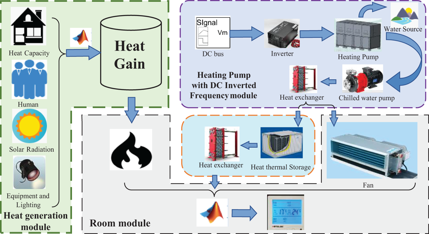
Figure 1: Schematic diagram of the DC inverter heat pump system
2.1 Control Strategy of the Compressor
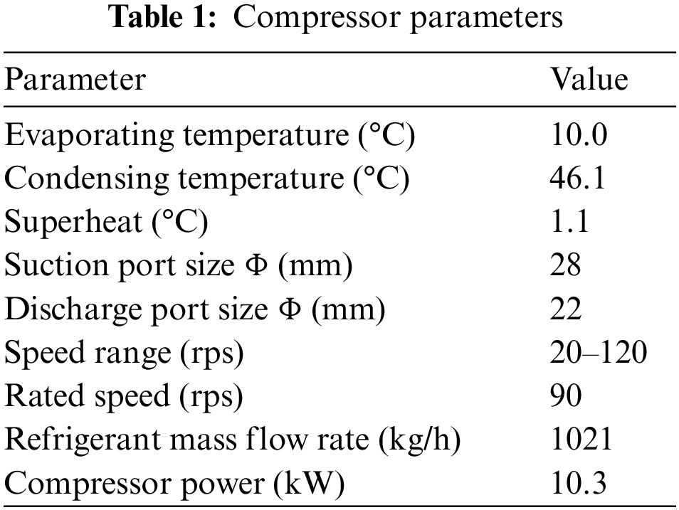
Compressor operation is determined by both indoor load and DC bus voltage. Fig. 2 shows a schematic diagram of the control logic of the compressor, Fig. 3 shows the speed adjustment of the compressor at the mode conversion and Table 1 shows the parameters of the compressor. During the normal operation stage, the compressor frequency was adjusted according to the indoor load to achieve the condition in which the cold generated by the compressor was level with the load. When the DC bus voltage fluctuated significantly in a short time, because the compressor stopped and restarted in a short time, the suction and exhaust pressure failed to immediately balance. The compressor withstood a large pressure difference to start. Improper control led to an overload or step loss, and the compressor could not be started. The frequency at start up was boosted by 2 Hz/s, and a wait period of at least 3 min allowed the compressor to heat up sufficiently while preventing lubricant in the compressor from flowing into the refrigeration system. During normal operation, frequency conversion was enabled according to the load change in the room. It was important to note the lower limit of frequency conversion. The fluctuation of speed in low frequency, which may increase vibration and stress in the piping, can shorten the compressor’s lifetime [22]. When the compressor received the shutdown command, it was necessary to first reduce the frequency at a rate of 2 Hz/s. When the voltage of the DC bus exceeded the safe working range, in order to avoid damage to the equipment and ensure safety in subsequent use, it was necessary to perform a rapid shutdown of the compressor.
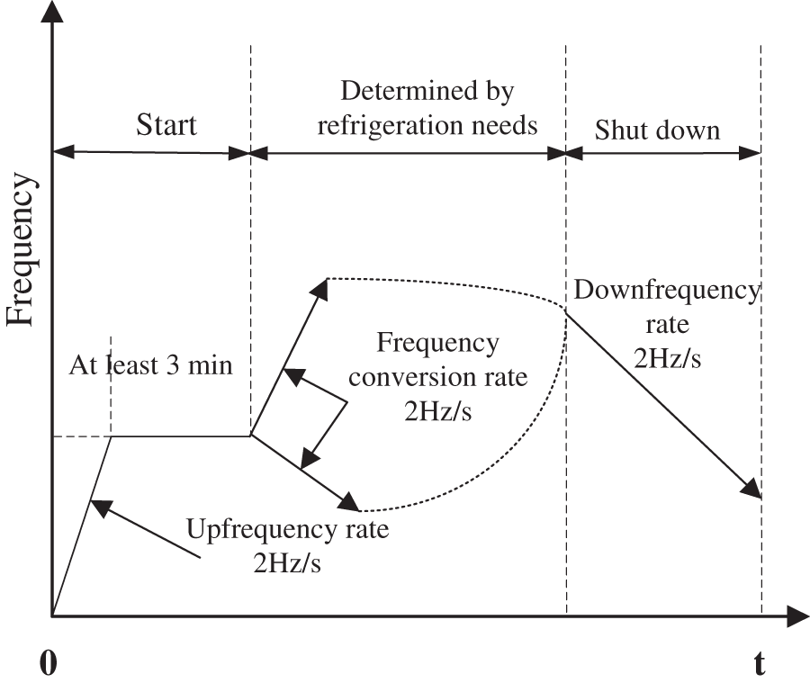
Figure 2: Control logic diagram of the compressor
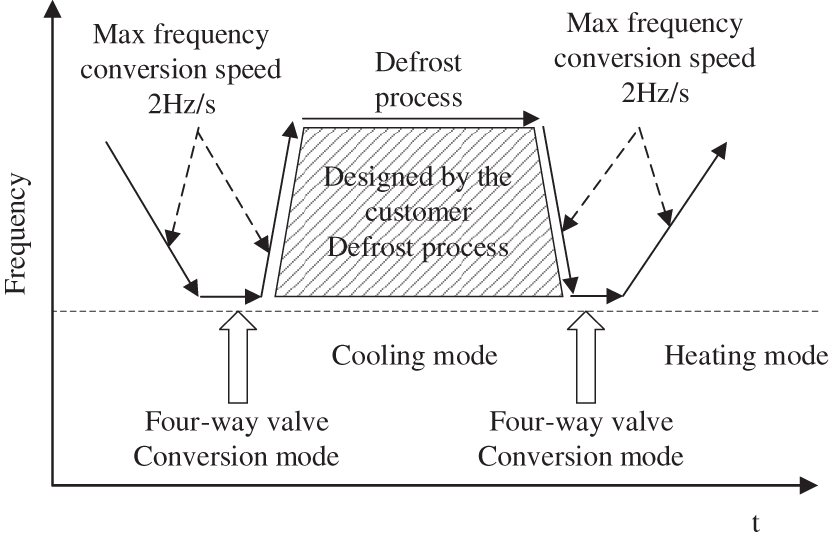
Figure 3: Speed adjustment of the compressor during mode conversion
2.2 Control Strategy of the Fan
The fan and compressor operating frequency is linked: when the indoor load is large, the compressor should increase the frequency to match the increased cooling capacity, while increasing the frequency of the fan; when the strong mode is turned on, the indoor air supply speed increases, and the frequency of fan and compressor also increases together. The specific control strategy is shown in Fig. 4. When the compressor frequency was low in normal working mode, the fan also maintained the minimum working frequency; when the user wanted to increase the air supply speed or cooling capacity, the compressor and fan frequency increased together until reaching the maximum working frequency.
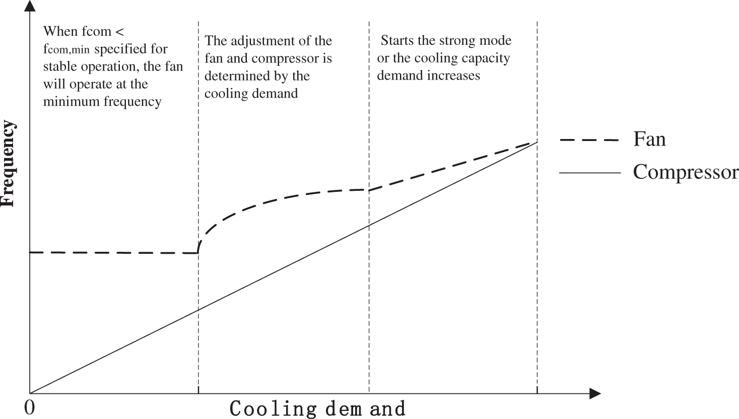
Figure 4: Control strategy of the fan
2.3 Control Strategy of the Ice Thermal Storage Module
The ice thermal storage system is used to transfer peak load and reduce cost in buildings, and its control strategy can greatly affect the economy of the system. Hajiah et al. [23,24] reported that the ice thermal storage (ITS) system can resolve both the peak-valley difference increasing and the mismatch problems due to the fact that the time of generation of cooling energy is separated from the time of its use. The ice thermal storage and control strategy is shown in Fig. 5. The ice storage period was 23:00 to 6:00. When the DC inverter heat pump set operated during the day, the ice storage system at night supplemented the load generated in the room during the period when the heat pump did not operate due to the DC bus voltage fluctuation, ensuring stability of the indoor temperature.
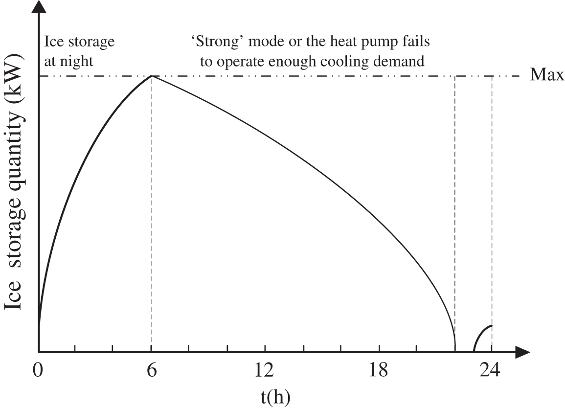
Figure 5: Control strategy of the ice storage system
2.4 Control Strategy of the DC Inverter Heat Pump
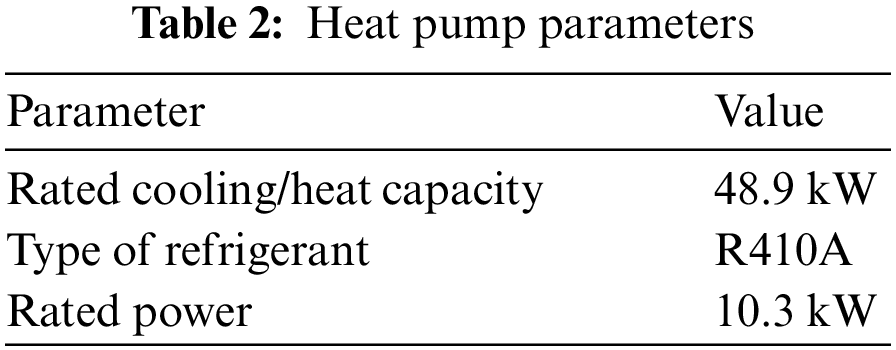
Liao et al. [25] summarized that traditional control strategies for heat pump system include: total cooling load-based sequencing control, return water temperature-based sequencing control, bypass flow-based sequencing control, and direct power-based sequencing control. The DC inverter heat pump control strategy in this paper was a load-based sequencing control, and the control flowchart is shown in Fig. 6. The input parameters include room temperature, bus voltage and air supply temperature. The corresponding compressor operation mode was selected after judging the bus voltage range. When the bus voltage was within 90%–105% of the rated voltage range, the equipment was able to operate normally according to its technical indicators and functions. When the DC bus voltage exceeded 90%–105% rated voltage range and was still within 80%–107% of the rated voltage range, the equipment could operate at reduced frequency. In other cases, the DC inverter heat pump set will stop the machine and the system will use the ice storage to supply cooling to the indoors. The heat pump set parameters used are shown in Table 2.
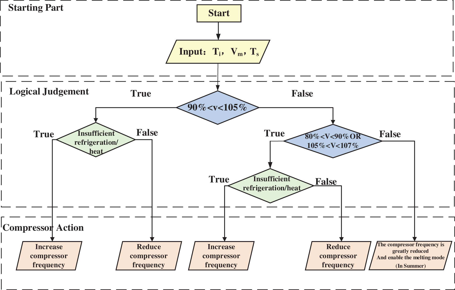
Figure 6: Flowchart of the control strategy for the DC inverter heat pump
In this study, MATLAB & Simulink software were used to establish the DC inverter heat pump system model, which included the following four parts: the DC inverter heat pump model, the ice storage system model, the room model, and the control logic model. The DC heat pump was composed of a compressor, condenser, expansion valve and evaporator. The ice thermal storage included an ice storage tank and an ice making and melting plate heat exchanger. The input parameters included compressor frequency, inspiratory temperature and inspiratory exhaust pressure. The final output cold volume was input into the room model module for calculation. By incorporating the four models in MATLAB & Simulink software with intermediate variables such as cooling capacity of heat pump, the relationships among real room temperature, frequency of compressor, and DC bus voltage can be analysed.
A dynamic model of a heat pump, which consisted of a compressor, a condenser, an electronic expansion valve and an evaporator, was built. The model assumed that the heat transfer process of each part of the heat pump was one-dimensional, stable and insulated. The four parts are as follows:
1) Compressor
As the heart of the heat pump, the compressor provides power for the whole system. The relationship between refrigerant flow and the frequency of the compressor is obtained by fitting the relationship between refrigerant flow and compressor speed given by the manufacturer.
where fcom is the compressor frequency.
The input work of compressor can be calculated by [26]
where hsuc is the specific enthalpy of the refrigerant at the compressor suction inlet; hdis is the specific enthalpy of the refrigerant at the compressor discharge outlet, which can be obtained by
where hdis is the ideal specific enthalpy of the refrigerant at the compressor discharge outlet under the isentropic compression condition; ηis is the isentropic efficiency of the compressor.
The refrigerating capacity of the DC variable frequency compressor used in the heat pump unit has a linear relationship with the speed; Eq. (4) shows that the power consumption also increases linearly. The refrigerating capacity of the compressor can be calculated by
where hsuc is the specific enthalpy of the refrigerant at the compressor suction inlet; hdis is the specific enthalpy of the refrigerant at the compressor discharge outlet; ν is the specific volume of gas at suction port of compressor; and Q1 is the refrigerating capacity of compressor, which can be calculated by
where ncom is the speed of the compressor; and νcom is the suction volume of the compressor.
2) Condenser
The condenser is located at the high-temperature and high-pressure end of the heat pump system. In the condenser, the high-temperature and high-pressure refrigerant gas exchanges with the cooling water to release heat, and the gas refrigerant is condensed into liquid.
The heat exchange on the water side of the condenser can be written as
where cw is the specific heat capacity of water at constant pressure; mw is the mass flow of water, tcw,in is the inlet temperature of cooling water; and tcw,out is the outlet temperature of cooling water.
The heat exchange on the refrigerant side of the condenser can be calculated by
where Kc is the convective heat transfer coefficient at the condenser side; Ac is the total heat exchange area of the condenser; hcon,in is the specific enthalpy of refrigerant at condenser inlet; hcon,out is the specific enthalpy of the refrigerant at the condenser outlet; and
where tc is the condensation temperature; tcw,in is the inlet temperature of the cooling water; and tcw,out is the outlet temperature of the cooling water.
The heat transfer balance on the condenser side can be written as
where Qw is the heat exchange on the water side of the condenser; and Qrc is the heat exchange on the refrigerant side of the condenser.
3) Expansion valve
The expansion process is considered to be isenthalpic, and thus the refrigerant mass flow rate across the expansion valve can be written as [27]
where Cev is the discharge coefficient of the expansion valve provided by the manufacturer; ρev,in is the refrigerant density at the valve inlet, Pev,in and Pev,out are the inlet and outlet pressures of the expansion valve, respectively; and Aev is the effective passage flow area of the expansion valve, which is [28]
where ϕex is the opening degree of the expansion valve and ranges from 0% to 100%; and Aex is the nominal orifice cross sectional area of the expansion valve.
4) Evaporator
Modelling method involving the evaporator are similar to that of the condenser and therefore will not be described in detail in this paper.
3.2 Ice Thermal Storage (ITS) Model
The focus of the ice storage system was to address the insufficient cold supply of the heat pump unit caused by the voltage fluctuation of the DC bus with only two modes: the energy storage mode and the energy release mode. The model of the ice storage tank is
where Eis,t and Mis,t represent the ice storage capacity and melting volume of the ice storage system, respectively; ηis indicates the ice making efficiency of the ice storage system; and Pis,t is the output of ice maker at time.
According to the Law of Conservation of Energy, the total heat gain of indoor environment resulted from heat gain through building envelope, indoor occupants, and air-conditioning system can be calculated by Eq. (13).
where tout is the outdoor temperature; tin is the indoor temperature; Ca is the specific heat ratio of air; mF is the air quality in the room; and Qhu is heat brought by people. Gs is the air supply rate which can be calculated as
where Gs is the air supply volume of the fan; D is the outer diameter of the impeller; L is the impeller length; λ is the area utilization of the fan; ffan is the fan frequency; s is the speed difference; P means the number of motor poles and n expresses the speed of fan.
The control block diagram of the DC inverter heat pump with DC bus voltage as input is shown in Fig. 7. The control system adopted a dual-loop proportional-integral (PI) control structure, in which the outer loop controller was responsible for generating power reference values while the inner loop controller was responsible for generating inverter frequency commands. Tset represents the set temperature of the room, Vref represents the nominal value of the DC bus voltage, Vm is the difference between the measured value of the DC bus voltage, and Vm and Vref was input into the outer loop PI controller to generate the reference power value Pref. The difference between the Pref and the measured power P of the unit was input into the inner loop controller, and the frequency command was generated and input into the inverter, which outputs AC waves to change the power of the compressor.
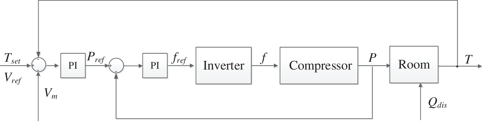
Figure 7: Control logic of the DC inverter heat pump
As shown in Fig. 8, the DC inverter heat pump simulation model can be established by modelling the four parts described above.
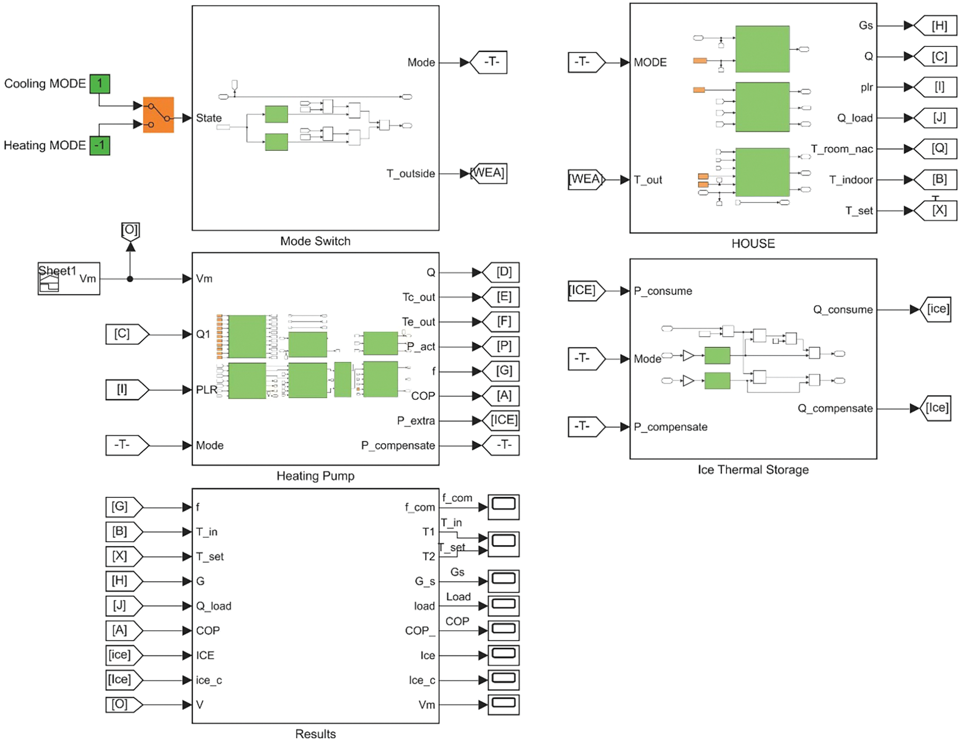
Figure 8: Simulation model in MATLAB & Simulink
4.1 Validation of Simulation Model
In order to validate the simulation model of the DC inverter heat pump, experiments of a real heat pump system were carried out. The cooling capacity of the heat pump was set up as rated value and remained stable, while the DC bus voltage was varied at different stages as shown in Fig. 9. The simulation results and experimental data of effective current, outlet temperature of cooling water and chilling water were compared in Figs. 10 and 11. The average values of differences between the simulation results and the experimental data of effective current, outlet temperature of cooling water and chilling water were 4.4%, 0.2% and 0.02%, respectively, which indicated the models were justifiable.
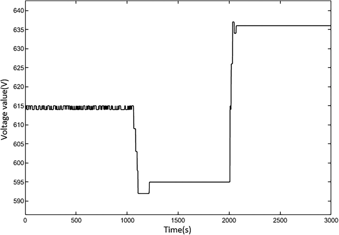
Figure 9: DC bus voltage setting
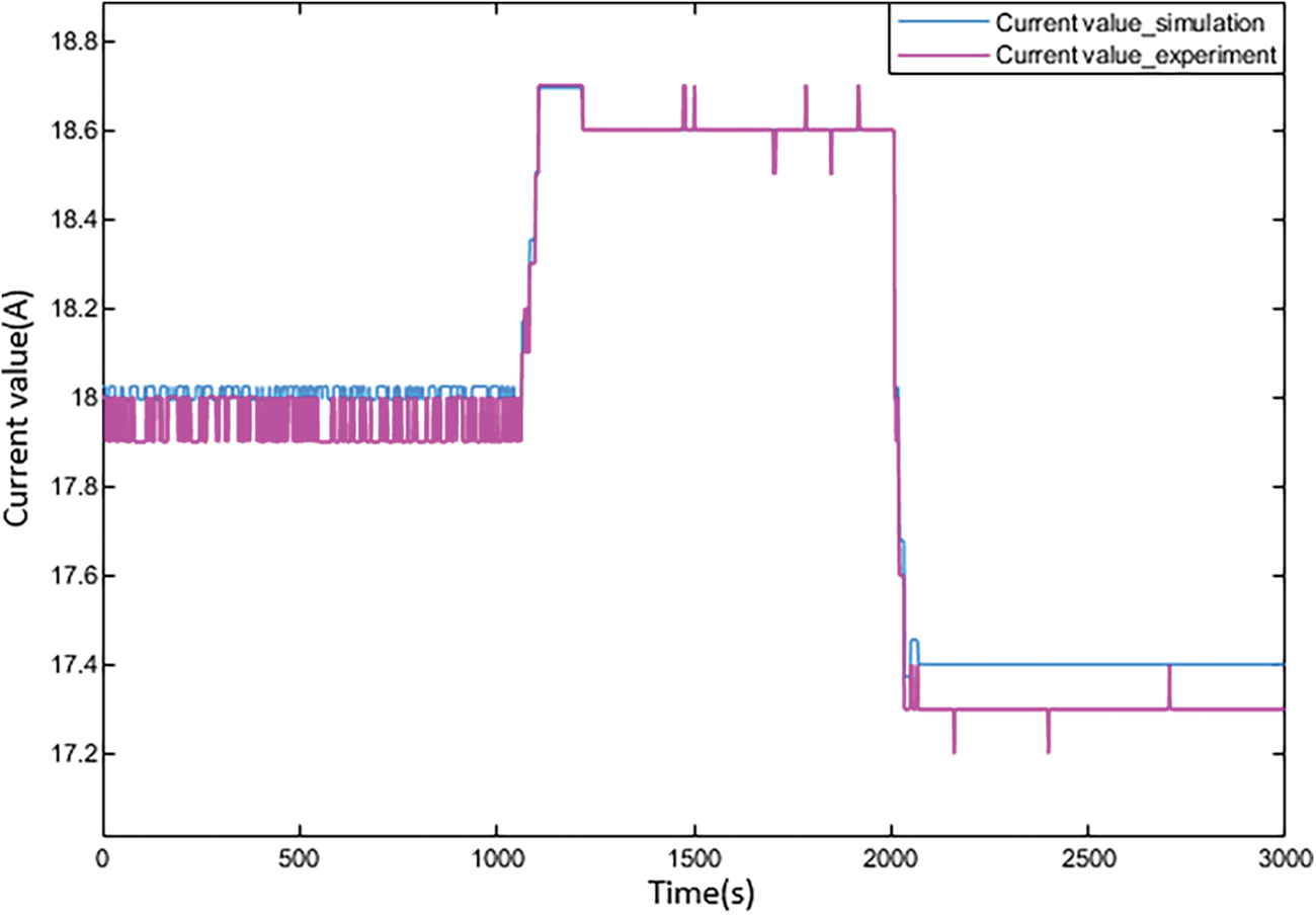
Figure 10: Variation of effective current of the heat pump
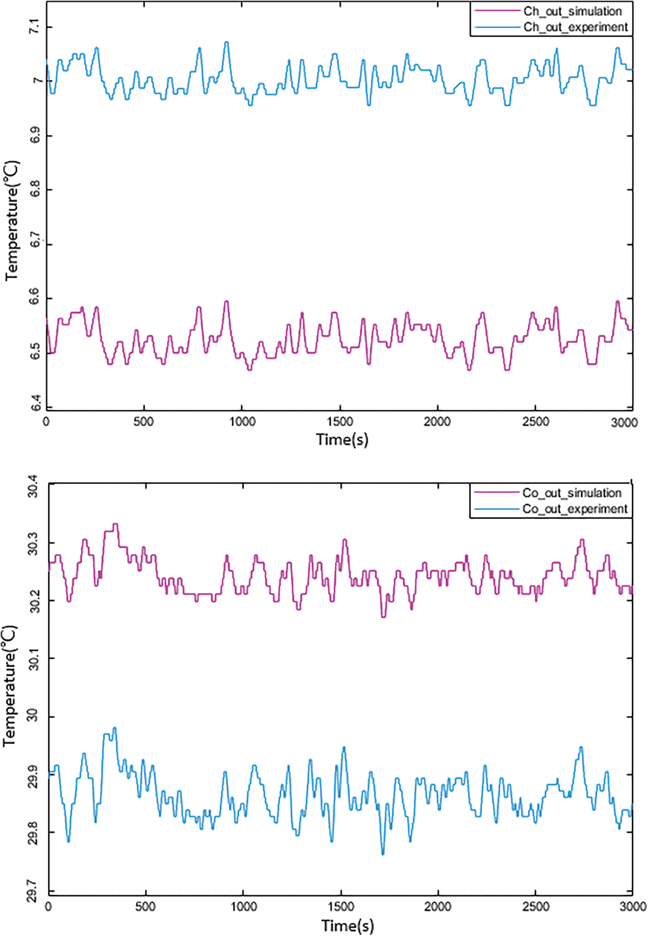
Figure 11: Outlet temperature of cooling water (left) and chilling water (right)
4.2 Analysis of Simulation Results
Table 3 shows the simulation model operating conditions settings, including system refrigeration/heating conditions, simulation time, room control temperature input values, bus voltage range and corresponding compressor operating mode. According to the output of the simulation model of the DC inverter heat pump, the rationale of the control strategy could be explained by analysing the changes in compressor frequency and room temperature corresponding to the change in bus voltage.
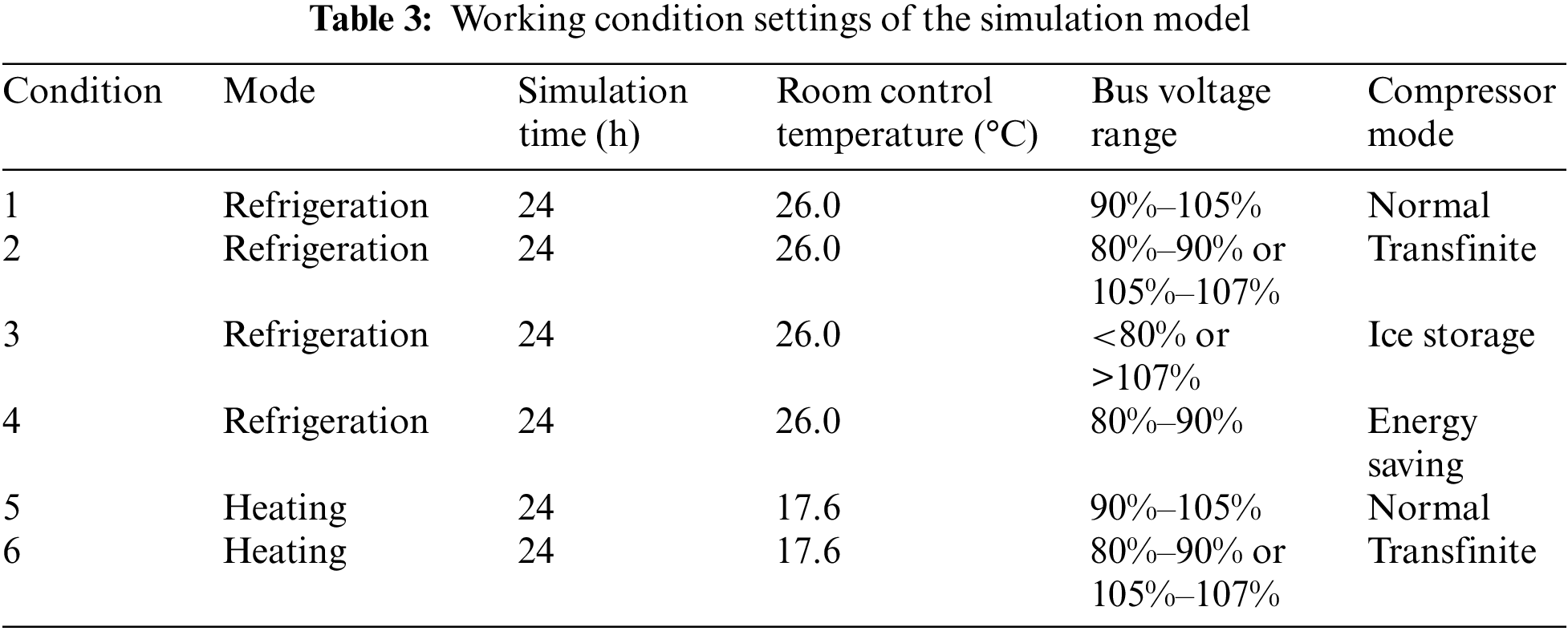
Figs. 12 and 13 show the results of the simulation using condition 1 (refrigeration mode) and condition 2 (refrigeration mode). The settings are presented in Table 3. When the bus voltage was between 80% and 107%, the units functioned normally, in most cases allowing a small range of over the limit operation. However, if the bus voltage fluctuations were too severe, the ice storage module began cooling. As shown in Fig. 12a, the compressor using this control strategy worked normally and the frequency was generally constant when the bus voltage was in the range of 90%–105%. Fig. 13b shows that when the bus voltage was within the range of 80%–90% or 105%–107%, the compressor passively reduced the frequency due to the fluctuation of the bus voltage, the refrigeration capacity decreased, and the maximum frequency of the compressor decreased by 2.7%.
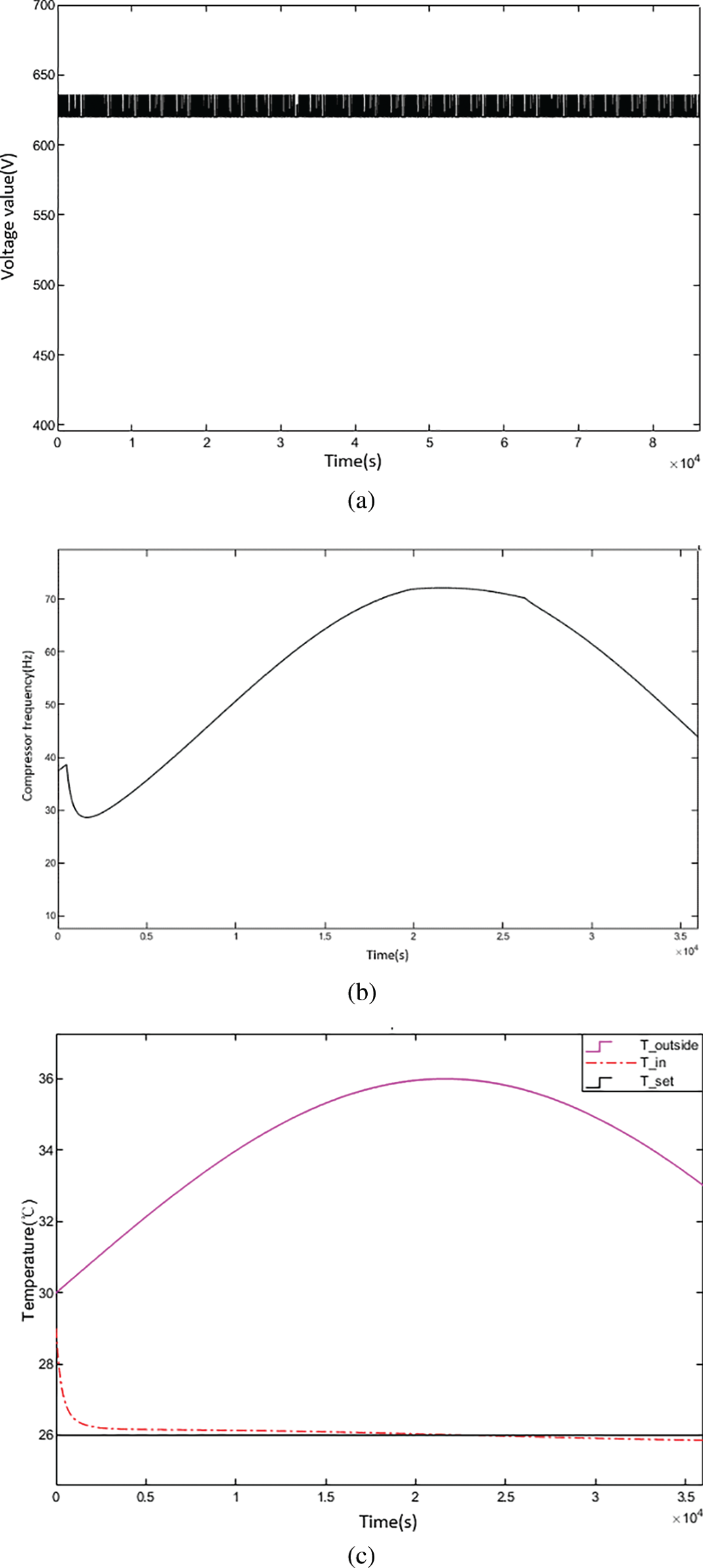
Figure 12: Mode 1 simulation results: (a) Diagram of the bus voltage variation; (b) Diagram of the compressor frequency variation; (c) Diagram of the room temperature change
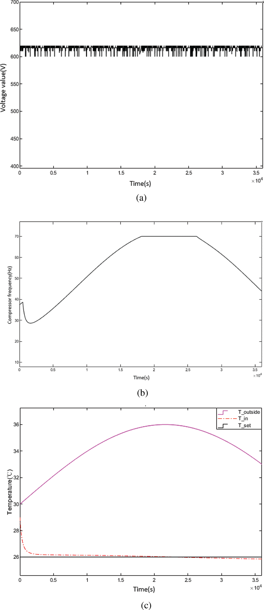
Figure 13: Mode 2 simulation results: (a) Diagram of the bus voltage variation; (b) Diagram of the compressor frequency variation; (c) Diagram of the room temperature change
Fig. 14 shows the results of the simulation using condition 3 (refrigeration mode) using the settings in Table 3, when the bus voltage was less than 80% and more than 107%, and was no longer suitable for long term operation of the heat pump. The results show that the compressor stopped working because the bus voltage was much lower or higher than normal, and the required cooling capacity was provided through the energy storage system.
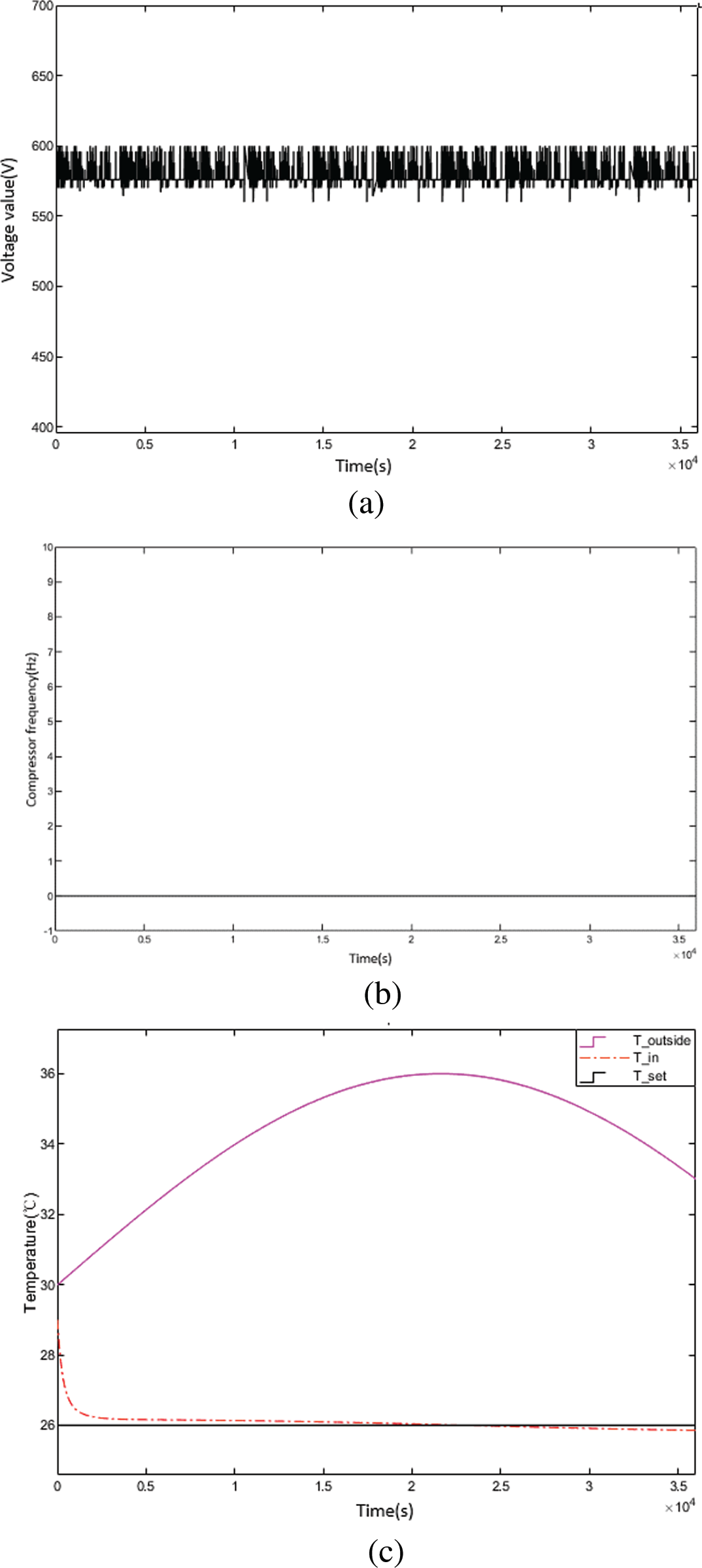
Figure 14: Mode 3 simulation results: (a) Diagram of the bus voltage variation; (b) Diagram of the compressor frequency variation; (c) Diagram of the room temperature change
Fig. 15 shows the results of the simulation using the energy saving mode and operating condition 4 (refrigeration mode), using the settings shown in Table 3. In the energy saving mode, the bus voltage was 80%–90%, which was slightly lower than that of the normal working range of the system. With condition 4 (similar to with condition 2), the instantaneous cooling output of the compressor was reduced by 2.7%, the room temperature was stable, and the ice storage module of the system played its role in transferring the cooling power to the room.
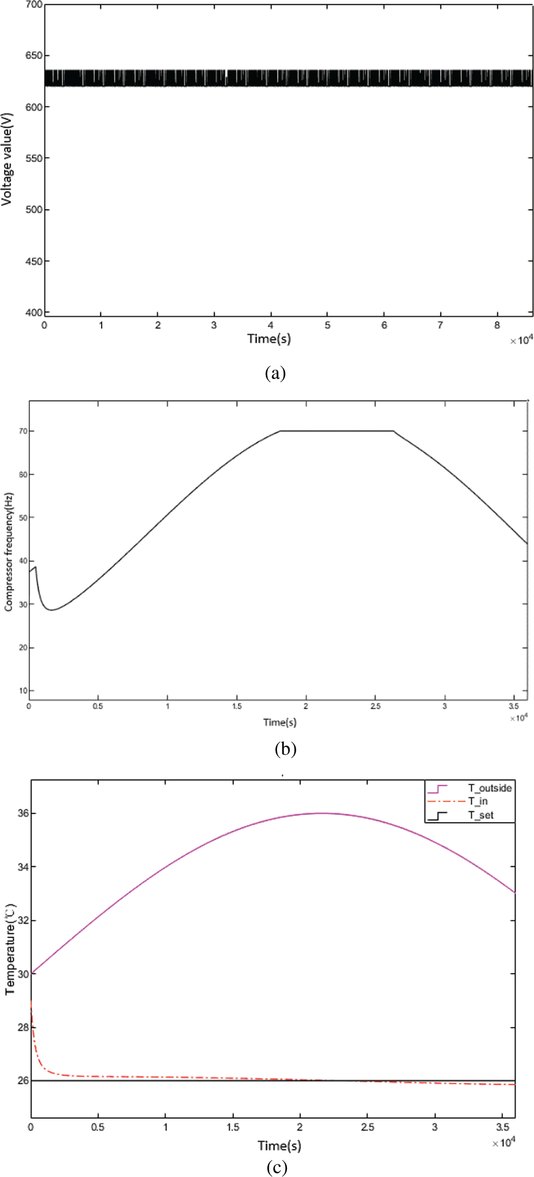
Figure 15: Mode 4 simulation results: (a) Diagram of the bus voltage variation; (b) Diagram of the compressor frequency variation; (c) Diagram of the room temperature change
Figs. 16 and 17 show the results of the simulation using condition 5 (heating mode) and condition 6. The settings are shown in Table 3. When the bus voltage was between 80% and 107%, the system took 30 min to reach the set temperature, after which the unit was able to ensure the stability of the indoor temperature. The maximum compressor frequency decreased by 3.3%. Fig. 17b shows results were the same using conditions 2 and 4.
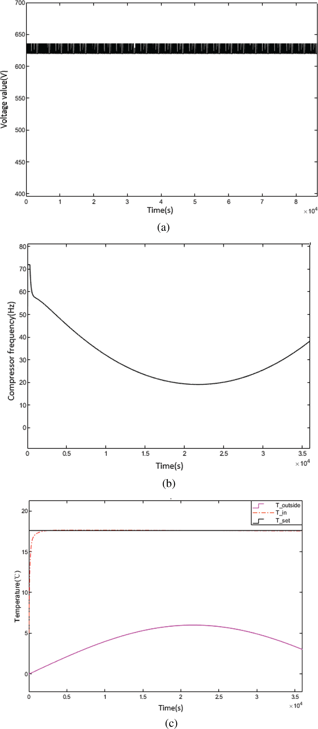
Figure 16: Mode 5 simulation results: (a) Diagram of the bus voltage variation; (b) Diagram of the compressor frequency variation; (c) Diagram of the room temperature change
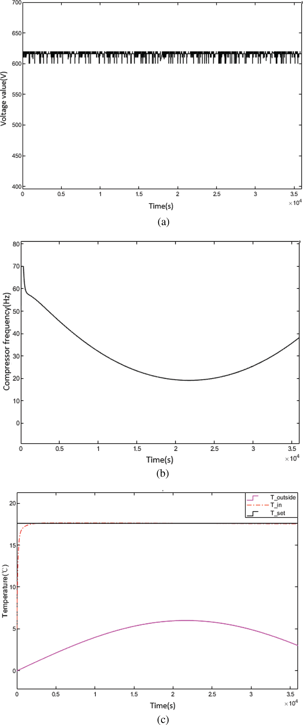
Figure 17: Mode 6 simulation results: (a) Diagram of the bus voltage variation; (b) Diagram of the compressor frequency variation; (c) Diagram of the room temperature change
The fluctuations in frequency and indoor temperature were within a reasonable range. This control strategy completed the indoor load control task under conditions with fluctuating bus voltage, offering stable and energy saving operations when the bus voltage supply was insufficient.
In this paper, a strategy for controlling a DC inverter heat pump system based on a DC network was proposed, including control logic of the compressor, fan, and heat storage system. A simulation model using MATLAB & Simulink was applied to test the rationality of the control logic. The results show that the control strategy proposed in this paper allowed a DC inverter heat pump to operate in a stable manner even with fluctuating input voltage. In both refrigeration and heating conditions, when the bus voltage was in the range of 90%–105%, and the settings were in normal operation mode, the system created a stable and appropriate temperature for the room, the compressor worked normally, and the frequency of the compressor was generally constant; when the bus voltage was in the range of 80%–90% or 105%–107%, the setting was in the small range overrun mode, and the system could still achieve the effect of normal operation. When the compressor occasionally and passively reduced the frequency due to the fluctuation of the bus voltage, the refrigeration capacity decreased to a certain extent, and the overall amplitude of the compressor frequency was reduced. When the bus voltage was less than 80% or greater than 107%, the heat pump stopped working, the compressor working frequency returned to zero, and the ice storage module started working in summer conditions. The operation of the system depends on the capacity of the ice storage module. When the bus voltage was in the range of 80%–90%, the compressor actively reduced the frequency and reduced the instantaneous cooling output, and the unit was in the energy saving operation mode. The results of the simulation showed that the system was able to operate in a stable, energy saving manner.
Building a whole DC supply and distributed energy storage system can fundamentally solve the problem of spikes in an urban power load. This type of system can improve the efficiency of standard power grids and reduce the difficulty inherent in renewable power grids. The DC inverter heat pump system proposed in this study can be extended to become an AC-DC dual-purpose heat pump in the future, which has been more widely used in AC-DC hybrid distribution systems. Nevertheless, the experiments only conducted under rated cooling capacity of the compressor, and the impact of DC bus voltage on the heat pump system was only analysed under recommended values of the specific heat pump unit. Moreover, economic issues such as the electricity bill savings were not considered in this study. In the future, experiments can be expanded to determine the specific operating limits of DC equipment at different powers, and economic aspect of the proposed heat pump system can be also evaluated.
Funding Statement: This research is funded by State Grid Science & Technology Project “Research and Demonstration of Key Technologies on Electric-Heating Collaboration Cross-Network Mutual Supply for Typical Regional Clean Energy”, Grant Number 5400-202111575A-0-5-SF.
Conflicts of Interest: The authors declare that they have no conflicts of interest to report regarding the present study.
References
1. Marszal, A. J., Heiselberg, P., Bourrelle, J. S., Musall, E., Voss, K. et al. (2011). Zero energy building–A review of definitions and calculation methodologies. Energy and Buildings, 43(4), 971–979. https://doi.org/10.1016/j.enbuild.2010.12.022 [Google Scholar] [CrossRef]
2. Khalid, F., Dincer, I., Rosen, M. A. (2016). Techno-economic assessment of a renewable energy based integrated multigeneration system for green buildings. Applied Thermal Engineering, 99(18), 1286–1294. https://doi.org/10.1016/j.applthermaleng.2016.01.055 [Google Scholar] [CrossRef]
3. Efkarpidis, N. A., Vomva, S. A., Christoforidis, G. C., Papagiannis, G. K. (2022). Optimal day-to-day scheduling of multiple energy assets in residential buildings equipped with variable-speed heat pumps. Applied Energy, 312(4), 118702. https://doi.org/10.1016/j.apenergy.2022.118702 [Google Scholar] [CrossRef]
4. Bortolini, M., Gamberi, M., Graziani, A., Manzini, R., Mora, C. (2013). Multi-location model for the estimation of the horizontal daily diffuse fraction of solar radiation in Europe. Energy Conversion and Management, 67, 208–216. https://doi.org/10.1016/j.enconman.2012.11.008 [Google Scholar] [CrossRef]
5. Hurtado, L. A., Rhodes, J. D., Nguyen, P. H., Kamphuis, I. G., Webber, M. E. (2017). Quantifying demand flexibility based on structural thermal storage and comfort management of non-residential buildings: A comparison between hot and cold climate zones. Applied Energy, 195, 1047–1054. https://doi.org/10.1016/j.apenergy.2017.03.004 [Google Scholar] [CrossRef]
6. Jacob, A. S., Banerjee, R., Ghosh, P. C. (2018). Sizing of hybrid energy storage system for a PV based microgrid through design space approach. Applied Energy, 212, 640–653. https://doi.org/10.1016/j.apenergy.2017.12.040 [Google Scholar] [CrossRef]
7. Fischer, D., Bernhardt, J., Madani, H., Wittwer, C. (2017). Comparison of control approaches for variable speed air source heat pumps considering time variable electricity prices and PV. Applied Energy, 204(1), 93–105. https://doi.org/10.1016/j.apenergy.2017.06.110 [Google Scholar] [CrossRef]
8. Pean, T., Costa-Castello, R., Fuentes, E., Salom, J. (2019). Experimental testing of variable speed heat pump control strategies for enhancing energy flexibility in buildings. IEEE Access, 7, 37071–37087. https://doi.org/10.1109/ACCESS.2019.2903084 [Google Scholar] [CrossRef]
9. Mancarella, P. (2014). MES (multi-energy systemsAn overview of concepts and evaluation models. Energy, 65(3), 1–17. https://doi.org/10.1016/j.energy.2013.10.041 [Google Scholar] [CrossRef]
10. Sun, Y., Huang, P., Huang, G. (2015). A multi-criteria system design optimization for net zero energy buildings under uncertainties. Energy and Buildings, 97, 196–204. https://doi.org/10.1016/j.enbuild.2015.04.008 [Google Scholar] [CrossRef]
11. Hu, J., Wu, J., Zhao, C., Wang, P. (2021). Challenges for China to achieve carbon neutrality and carbon peak goals: Beijing case study. PLoS One, 16(11), 258–268. https://doi.org/10.1371/journal.pone.0258691 [Google Scholar] [PubMed] [CrossRef]
12. Shobole, M., Wadi, M., Tür, R., Baysal, M. (2017). Real time active power control in smart grid. IEEE 6th International Conference on Renewable Energy Research and Applications (ICRERA), pp. 585–590. San Diego, USA. [Google Scholar]
13. Fardoun, F., Ibrahim, O., Zoughaib, A. (2011). Quasi-steady state modeling of an air source heat pump water heater. Energy Procedia, 6(1), 325–330. https://doi.org/10.1016/j.egypro.2011.05.037 [Google Scholar] [CrossRef]
14. Zhang, L., Guo, X., Li, W. (2012). Numerical and experimental study on dynamic performance of heat pump water heater with electronic expansion valve. Journal of Energy and Power Engineering, 6(10), 1582–1588. [Google Scholar]
15. Chen, Z., Tao, W., Zhu, Y., Hu, P. (2012). Performance analysis of air water dual source heat pump water heater with heat recovery. Science China Technological Sciences, 42(8), 2148–2156. https://doi.org/10.1007/s11431-012-4905-7 [Google Scholar] [CrossRef]
16. Liu, X., Hao, X., Zhang, D. (2019). The computation on compressor model of DC inverter based on the intelligent sensing algorithm of water heater system performance. Cluster Computing, 22(S3), 5165–5173. https://doi.org/10.1007/s10586-017-1130-y [Google Scholar] [CrossRef]
17. Wang, J., Qv, D., Ni, L., Yao, Y. (2020). Experimental study on an injection-assisted air source heat pump with a novel two-stage variable-speed scroll compressor. Applied Thermal Engineering, 176(1), 115415. https://doi.org/10.1016/j.applthermaleng.2020.115415 [Google Scholar] [CrossRef]
18. Lyu, W., Wang, Z., Li, X., Deng, G., Xu, Z. et al. (2022). Influence of the water tank size and air source heat pump size on the energy saving potential of the energy storage heating system. Journal of Energy Storage, 55, 105542. https://doi.org/10.1016/j.est.2022.105542 [Google Scholar] [CrossRef]
19. Zanetti, E., Scoccia, R., Aprile, M., Motta, M., Mazzarella, L. et al. (2019). Building HVAC retrofitting using a PV assisted DC heat pump coupled with a PCM heat battery and optimal control algorithm. E3S Web of Conferences, vol. 111, pp. 4041–4048. Paris, France, EDP Sciences. [Google Scholar]
20. Roccatello, E., Prada, A., Baggio, P., Baratieri, M. (2022). Analysis of the influence of control strategy and heating loads on the performance of hybrid heat pump systems for residential buildings. Energies, 15(3), 732. https://doi.org/10.3390/en15030732 [Google Scholar] [CrossRef]
21. Ma, J., Fung, A. S., Brands, M., Abul Moyeed, O. M., Mhanna, A. et al. (2021). Effects of photovoltaic/thermal (PV/T) control strategies on the performance of liquid-based PV/T assisted heat pump for space heating. Renewable Energy, 172(4), 753–764. https://doi.org/10.1016/j.renene.2021.02.030 [Google Scholar] [CrossRef]
22. Wang, Z. D., Wen, X. Q., You, L. R., Meng, F. K. (2017). An effective optimized strategy on speed fluctuation suppression for air conditioner compressor. Proceedings of the 36th Chinese Control Conference, pp. 1633–1637. Dalian, China. [Google Scholar]
23. Hajiah, A., Krarti, M. (2012). Optimal control of building storage systems using both ice storage and thermal mass–Part I: Simulation environment. Energy Conversion and Management, 64(1), 499–508. https://doi.org/10.1016/j.enconman.2012.02.016 [Google Scholar] [CrossRef]
24. Hajiah, A., Krarti, M. (2012). Optimal controls of building storage systems using both ice storage and thermal mass–Part II: Parametric analysis. Energy Conversion and Management, 64, 509–515. [Google Scholar]
25. Liao, Y., Huang, G., Sun, Y., Zhang, L. (2014). Uncertainty analysis for chiller sequencing control. Energy and Buildings, 85, 187–198. [Google Scholar]
26. Zhan, B. F., Wang, Z. C., Shao, S. Q. (2022). Simulation investigation on a novel open-loop air cycle heat pump drying system. International Journal of Refrigeration, 141, 31–42. [Google Scholar]
27. Shang, Y., Wu, A., Fang, X., You, Y. (2016). Dynamic simulation of electronic expansion valve controlled refrigeration system under different heat transfer conditions. International Journal of Refrigeration, 72, 41–52. [Google Scholar]
28. Qin, X., Zhang, Y. X. (2022). System development and simulation investigation on a novel compression/ejection transcritical CO2 heat pump system for simultaneous cooling and heating. Energy Conversion and Management, 259, 11579. [Google Scholar]
Cite This Article
 Copyright © 2023 The Author(s). Published by Tech Science Press.
This work is licensed under a Creative Commons Attribution 4.0 International License , which permits unrestricted use, distribution, and reproduction in any medium, provided the original work is properly cited.
 Downloads
 Citation Tools