
 Submit a Paper
 Propose a Special lssue
 Open Access
ARTICLE
Research on ECMS Based on Segmented Path Braking Energy Recovery in a Fuel Cell Vehicle
1 School of Energy and Power Engineering, Shandong University, Jinan, 250061, China
2 Automotive Research Institute, China National Heavy Duty Truck Group Co., Ltd., Jinan, 250061, China
* Corresponding Authors: Ke Sun. Email: ; Shuzhan Bai. Email:
Energy Engineering 2024, 121(1), 95-110. https://doi.org/10.32604/ee.2023.042096
Received 06 June 2023; Accepted 03 August 2023; Issue published 27 December 2023
 View Full Text
 Download PDF
Abstract
Proton exchange membrane fuel cells are widely regarded as having the potential to replace internal combustion engines in vehicles. Since fuel cells cannot recover energy and have a slow dynamic response, they need to be used with different power sources. Developing efficient energy management strategies to achieve excellent fuel economy is the goal of research. This paper proposes an adaptive equivalent fuel minimum consumption strategy (AECMS) to solve the problem of the poor economy of the whole vehicle caused by the wrong selection of equivalent factors (EF) in traditional ECMS. In this method, the kinematics interval is used to update the equivalent factor by considering the penalty term of energy recovery on SOC changes. Finally, the optimized equivalent factor is substituted into the optimization objective function to achieve efficient energy regulation. Simulation results under the New European Driving Cycle show that compared with the traditional ECMS based on fixed SOC benchmarks, the proposed method improves fuel economy by 1.7% while ensuring vehicle power and increases SOC by 30%.Keywords
Nomenclature
| FCHEV | Fuel cell hybrid electric vehicle |
| PEMFC | Proton exchange membrane fuel cells |
| EMS | Energy management system |
| ECMS | Equivalent consumption minimum strategy |
| PMP | Pontrykinson minimum principle |
| EF | Equivalent factor |
| DP | Dynamic programming |
| SOC | Status of charge |
| DC | Direct current |
| Demand of power | |
| Output power of DC/DC | |
| Output power of battery | |
| Efficiency of DC/DC | |
| Output power of fuel cell | |
| Output current of battery | |
| Open circuit voltage of battery | |
| Internal resistance of battery | |
| Output voltage of battery | |
| Capacity of battery | |
| Output voltage of PEMFC | |
| Number of single cells | |
| Reversible voltage | |
| Activation loss | |
| Ohmic loss | |
| Concentration loss | |
| Hydrogen consumption rate | |
| Lower heating value of hydrogen | |
| Efficiency of PEMFC | |
| Motor power | |
| Motor torque | |
| Motor speed | |
| Efficiency of motor | |
| Equivalent hydrogen consumption rate | |
| Equivalent hydrogen consumption rate of battery | |
| Equivalent factor of discharge | |
| Equivalent factor of charge | |
| Efficiency of discharge | |
| Efficiency of charge | |
| Regenerative power of motor | |
| Regenerative energy |
Traditional gasoline and diesel engines have led to many problems, such as global warming, environmental pollution, and waste of fossil fuels [1]. As a clean fuel that is widely recognized worldwide, hydrogen energy can effectively reduce greenhouse gases and global warming caused by the burning of fossil fuels [2]. Fuel cells are power generation devices that directly convert the chemical energy in fuel into electrical energy through electrochemical reactions. They were first used in special fields such as aviation, aerospace, diving, and military. Conventional internal combustion engines are limited by the Carnot cycle and have an energy utilization rate of only about 35%. The energy conversion efficiency of fuel cells can reach more than 50%. If waste heat recovery technology is adopted, the total energy utilization rate of fuel cells can reach 80% [3].
Despite the advantages of PEM fuel cells, their low dynamic response cannot meet the rapid power changes of vehicles in real time. Frequent power changes can accelerate the aging of fuel cells and affect their service life. Therefore, ancillary devices such as batteries are used to complement this feature to the vehicle’s transient response [4]. In order to coordinate the power distribution of vehicles with multiple power sources, a rational EMS is required [5]. Current EMSs are classified into two types: rule-based energy management strategies and optimization-based energy management strategies [6]. The rule-based energy management strategy is based on the experience of engineers or experts to design some simple rules to guide the energy distribution of the hybrid system [7,8]. The execution of deterministic rule-based strategies is relatively simple and requires low computing power for on-board processors. With these advantages, this strategy has become the most common energy management strategy for fuel cell hybrid electric vehicles. Power tracking and its improved strategies have been successfully applied to models such as Toyota Mirai [8] and Honda Clarity. Common rule-based strategies include deterministic rules and fuzzy rules [9,10]. Fares et al. designed the PID controller algorithm, which reduces hydrogen fuel consumption by 30% and system cost consumption by more than 10% under the FUDS driving cycle compared to the state control algorithm. Fuzzy logic rules, as a type of deterministic rules, use an imprecise system model where the states are represented by different affiliation functions [11]. Zhang et al. [12] proposed a fuzzy controller and low-pass filter to extend FC lifetime and reduce hydrogen consumption. Simulation results from highway fuel economy certification tests, urban dynamometer driving schedules and the new European driving cycle show that the proposed approach smoothes the fuel cell output and performs in real-time, resulting in a 19% reduction in current variation but an increase in hydrogen consumption of about 10%.
Optimization-based energy management strategies have received a lot of attention in recent years. This strategy usually establishes a cost function with fuel consumption or component durability as the optimization objective. The steps to solve the problem are: construct the optimization problem, establish the optimization objective function, consider the parameter constraints, and finally solve the solution that satisfies the optimization objective function. The DP algorithm is an optimization method that transforms a multi-stage process into a series of single-stage problems, utilizing the relationships between each stage to solve them one by one. The global optimal energy management strategy based on dynamic programming developed by Xu et al. [13] reduces the computation time by optimizing the coefficients of the dynamic programming algorithm and finds the optimal solution for the battery and fuel cell configuration under typical cycles of Chinese urban buses. Sun et al. obtained the optimal energy distribution using the PMP, which reduced hydrogen consumption by an average of 20.3% and 28.9% through simulation and experimentation compared to rule-based energy management strategies. However, these algorithms require the entire driving cycle information to be known in advance as a priori knowledge, making the algorithm impossible to apply in the real process [14].
The ECMS method is a typical example of a local optimization strategy. It incorporates the electricity in the batteries into the fuel consumption to ensure the minimum fuel consumption of the total power source, i.e., to calculate the instantaneous equivalent consumption; in addition, the algorithm is computationally small and has good real-time performance. However, the value of EF is optimized based on the vehicle’s operating conditions and performance requirements [15,16]. It directly affects the fuel consumption and performance of vehicles. Current ECMS-based studies have focused on the construction of equivalence factors. Han et al. [17] proposed a method to extract the global optimal EF trajectory from DP. The method is applied to the design of EF adaptive strategy and investigated for hilly road sections. The results show that the optimal EF significantly improves the fuel economy under hilly road sections. Han et al. [18] proposed a real-time update method for the ECMS equivalence factor based on the operating mode of the motor. The results show that the algorithm can improve fuel economy and fuel cell lifetime at different test cycles.
However, most of the previous studies on the penalty function are based on a fixed SOC reference, which leads to unnecessary fuel economy loss due to excessive penalty at some moment points [19–22]. In this paper, to this end, a fuel cell hybrid semi-trailer is used as a prototype, and a variable SOC-referenced ECMS energy management strategy based on road spectrum segmentation is proposed in the paper. By dynamically adjusting the SOC reference value of the penalty function, the same result as that of the fixed SOC-referenced ECMS can be achieved in maintaining the balance of the power supply, and at the same time the optimum value of the battery charging and discharging torque can be retained to the maximum extent, so that fuel consumption can be avoided from increasing by too much penalization. The fuel consumption increase caused by excessive penalties is avoided. Recording starts from the time when the vehicle speed is zero and is recorded as a segment when the vehicle speed is zero again. By segmenting the operating road conditions, the SOC reference value of the penalty function is dynamically adjusted so that the battery can give full play to the function of assisting fuel cell operation and braking energy recovery. At the same time, the optimal value of battery charging and discharging power is retained to the maximum extent to avoid the increase in fuel consumption caused by excessive penalties.
The main contents of the article are as follows, the second part is the introduction of the system structure and model, and the third part is the proposal of the adaptive ECMS method. The fourth part is the discussion and conclusion, this part presents the simulation results and discussion, and the fifth part is the conclusion.
In this section, the fuel cell hybrid vehicle is modeled. In order to satisfy the realism of the simulation, we also conducted experimental verification. The fuel cell hybrid electric truck studied in this paper mainly consists of a fuel cell, a battery, a unidirectional DC/DC converter, a drive motor, and a vehicle controller, as shown in Fig. 1. The fuel cell is connected in parallel with the battery through the unidirectional DC/DC controller to form a composite energy system. The fuel cell consists of auxiliary devices such as an air compressor, condenser, humidifier, pressure-reducing valve, and fuel cell stack cooling system. The battery pack is a power pack consisting of multiple individual cells [23].
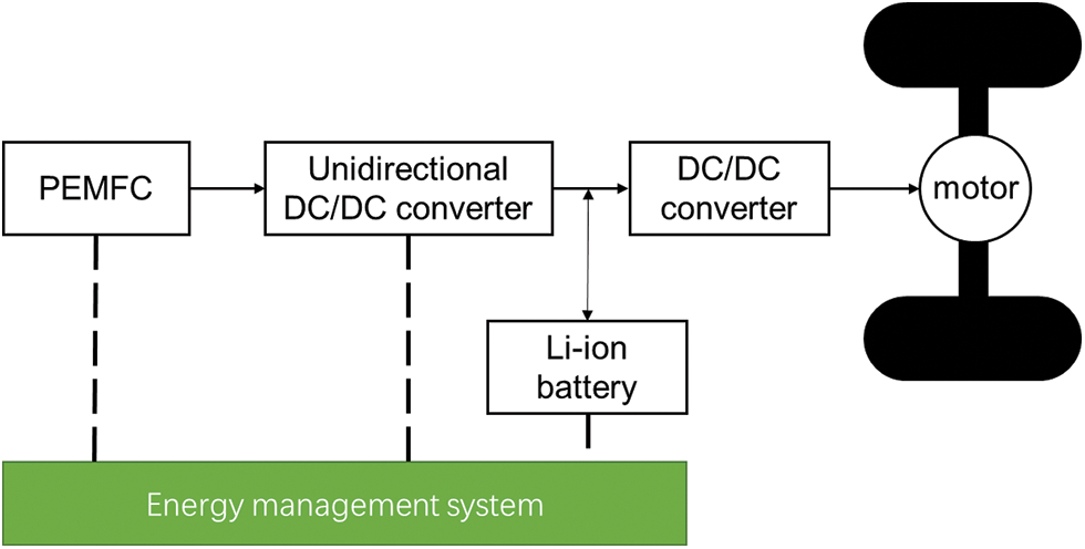
Figure 1: The FCHEVs configuration
The primary source of vehicle power is the hydrogen-oxygen electrochemical reaction that occurs in the hydrogen fuel cell, which converts chemical energy into electrical energy. The other part of the vehicle’s power supply is the power battery. Compared to other vehicle configurations, this topology eliminates the DC/DC converter between the battery and the DC bus, improving energy conversion efficiency and space utilization [24].
2.1 Longitudinal Dynamics Model
The demand power of the fuel cell vehicle is composed of two parts, which are the fuel cell DC/DC output power and the battery output power, and the specific formula is as follows:
Although the
As the second energy source of fuel cell hybrid electric vehicles, the battery is a very important component in the vehicle system. The battery can convert chemical energy and electrical energy into each other, representing a reversible electrical energy storage system. The
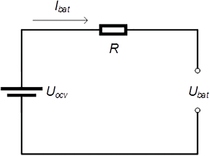
Figure 2: Internal resistance equivalent model of battery
As the main power source of fuel cell hybrid vehicles, the proton exchange membrane fuel cell converts chemical energy into electrical energy through the hydrogen-oxygen reaction. Due to the extremely complex internal structure of the fuel cell, building a complete FCS model would result in a long computational time. Therefore, the FCS model used in this study is a simplified model. The output voltage of the fuel cell is as follows [25]:
In order to minimize the hydrogen consumption of the fuel cell, the fuel cell stack should operate in the high-efficiency region. The theoretical efficiency of a fuel cell is defined as the ratio between the power produced and the hydrogen power. The hydrogen consumption of the fuel cell is calculated from these two parameters by Eq. (9).
The polarization curve of the fuel cell used in this article is shown in Fig. 3.
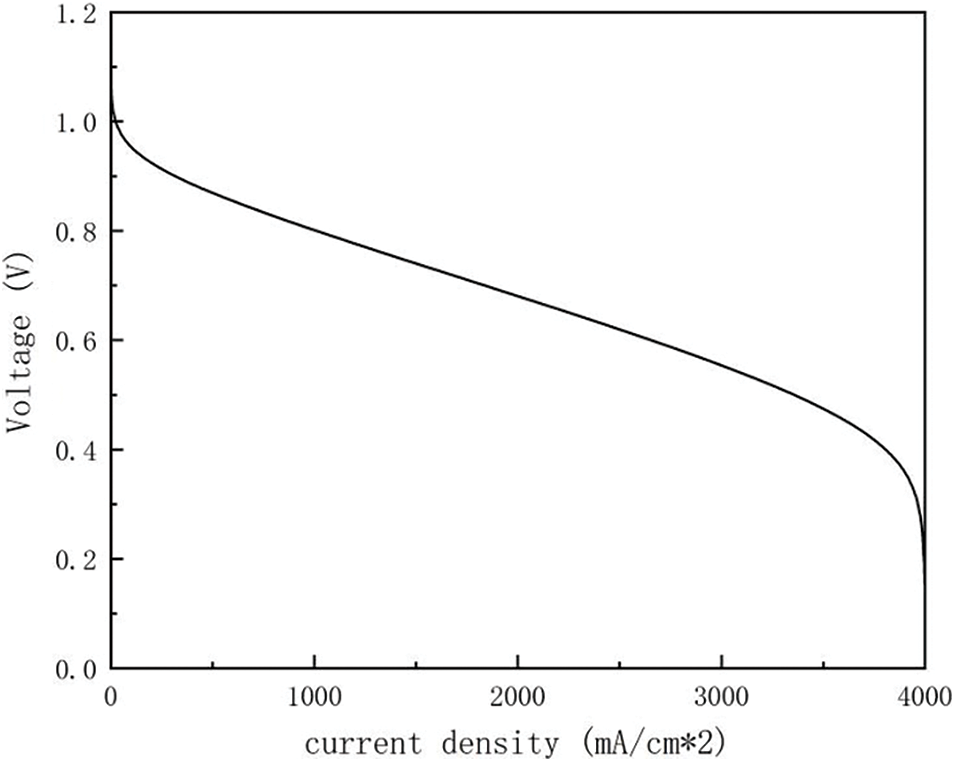
Figure 3: Fuel cell polarization curves
The motor can operate in generator mode or tractor mode alternatively. When operating as a tractor, it provides drive power to the vehicle. When operating as a generator, it recovers the vehicle’s braking energy and provides braking torque. The model can be represented as follows:
The vehicle model was validated by a real drive cycle simulation. Fig. 4 illustrates that the vehicle velocity follows closely with the demanded velocity.
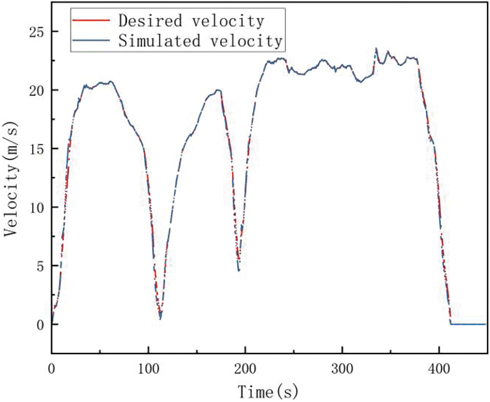
Figure 4: Vehicle model validation
3 ECMS Model for Variable SOC Reference
In this section, three ECMS methods are described in detail, namely conventional ECMS, ECMS based on fixed SOC reference and ECMS based on segmented brake energy recovery.
3.1 ECMS and ECMS Model for Fixed SOC Reference
Fuel cells require timely charging and discharging of batteries to work together due to poor dynamic response. Fully utilizing the power recovery capability and power output capability of the battery is an effective means of improving fuel economy. Therefore, the reasonable allocation of power between two power sources can be regarded as a general optimal control problem.
The energy consumption in ECMS consists of two parts, namely the amount of hydrogen consumed by fuel cells and the equivalent amount of hydrogen consumed by batteries. The objective function for a traditional ECMS (ECMS1) is shown in Eq. (11).
The actual hydrogen consumption of the fuel cell is shown in Eq. (12).
The conversion relationship between the fuel cell and hydrogen consumption is shown in Eq. (13).
Since the traditional ECMS is unable to maintain the balance of SOC, an ECMS strategy based on SOC feedback (ECMS2) has emerged. The centerpiece of this strategy is the correction of the EF based on the deviation of the SOC from the initial SOC. The corrected battery equivalent fuel consumption rate is as follows:
Under certain operating conditions, the control strategy with fixed SOC will fail to achieve the optimal control effect due to the irrational selection of the equivalence factor. In the following, the effect of the SOC penalty function on fuel economy is investigated when the battery output power is positive.
Define the larger discharge moment as follows: Let the battery demand power at time
The
In ECMS2, due to the large tendency of discharge, the penalty function
The SOC of the battery is as follows.
At this point,
The energy released by the battery less is Eq. (21).
If
Through the above analysis, we know that: at the moment when the battery tends to a larger discharge, the penalty coefficient of the fixed SOC as the reference control strategy is too large, which will lead to the system not being able to obtain the optimal value, and it is necessary to adjust the penalty coefficient in time.
For this reason, the kinematic interval concept in the driving condition construction theory is introduced in the paper. The kinematic interval is defined as the interval from one stop to the next, and Fig. 5 shows the kinematic interval.
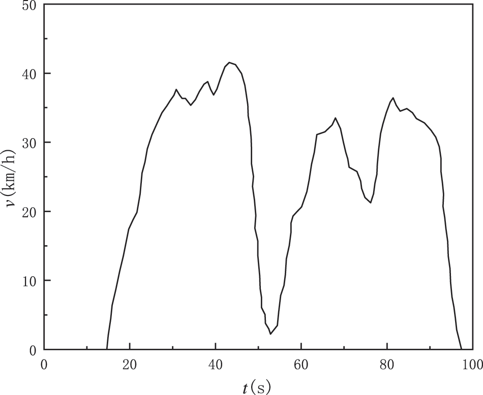
Figure 5: Schematic diagram of kinematics fragment
With known operating conditions, the driving conditions are divided into a number of motion intervals and the braking recovery energy within each interval is calculated. The initial battery capacity is subtracted from the braking recovery energy, and the
Based on the above analysis, the algorithm steps of the ECMS control strategy (ECMS3) based on variable SOC reference are as follows:
Step 1: The driving condition is divided into m kinematics intervals, and the braking recovery energy of the i-th interval is calculated by the above three Eqs. (22)–(24), and the corresponding
Step 2: Run the driving condition, in the i-th kinematic interval, first calculate the optimal value without
Step 3: If
Step 4: Repeat Steps 2 and 3 until the end of the driving condition.
The calculation process of the ECMS model based on variable SOC reference is shown in Fig. 6. Through the above process, the dynamic equations of the ECMS model based on variable SOC reference for energy recovery can be obtained as follows:
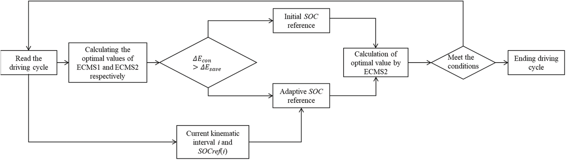
Figure 6: Simulation process of ECMS with variable SOC reference
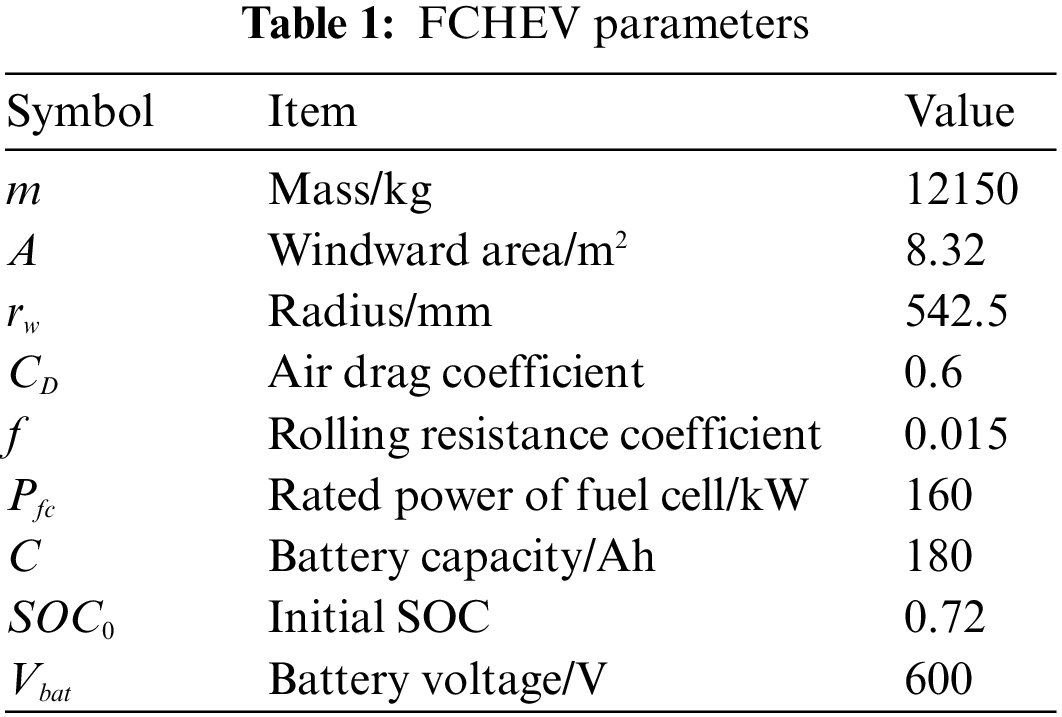
To verify the effectiveness of the proposed method, the hybrid system parameters shown in Table 1 were selected for modeling and simulation.
The model shown in Fig. 7 was built in Matlab/Simulink and simulated with the new European cycle condition (NEDC) (shown in Fig. 8) as the test condition.
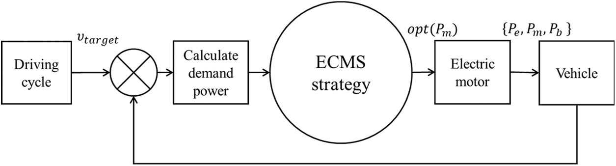
Figure 7: Simulation structure of hybrid power system
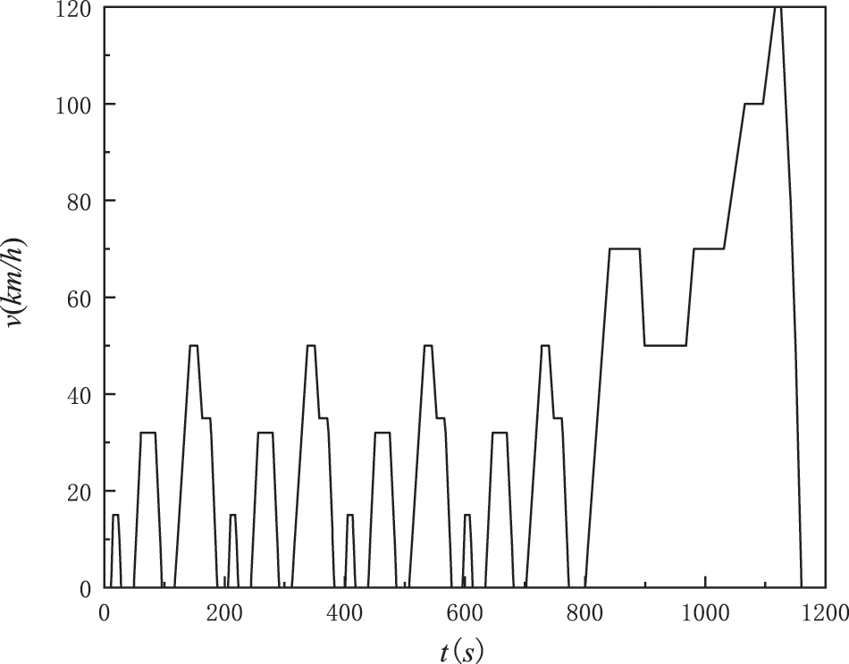
Figure 8: Standard NEDC driving cycle
The penalty function in ECMS2 is as follows:
where
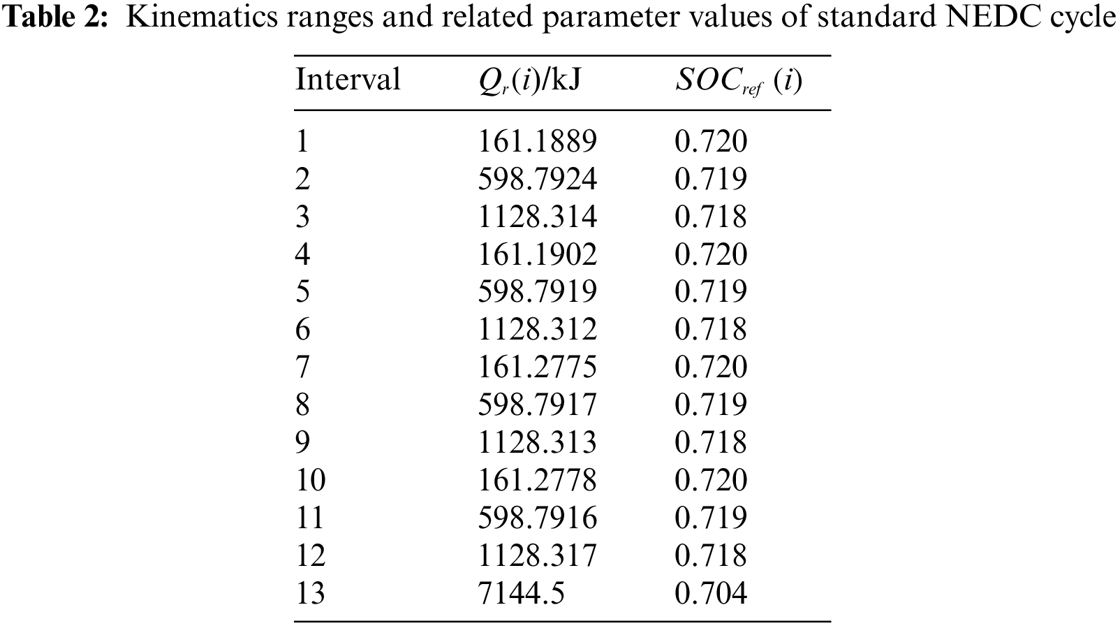
According to the kinematics interval definition, NEDC can be divided into 13 kinematics intervals, of which 1–12 have only one deceleration section and interval 13 has two deceleration sections. The braking recovery energy and the corresponding SOC reference value for each interval are calculated according to Eqs. (21)–(23), as shown in Table 2.
In order to facilitate comparative analysis, the variation of battery SOC obtained from ECMS1, ECMS2 and ECMS3 is given (as shown in Fig. 9), as well as the battery power output status and fuel cell output status of the 3 different strategies during the whole cycle, and the optimal equivalent energy consumption for the whole driving cycle is shown in the following Table 3.
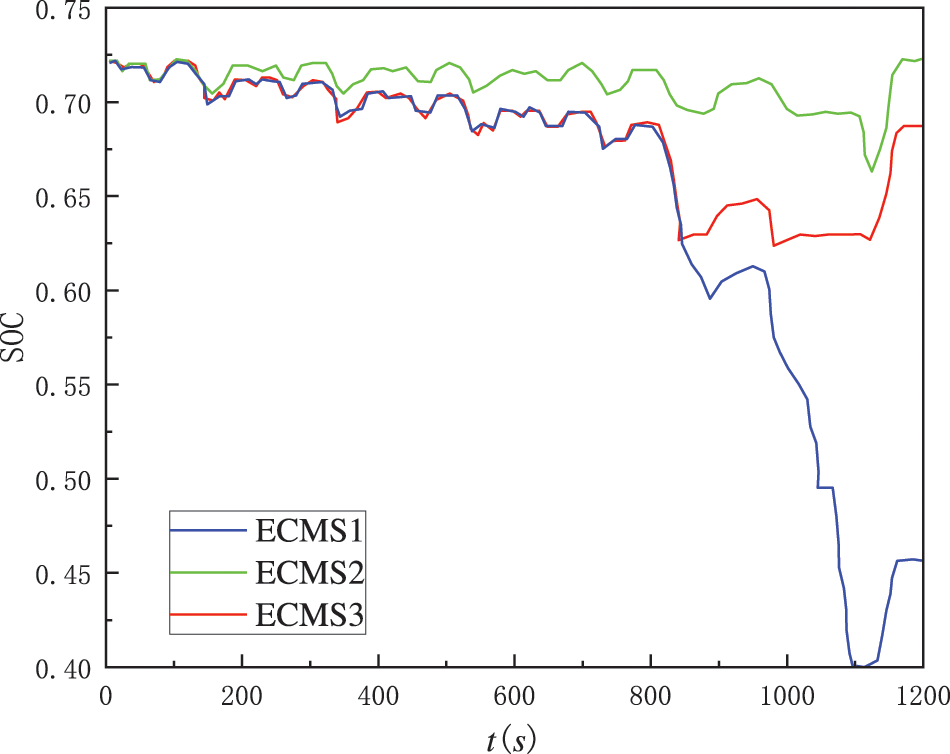
Figure 9: SOC curves of different ECMS models
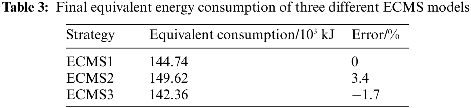
Since this paper focuses on the effect of the SOC-based penalty function on the arithmetic results, it is necessary to use the results obtained by ECMS1 as a reference to illustrate the problem. Since the SOC range in the control strategy is defined as 0.4–0.9, it can be seen from Fig. 7 that the SOC of the ECMS1 strategy, even with the largest discharge, remains within this range. In this case, the final SOC of ECMS1 is 0.46 with a deviation from the initial SOC value of 0.72 of 36.1%, which is the highest among the three strategies. The final SOC deviation of ECMS2 is 2.1%, which is the lowest among the three strategies. The final SOC of ECMS3 is 0.69, with a deviation of 4.2%, which is very close to the ECMS2 strategy and can meet the power preservation ECMS strategy’s basic requirements. Combined with the equivalent energy consumption shown in Table 3, the ECMS3 strategy consumes 2380 kJ less than ECMS1, with a reduction rate of 1.7%. The ECMS2 consumes 4880 kJ less than ECMS1, with an increase rate of 3.4%. Therefore, the equivalent energy consumption of ECMS3 is 7260 kJ less than that of ECMS2.
Several phenomena in Fig. 9 can be further analyzed in conjunction with Figs. 10 and 11.
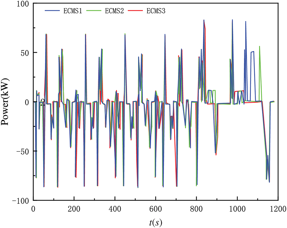
Figure 10: Best output power of battery under different ECMS strategy
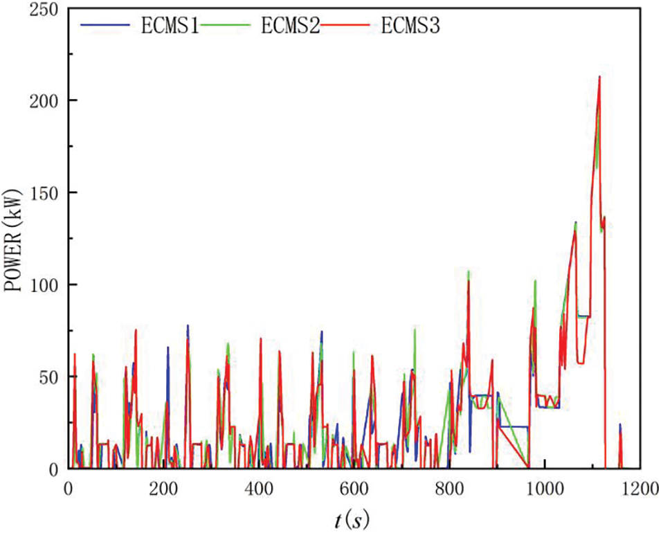
Figure 11: Best output power of battery under different ECMS strategy
(1) The results of the ECMS1 strategy show that the battery can increase the output power when the vehicle needs high power, while the effect of ECMS2 and ECMS3 is not obvious. the reason for the obvious effect of ECMS1 is that, because there is no SOC feedback, when the battery tends to output high power, the control strategy only considers the minimum SOC limit, so that the battery continues to discharge and the power battery can output high power to assist the fuel cell. The reason for the insignificant effect of ECMS2 and ECMS3 is that, firstly, ECMS2 and ECMS3 can have more significant battery power output like ECMS1 strategy before 800 s when the vehicle power demand is high. After 800 s, the battery power output of ECMS2 and ECMS3 cannot follow the battery power output of ECMS1 and the driving effect is not obvious. In the simulation, it is found that the equivalent fuel consumption is highly sensitive to the equivalence factor, and a small change in the equivalence factor leads to different strategy selection results. Since ECMS2 and ECMS3 have SOC feedback, the final expression is in the form of changing the magnitude of the equivalence factor. In the first 800 s, the power output of ECMS1 can be essentially tracked because the SOC has little penalty due to the small difference from the initial value. In kinematic interval 13, the actual SOC of ECMS2 and ECMS3 is very different from the initial SOC (especially the ECMS3 strategy), so the penalty is very large. When the power output of the battery becomes larger, the penalty to the battery discharge increases and the calculated equivalent fuel consumption will be larger. At this point, the maximum output power of the fuel cell itself can meet the dynamic demand, resulting in the output power of the battery being determined by the control strategy.
(2) Compared to ECMS2, ECMS3 can track the battery power output of ECMS1 for most of the entire cycle. Since the penalty function in ECMS2 is based on a fixed SOC reference, the penalty increases linearly as the SOC deviates from the initial SOC, limiting the battery power output and resulting in a smaller range of SOC variation. In ECMS3, the SOC reference value can be reduced in time for each kinematic range, which makes the penalty function less severe for the first 900 s. The actual output power of the battery can track the output power of ECMS1, and the discharge capacity of the battery increases, leading to a rapid decrease in the actual SOC. Meanwhile, in the 900–1100 s cycle, the penalty increases significantly due to the large difference between the actual SOC and the initial SOC, and the equivalent fuel consumption is more sensitive to the equivalence factor, which limits the battery power output to a certain extent and ensures that the SOC does not drop further, thus maintaining the power balance.
In an ECMS strategy with SOC feedback, the penalty function based on a fixed SOC reference tends to increase fuel consumption due to excessive penalty when the power battery tends to be heavily discharged. To address this problem, this paper proposes a method to continuously adjust the SOC reference value using braking energy recovery during the motion interval to control the penalty intensity and improve fuel economy. The standard driving cycle NEDC simulation results show that when the initial SOC of the battery is 0.72, the proposed method can reach 0.69 with a deviation of only 4.2%, which can meet the basic requirements of electric power maintenance. Compared with the ECMS strategy based on a fixed SOC benchmark, it reduces 7260 kJ equivalent energy consumption, which improves the fuel economy to a certain extent.
Acknowledgement: The author acknowledges the support of China National Heavy Duty Truck Research Institute.
Funding Statement: This work was supported by National Key R&D Program of China (Grant No. 2020YFB0106603), the Key Research and Development Program of Shandong Province (Grant No. 2020CXGC010406) and the Key Research and Development Program of Shandong Province (Grant No. 2019JZZY010912).
Author Contributions: The authors confirm contribution to the paper as follows: study conception and design: Shuzhan Bai, Ke Sun; data collection: Wen Sun, Meijing Li; analysis and interpretation of results: Wen Sun, Meijing Li, Guoxiang Li; draft manuscript preparation: Wen Sun. All authors reviewed the results and approved the final version of the manuscript.
Availability of Data and Materials: The data and materials used in this study are available upon request. Interested parties can contact the lead author, Dr. Wen Sun, at sunwensdu@foxmail.com to obtain access to the data and materials.
Conflicts of Interest: The authors declare that they have no conflicts of interest to report regarding the present study.
References
1. Teng, T., Zhang, X., Dong, H., Xue, Q. C. (2020). A comprehensive review of energy management optimization strategies for fuel cell passenger vehicle. International Journal of Hydrogen Energy, 45(39), 20293–20303. [Google Scholar]
2. İnci, M., Büyük, M., Demir, M. H., İlbey, G. (2021). A review and research on fuel cell electric vehicles: Topologies, power electronic converters, energy management methods, technical challenges, marketing and future aspects. Renewable and Sustainable Energy Reviews, 137(12), 110648. [Google Scholar]
3. Sulaiman, N., Hannan, M. A., Mohamed, A., Majlan, E. H., Wan Daud, W. R. (2015). A review on energy management system for fuel cell hybrid electric vehicle: Issues and challenges. Renewable and Sustainable Energy Reviews, 52(6), 802–814. [Google Scholar]
4. Ansarey, M., Shariat Panahi, M., Ziarati, H., Mahjoob, M. (2014). Optimal energy management in a dual-storage fuel-cell hybrid vehicle using multi-dimensional dynamic programming. Journal of Power Sources, 250(2), 359–371. [Google Scholar]
5. Hou, S. Y., Gao, J. W. F., Zhang, Y., Chen, M., Shi, J. P. et al. (2020). A comparison study of battery size optimization and an energy management strategy for FCHEVs based on dynamic programming and convex programming. International Journal of Hydrogen Energy, 45(41), 21858–21872. [Google Scholar]
6. Zhao, X. L., Wang, L., Zhou, Y. L., Pan, B. X., Wang, R. C. et al. (2022). Energy management strategies for fuel cell hybrid electric vehicles: Classification, comparison, and outlook. Energy Conversion and Management, 270(30), 116179. [Google Scholar]
7. Gao, D. W., Jin, Z. H., Lu, Q. C. (2008). Energy management strategy based on fuzzy logic for a fuel cell hybrid bus. Journal of Power Sources, 185(1), 311–317. [Google Scholar]
8. Pielecha, I., Cieślik, W., Szałek, A. (2018). The use of electric drive in urban driving conditions using a hydrogen powered vehicle–Toyota Mirai. Combustion Engines, 172(1), 51–58. [Google Scholar]
9. Sulaiman, N., Hannan, M. A., Mohamed, A., Ker, P. J., Majlan, E. H. et al. (2018). Optimization of energy management system for fuel-cell hybrid electric vehicles: Issues and recommendations. Applied Energy, 228(2), 2061–2079. [Google Scholar]
10. Tran, D. D., Vafaeipour, M., El Baghdadi, M., Barrero, R., van Mierlo, J. et al. (2020). Thorough state-of-the-art analysis of electric and hybrid vehicle powertrains: Topologies and integrated energy management strategies. Renewable and Sustainable Energy Reviews, 119(80), 109596. [Google Scholar]
11. Fares, D., Chedid, R., Karaki, S., Jabr, R., Panik, F. et al. (2014). Optimal power allocation for a FCHV based on linear programming and PID controller. International Journal of Hydrogen Energy, 39(36), 21724–21738. [Google Scholar]
12. Zhang, R. D., Tao, J. L. (2018). GA-based fuzzy energy management system for FC/SC-powered HEV considering H2 consumption and load variation. IEEE Transactions on Fuzzy Systems, 26(4), 1833–1843. [Google Scholar]
13. Xu, L. F., Mueller, C. D., Li, J. Q., Ouyang, M. G., Hu, Z. Y. (2015). Multi-objective component sizing based on optimal energy management strategy of fuel cell electric vehicles. Applied Energy, 157(10), 664–674. [Google Scholar]
14. Sun, X. X., Zhou, Y. F., Huang, L. J., Lian, J. (2021). A real-time PMP energy management strategy for fuel cell hybrid buses based on driving segment feature recognition. International Journal of Hydrogen Energy, 46(80), 39983–40000. [Google Scholar]
15. Vignesh, R., Ashok, B. (2023). Intelligent energy management through neuro-fuzzy based adaptive ECMS approach for an optimal battery utilization in plugin parallel hybrid electric vehicle. Energy Conversion and Management, 280(2), 116792. [Google Scholar]
16. Rezaei, A., Burl, J. B., Zhou, B. (2018). Estimation of the ECMS equivalent factor bounds for hybrid electric vehicles. IEEE Transactions on Control Systems Technology, 26(6), 2198–2205. [Google Scholar]
17. Han, J. H., Park, Y. J., Kum, D. S. (2014). Optimal adaptation of equivalent factor of equivalent consumption minimization strategy for fuel cell hybrid electric vehicles under active state inequality constraints. Journal of Power Sources, 267(2), 491–502. [Google Scholar]
18. Han, J. H., Park, Y. J. (2012). A novel updating method of equivalent factor in ECMS for prolonging the lifetime of battery in fuel cell hybrid electric vehicle. IFAC Proceedings Volumes, 45(30), 227–232. [Google Scholar]
19. Yin, L. Z., Li, Q., Wang, T. H., Liu, L., Chen, W. R. (2019). Real-time thermal management of open-cathode PEMFC system based on maximum efficiency control strategy. Asian Journal of Control, 21(4), 1796–1810. [Google Scholar]
20. Wang, Y. Q., Moura, S. J., Advani, S. G., Prasad, A. K. (2019). Power management system for a fuel cell/battery hybrid vehicle incorporating fuel cell and battery degradation. International Journal of Hydrogen Energy, 44(16), 8479–8492. [Google Scholar]
21. Gao, H. Z., Wang, Z. J., Yin, S. P., Lu, J., Guo, Z. Y. et al. (2021). Adaptive real-time optimal energy management strategy based on equivalent factors optimization for hybrid fuel cell system. International Journal of Hydrogen Energy, 46(5), 4329–4338. [Google Scholar]
22. Tian, X., Cai, Y. F., Sun, X. D., Zhu, Z., Xu, Y. Q. (2019). An adaptive ECMS with driving style recognition for energy optimization of parallel hybrid electric buses. Energy, 189(12), 116151. [Google Scholar]
23. Li, H., Ravey, A., N’Diaye, A., Djerdir, A. (2018). A novel equivalent consumption minimization strategy for hybrid electric vehicle powered by fuel cell, battery and supercapacitor. Journal of Power Sources, 395(6), 262–270. [Google Scholar]
24. Zhang, W. B., Li, J. Q., Xu, L. F., Ouyang, M. G. (2017). Optimization for a fuel cell/battery/capacity tram with equivalent consumption minimization strategy. Energy Conversion and Management, 134(17), 59–69. [Google Scholar]
25. Davis, K., Hayes, J. G. (2019). Fuel cell vehicle energy management strategy based on the cost of ownership. IET Electrical Systems in Transportation, 9(4), 226–236. [Google Scholar]
Cite This Article
 Copyright © 2024 The Author(s). Published by Tech Science Press.
This work is licensed under a Creative Commons Attribution 4.0 International License , which permits unrestricted use, distribution, and reproduction in any medium, provided the original work is properly cited.
 Downloads
 Citation Tools