
 Submit a Paper
 Propose a Special lssue
 Open Access
ARTICLE

Coordinated Voltage Control of Distribution Network Considering Multiple Types of Electric Vehicles
State Grid Jibei Electric Power Research Institute (North China Electric Power Research Institute Co., Ltd.), Beijing, 100045, China
* Corresponding Author: Guangda Xu. Email:
Energy Engineering 2024, 121(2), 377-404. https://doi.org/10.32604/ee.2023.041311
Received 18 April 2023; Accepted 03 July 2023; Issue published 25 January 2024
 View Full Text
 Download PDF
Abstract
The couple between the power network and the transportation network (TN) is deepening gradually with the increasing penetration rate of electric vehicles (EV), which also poses a great challenge to the traditional voltage control scheme. In this paper, we propose a coordinated voltage control strategy for the active distribution networks considering multiple types of EV. In the first stage, the action of on-load tap changer and capacitor banks, etc., are determined by optimal power flow calculation, and the node electricity price is also determined based on dynamic time-of-use tariff mechanism. In the second stage, multiple operating scenarios of multiple types of EVs such as cabs, private cars and buses are considered, and the scheduling results of each EV are solved by building an optimization model based on constraints such as queuing theory, Floyd-Warshall algorithm and traffic flow information. In the third stage, the output power of photovoltaic and energy storage systems is fine-tuned in the normal control mode. The charging power of EVs is also regulated in the emergency control mode to reduce the voltage deviation, and the amount of regulation is calculated based on the fair voltage control mode of EVs. Finally, we test the modified IEEE 33-bus distribution system coupled with the 24-bus Beijing TN. The simulation results show that the proposed scheme can mitigate voltage violations well.Keywords
Nomenclature
| Unit penalty cost for voltage deviation | |
| Unit penalty cost for line loss | |
| Unit adjustment cost of OLTC | |
| Unit adjustment cost of CB | |
| Unit regulation cost of PV reactive power | |
| Unit regulation cost of ESS active/reactive power | |
| Unit revenue of hydrogen | |
| Unit start-up/shutdown cost of P2H | |
| The square of the voltage of bus i at time t | |
| Square of voltage reference value | |
| Square of current | |
| Position of OLTC tap | |
| Binary variables for the state of the m-th capacitor bank throwing | |
| Active/reactive power of the PV at bus i at time t | |
| Active/reactive charging power at bus i of the ESS at time t | |
| Active/reactive discharge power at bus i of the ESS at time t | |
| Binary variables for P2H start-up/shutdown/running status | |
| Production of hydrogen | |
| Active power of line k | |
| Reactive power of line k | |
| Active/reactive power of substation | |
| Electrolytic power of P2H at t of bus i | |
| Reactive power of CB at time t of bus i | |
| Active/reactive load at time t of bus i | |
| Active load of CS at time t of bus i | |
| Slack bus voltage | |
| Tap position of OLTC at time t | |
| Maximum number of groups of CB operation | |
| Maximum number of CB actions per day | |
| Power capacity of the PV at bus i | |
| Binary variables describing the ESS charge and discharge | |
| Power capacity of the ESS at bus i | |
| The state of charge of the ESS at time t | |
| Charging/discharging efficiency of the ESS at bus i | |
| Low calorific value of hydrogen | |
| Starting power of P2H | |
| Start-up delay of P2H | |
| Auxiliary binary variables for linearized OLTC formulas | |
| Auxiliary variables for linearized ESS formulas | |
| Charging tariff of the CS at bus j at time t | |
| Basic charging tariff of CS at bus j at t | |
| Variable unit tariff | |
| Parameters for regulating the ratio of basic and variable tariffs | |
| Number of CSs | |
| Travel time from departure point to CS j for EV i | |
| Waiting time at CS j for EV i | |
| Charging time of EV i at CS j | |
| Charging cost of EV i in CS j | |
| Binary variables describing the EV selection substation | |
| Number of EVs arriving at CS j at time t | |
| Number of EVs being charged at CS j at time t | |
| EV arrival rate at time t at CS j | |
| EV charging rate at time t at CS j | |
| Probability that the kth arriving EV is charged at CS j at time t | |
| Number of charging posts in CS j | |
| Average queue length at time t in CS j | |
| Distance from departure point to CS j for EV i | |
| Average velocity of EV i from the departure point to CS j | |
| Charge state of EV i on arrival at CS j | |
| Battery capacity of EV | |
| Charging power of EV | |
| Charging efficiency of EV | |
| Fast charging/regular charging power | |
| Charge state of EV i at the time of departure | |
| Electricity consumption per unit distance traveled by EV | |
| Active power adjustment of ESS/CS | |
| Reactive power adjustment of PV | |
| Matrix of voltage-active and voltage-reactive sensitivity | |
| Voltage measured at the busbar | |
| Charge state of EV i at time t |
In recent years, the number of electric vehicles (EV) is increasing rapidly, due to their eco-friendly advantages and the support of government policies in various countries [1]. According to statistics from the Chinese Ministry of Public Security, the number of EVs in China is 10.45 million by the end of 2022, accounting for 79.78% of the total number of new energy vehicles [2]. The penetration of distributed generators (DG), such as photovoltaic (PV) and energy storage systems (ESS), is also increasing rapidly [3]. According to the National Energy Administration, China’s installed solar power capacity was about 390 million kilowatts by the end of 2022, a 28.1% year-over-year increase, much faster than the growth of other types of power generation forms [4]. However, the uncertainties associated with PV and EV will also poses many problems, such as voltage limit exceedance in the active distribution network (ADN) [5,6].
On-load tap changers (OLTC) and capacitor banks (CB) are traditional voltage control devices [7]. However, these mechanical devices can only act discrete at slower rates over longer time scales, which may be limited in solving the problem of rapid voltage violations due to rapid changes in PV power output [8]. Based on vehicle to grid (V2G) technology, EVs can achieve fast regulation of charging and discharging power, which is a regulating resource worthy of further study in ADN [9]. The scheduling and control of EVs are affected by the subjective will of drivers, who tend to pay attention to costs such as charging expenditure and journey time, which means that the driving route and charging station (CS) selection can be assisted by information such as price mechanism and vehicle flow distribution, so as to optimize the voltage control effect [10].
The voltage control effect can be optimized on a longer time scale through the rational scheduling of the electric vehicle driving path. In reference [11], a charging pricing strategy was proposed that allows the redistribution of such fast-charging loads as EV, which in turn improves the voltage distribution in ADN. Reference [12] established an EV evaluation index system and proposed an optimized dispatching strategy for EV cluster based on the analysis of different scenarios. In reference [13], a two-stage strategy based on a novel coding scheme was proposed to solve the EV scheduling problem in public transportation network (TN), and simulations of actual bus routes in Qingdao city verify its ability to quickly generate high-quality scheduling solutions. Reference [14] designed a mixed-variable differential evolutionary algorithm considering the dependencies between CS selection, charging options and charging amount settings. In reference [15], EV scheduling was considered as an optimization problem and an intelligent charging scheduling algorithm integrating Henry aerosol optimization was proposed to minimize the total daily tariff for CS operators. In reference [16], a dynamic pricing mechanism was proposed to flexibly guide the behavior of EVs, thereby tapping into their demand responsiveness and reducing voltage deviations. Reference [17] investigated the optimal scheduling problem in a co-charging parking system that can satisfy the charging while minimizing the total charging cost. In reference [18], a day-ahead optimal scheduling pricing scheme for electric vehicles based on centralized and decentralized architectures was proposed to achieve the objectives of multiple stakeholders simultaneously. Reference [19] considered the uncertain response of users and verifies the scheduling potential of EVs in different scenarios. It can be seen that there are relatively few studies that simultaneously consider multiple operating scenarios, traffic information and nodal tariff mechanisms for electric vehicles.
With V2G technology, the power of EVs can be quickly adjusted to solve the problem of real-time voltage control on short time scales [20]. A sensitivity-based energy interaction framework that combines economic and control mechanisms was proposed in reference [21] and can enable real-time coordinated control of electric vehicle participation in ADN. Reference [22] proposed a distributed control algorithm, which is used to schedule the residual reactive power of CS and DG to realize real-time voltage regulation. In reference [23], a distributed model predictive control strategy was proposed to exploit the V2G capability of EVs and can be effectively applied in both balanced and unbalanced ADNs. Reference [24] considered the effect of different electric vehicle loads on the voltage control effectiveness and introduced sag controllers for reactive power scheduling. In reference [25], a multi-intelligent deep reinforcement learning algorithm and parameter sharing framework was proposed, which can solve the active-reactive coordination control problem of electric vehicles. Reference [26] proposed a model predictive voltage control method that can effectively compensate for the changing values of EV charging load and PV power and reduce the voltage fluctuations at charging stations. In reference [27], a hierarchical control framework was constructed to solve the voltage problem, where the charging station in the second layer calculates optimal drop control in real time to quickly mitigate local voltage violations. The above studies tend to focus on the scheduling control of electric vehicles, ignoring its coordination with other equipment.
As seen in the above studies, the existing literature pays little attention to the interplay of multiple operating scenarios of EVs, dynamic time-of-use (TOU) tariff mechanisms and the simultaneous existence of queue charging, which may result in a large deviation of the scheduling results from the actual situation [28]. On the other hand, most studies do not pay much attention to the coordinated control of EVs with other devices, which may result in voltage control effects that are not optimal. The main contributions of this paper compared to the existing literature can be summarized as follows:
1. We propose a three-layer framework. The first layer obtains long-term scheduling results for OLTCs, CBs, and other devices, and determines the charging price for each CS based on a dynamic TOU tariff mechanism. The second layer schedules EV charging behavior based on queuing theory and Floyd-Warshall algorithm, etc. In the third layer, the coordinated control of EVs, PVs, etc., is performed at the minute level.
2. A scheduling model considering different operation scenarios of different types of EVs is established based on queuing theory and Floyd-Warshall algorithm, etc., and EVs are further guided to participate in voltage control through node electricity price, an electricity market factor.
3. Considering the coordinated control of EVs and PV and ESS, etc., real-time control is divided into two modes. In the normal control, the power of PV and ESS is fine-tuned to reduce the voltage deviation. In the emergency control, the EV is coupled through the CS and thus is also considered for voltage control.
The rest of this article is organized as follows. The proposed voltage control framework is presented in Section 2. In Section 3, the mathematical expression of the proposed control model is introduced in detail. Section 4 is the case simulation and related results. Section 5 concludes the paper.
2 Overview of the Proposed Voltage Control Framework
Focusing on the core research point of coordinated voltage control in distribution networks considering multiple types of electric vehicles, this paper establishes a three-stage control framework as shown in Fig. 1. In the first stage, the action results of the slow-acting regulator are solved over long time scales based on the predicted data of PV, ESS and CS, while the node tariff is determined based on the dynamic TOU tariff mechanism considering the impact of each node voltage. Note that the day-ahead optimization is executed once before the day and scheduling results are updated in hourly resolution. In the second stage of EV scheduling model, this paper simulates the CS and routing selection for multiple types of EVs under multiple scenarios of operation based on queuing theory, Floyd-Warshall algorithm and traffic flow. Note that the EV scheduling results are updated every 15 min. The third layer is divided into two modes. In the normal control mode the output power of PV and ESS is fine-tuned, and in the emergency control mode the EV is introduced to participate in voltage control in cooperation with other regulation devices. Note that the real-time scheduling results are updated once a minute.
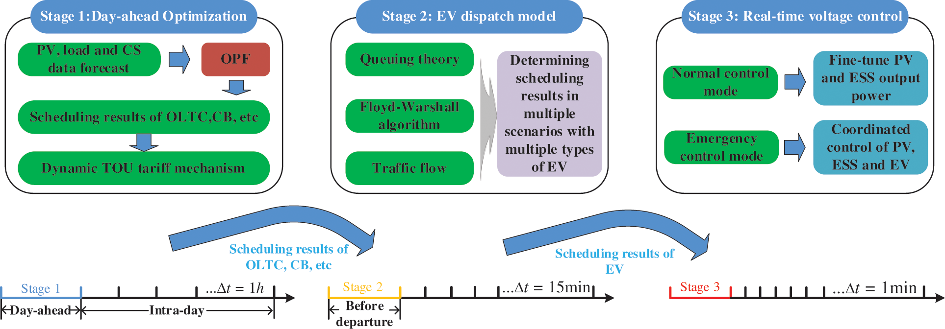
Figure 1: Simple queuing system model
Fig. 1 also reflects the coordination mechanisms for each stage. The results of actions such as OLTC and CB obtained in the first stage are sent to the second and third stages, while the node tariffs calculated based on the dynamic time-sharing tariff mechanism are also sent to the second stage. In the second stage, based on the nodal tariffs in the first stage, the EV scheduling results are updated every 15 min and sent to the third stage. Based on the OLTC and CB action results of the first stage and the EV scheduling results of the second stage, the third stage carries out real-time voltage control. Note that actually the third stage also feeds charging information to the second stage every 15 min.
3 Mathematical Formulation of Control Model
In this article, the proposed control model can be expressed as a mathematical formulation of three stages, which are related as follows.
3.1 Day-Ahead Optimal Centralized Control
3.1.1 Objective Functions and Constraints
Centralized control takes into consideration both voltage control effects, network losses and equipment regulation costs, and can be expressed as,
As you can see, the objective of this paper is a multi-objective function in which the voltage deviation penalty cost and the regulation cost of each device are mainly considered. The following are the constraints for centralized optimization:
Based on the DistFlow model after the second-order cone [29] relaxation, the power flow model is shown in Eqs. (2)–(5). Eqs. (2)–(4) represent the active power flow, reactive power flow and voltage relations in the power system, respectively. Eq. (5) is the convex relaxation of the power flow equation constraint. Eq. (6) gives the calculation formula of the voltage at node 1. Eq. (7) is the safety constraint for voltage.
Eq. (8) gives the calculation of CB reactive power output, while Eqs. (9) and (10) specify the upper and lower limits for the number of CB operation groups and the maximum number of adjustments per day, respectively. Eq. (11) ensures that the reactive power of the PV cannot exceed the inverter capacity limit. ESS is involved in voltage regulation auxiliary services [30], while the reactive power of ESS should be utilized as an inexpensive by-product. The model of ESS can be described as,
where Eqs. (12)–(14) give safety constraints on the charging and discharging power and ensure that charging and discharging cannot be performed simultaneously. Eqs. (15)–(17) indicate that the charging and discharging power must be within the inverter power capacity. Eq. (18) is the state of charge (SOC) formula for ESS, while Eq. (19) specifies the maximum and minimum values of SOC. Power to hydrogen (P2H) is a new type of load to cope with fluctuations in the output of new energy generation and reduce wind and light abandonment [31]. P2H produces hydrogen by electrolysis of water and generates some heat. The hydrogen can be stored in storage tanks for industrial production and fuel cars, etc. The heat can be used to supply heat loads, and a simplified schematic of its working principle is shown in Fig. 2. Existing studies tend to oversimplify the hydrogen production process of P2H to a conversion equation containing coefficients, however, this is hardly sufficient for the actual production of P2H. The P2H model in this paper is described as,
where Eqs. (20)–(25) describe the relationship between the start-up action, shutdown action and switching status of P2H, and limit the maximum number of start-ups and shutdowns per day. Note that the most mature and widely used alkaline electrolyzer, which has a 1-h start-up delay, is selected as the object of study in this paper. Eq. (26) is the formula for hydrogen production, while Eqs. (27) and (28) provide the maximum and minimum values for the electrolytic power of P2H.
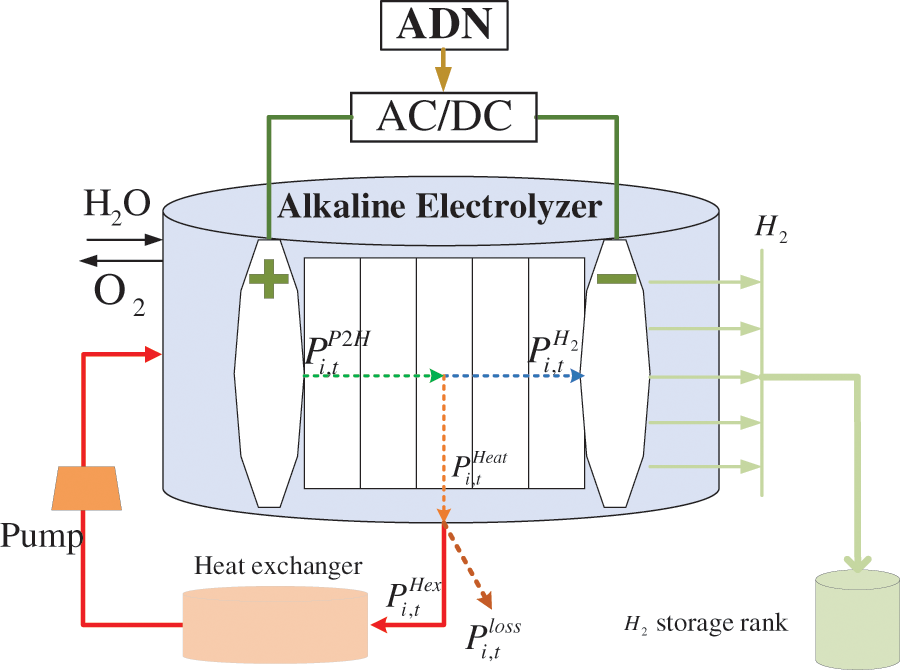
Figure 2: Schematic diagram of the working principle of P2H
It can be observed that Eqs. (6), (15) and (16) contain squared terms of the variables, which leads to the fact that the above problem is not directly solvable. Eq. (6) is transformed into solvable linear formulas by introducing binary variables [32].
Based on the circular interior polygon approach [33], Eqs. (15) and (16) can be reformulated as,
where
The optimization model is reconstructed as shown in (32) and (33), which is a mixed-integer second-order conic programming (MISOCP) model that can be solved quickly and efficiently using the gurobi solver [34].
3.1.2 Dynamic Time-of-Use Tariff Mechanism
The charging choice of EV users is influenced by the charging price. If a traditional static TOU tariff mechanism is adopted, the concentrated behavior of a great number of EVs may lead to new peaks and valleys in system load and result in queuing for EV charging. This paper proposes a dynamic TOU tariff mechanism that can dynamically adapt the charging price of CS according to the voltage level of the coupling nodes, thus reducing the voltage deviation.
It can be seen from Eq. (34) that the TOU tariff consists of two components, i.e., a fixed component and a variable component. The fixed component is determined by the cost of generation, transmission and distribution, subsidies for EV participation in orderly charging, battery losses, and other factors. The variable component is driven by the voltage at the coupling node, and the higher the voltage, the lower the tariff to direct EV charging and thus lower the voltage. The weights of the fixed and variable components are adjusted by
The rapid increase of different types of electric vehicles brings new opportunities and challenges to the distribution network voltage control, so the dispatch of electric vehicles is the core innovation point of the research in this paper.
3.2.1 Multiple Operating Scenarios for Multiple Types of EVs
Different types of EV users will consider different factors when making CS choices, while the most concerned factors include charging cost, charging time and waiting time, etc. Therefore, this paper considers the following five different operating scenarios for different types of EVs.
1) Scenario 1: A taxi in the normal working situation. In this scenario, the driver will assign the highest priority to the time cost, i.e., pursue the minimize total time costs, including travel time, waiting time and charging time. The driver will choose fast charging mode, as cost is not a major consideration.
2) Scenario 2: A private car to go shopping or dining. In this scenario, the driver will assign a higher weight to the travel time to get to the shopping mall or dining restaurant faster. The driver will choose the regular charging mode, since charging speed is not the main goal.
3) Scenario 3: A private car without special travel plans. In this scenario, the driver will assign a higher weight to the charging cost because the driver does not need to consider the time cost when no special trip is planned. The driver will select the regular charging mode.
4) Scenario 4: A bus that minimizes charging time. In this scenario, the bus company has a cooperation agreement with the CS to guarantee priority charging of the bus, so minimizing charging time becomes the primary goal of the driver. The driver will select the fast charging mode.
5) Scenario 5: A bus that finish charging by swapping batteries. Different from Scenario 4, the driver assigns a higher weight to the travel time to ensure that the CS is reached as soon as possible. Different from Scenario 2, the battery swap time often takes only a few minutes.
Note that the five scenarios above cannot include all scenarios that an EV driver may encounter, but they can be used as an example to provide a reference for a more comprehensive and in-depth study to follow.
3.2.2 Queueing Theory and Waiting Time Estimation
Queuing theory first originated in the study of telephone communication queuing wiring, after more than 100 years of development of its related theory has been more mature, its simplified model is shown in Fig. 3.
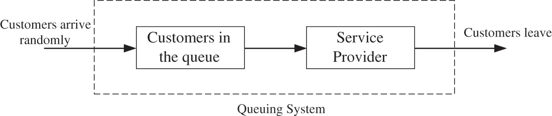
Figure 3: Simple queuing system model
In this paper, EVs are considered to determine the charging sequence based on the arrival sequence, which provides the basis for using the M/M/S model in queuing theory. According to [35], the waiting time can be evaluated in terms of two variables, i.e., the EV arrival rate
According to [36], the EV arrival rate follows a Poisson distribution, while the charge rate satisfies an exponential distribution. The probability that the kth arriving EV at time t can be charged in time at CS j is
where
Based on Eqs. (42), (43), the average length of queue can be expressed as Eq. (44).
The waiting time of EV at CS j is also given by Eq. (45).
3.2.3 Floyd-Warshall Algorithm and Travel Time Estimation
Shortest path is a fundamental problem in EV scheduling, and this paper uses the classical Floyd-Warshall algorithm to seek the shortest path. The process can be simplified as shown in Algorithm 1.
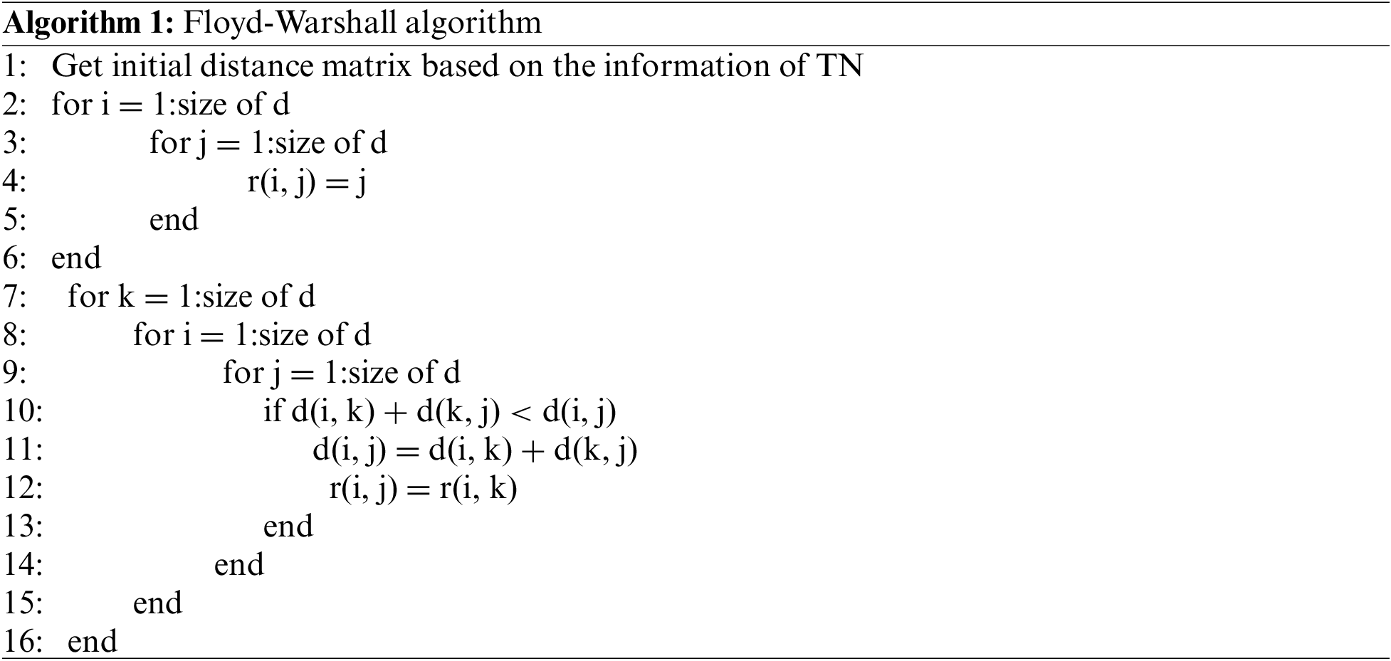
Firstly, the distance matrix is initialized based on the information of TN. d(i, j) denotes the distance between i and j. Secondly, we take the vertex k as the middle point to find the shortest path, where r(i, j) is the routing table. After finding the shortest path between the starting point and the CS, the travel time of the EV can be calculated by Eq. (46).
Note that
3.2.4 Charging Time Estimation
The charging time of EV is calculated by Eq. (47).
Note that
3.2.5 Charging Cost Estimation
The charging cost of EV is calculated by Eq. (48).
Eq. (48) represents the cost of charging required for EV fast charging or general charging.
3.2.6 SOC Calculation and Charging Selection Constraint for EV
The SOC of the EV still decreases during the process from the starting point to the CS, and the specific SOC calculation formula is shown in (49).
In addition, drivers can only choose one of the CSs as their destination, so there is the constraint as follows:
3.2.7 EV Scheduling Problem Construction
Based on the above model, EV scheduling can be constructed as the following optimization problem:
Note that Eq. (51) implies that the most suitable one from Eqs. (35)–(39) is chosen as the final objective function depending on the EV operation scenario, so that a mixed-integer linear programming (MILP) model is actually constructed for each scenario, which can be solved quickly with the gurobi solver.
3.3 Intra-Day Real-Time Voltage Control
In most studies, the power output of each control device is generally kept constant when the voltage is in the safe range, but this does not guarantee optimal control and minimal network losses. Therefore, in this paper, power fine-tuning is also performed for PV and ESS in normal control mode to achieve better voltage control effect and smaller network loss.
Note that different from the day-ahead centralized optimization, the output power of PV and ESS in the above real-time control is updated with a resolution of 1 min. The above problem is also a MISOCP model and can be solved quickly using the gurobi solver.
Once the voltage at any node is outside the safe range, the system will switch to emergency control mode. In addition to PV and ESS, EVs are also being introduced to participate in real-time voltage control by coupling to the ADN through CSs. The voltage-power sensitivity is first defined in (55).
It is assumed that voltage violation occurs at node i, then the reactive power adjustment of PV at node j is calculated as follows:
and, the active power adjustment of ESS and CS at node j is calculated as follows:
where
Note that the power adjustment value of the CS is achieved through the participation of EVs in voltage control. In order to ensure that each EV completes the charging as quickly as possible, the active power adjustment value of CS is reasonably allocated based on the fair voltage control mode in this paper, which can be expressed as follows:
thus, the active adjustment of EV i can be expressed as,
In addition, EVs need to meet the following constraints:
In this section, case simulations are performed and the results are analyzed in order to verify the performance of the proposed control model. Note that all mathematical models are written in program format in MATLAB 2020a. Also, the YALMIP toolbox with Gurobi 9.1.2 is used to solve the optimization problem.
4.1 Test System and Parameters Settings
As shown in Fig. 4, a 24-bus TN in Beijing coupled with a modified IEEE 33-bus ADN is simulated to validate the strategy in this paper. The parameters, access locations and unit regulation costs of the voltage regulation devices involved in this paper are listed in Table 1. Note that according to [37], a higher adjustment cost is set to minimize the action due to the higher maintenance cost of the OLTC mechanical action. The data of TN is shown in Table 2. Each CS is installed with 8 fast charging posts and 12 normal charging posts. The parameters in EV scheduling are listed in Table 3. In this paper five starting points are considered, located at nodes 7, 9, 11, 19 and 22. Note that the average speed of EVs from the starting point to the CS is changing, which is related to the traffic flow at each time period and can be statistically derived from historical data. The data of PV, load and CS load used in day-ahead centralized optimization are shown in Fig. 5. The data of PV and load in the intra-day real-time voltage control are shown in Fig. 6.
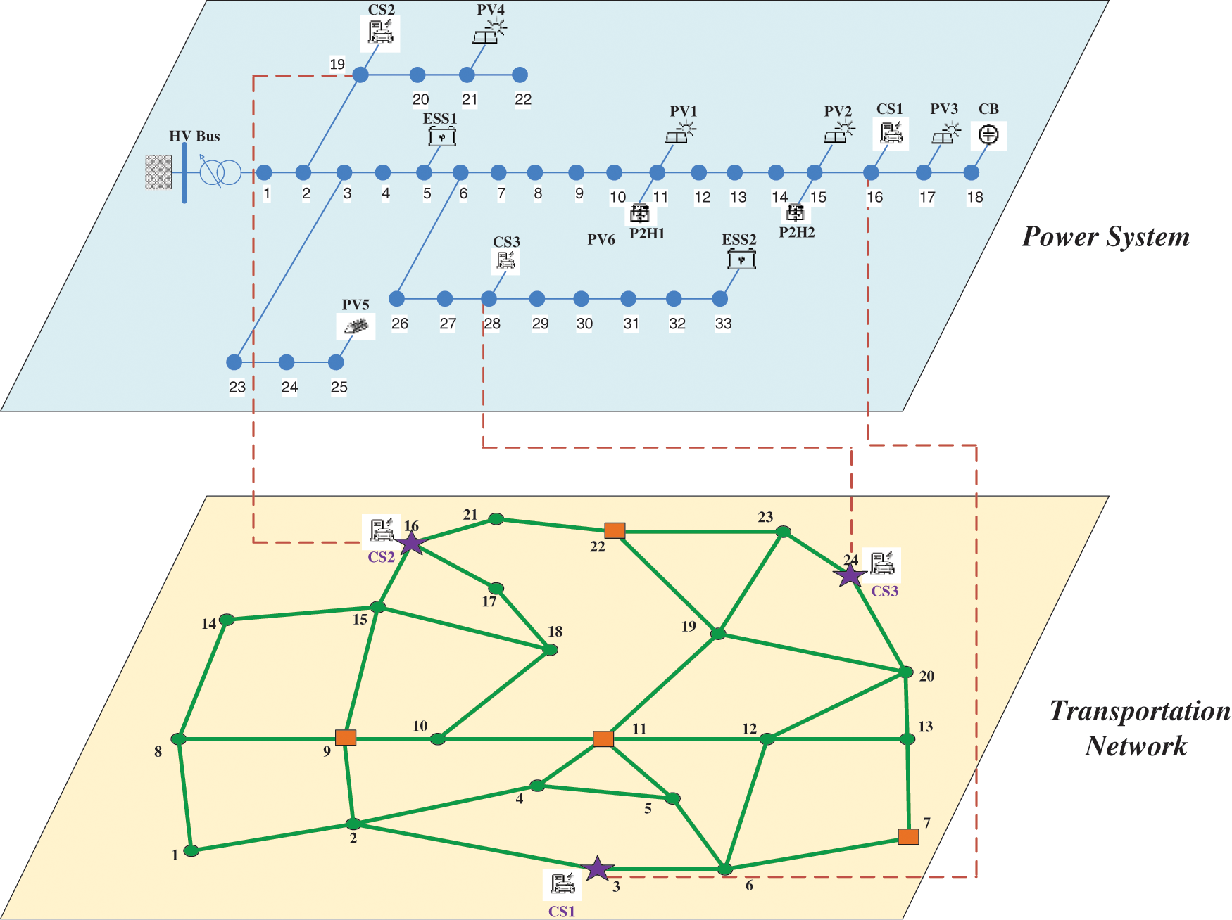
Figure 4: Topology diagram of the simulation system
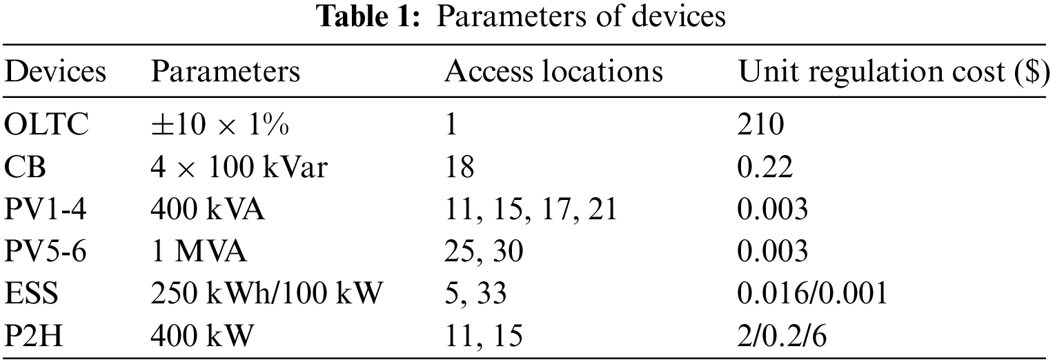
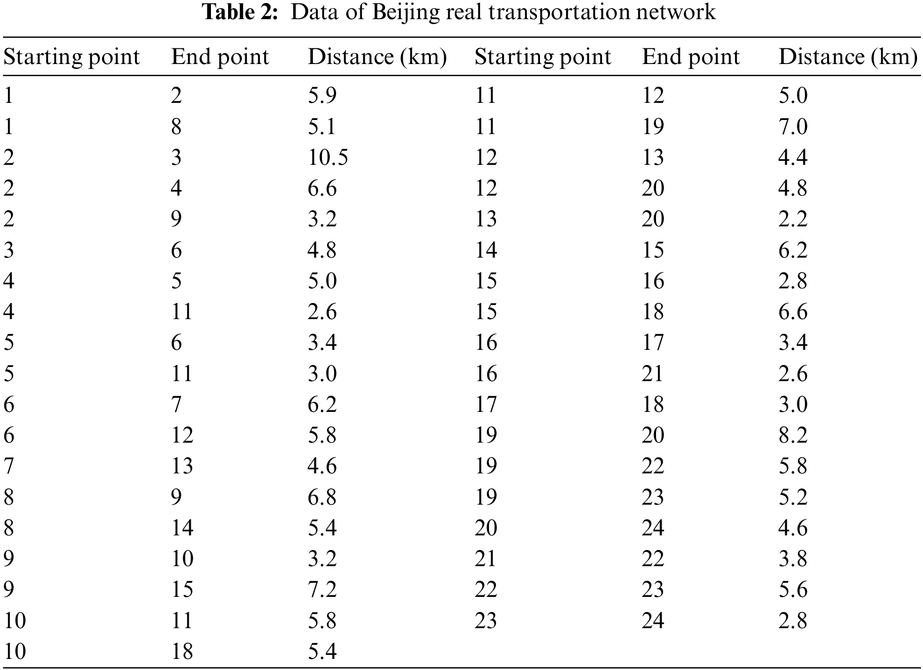
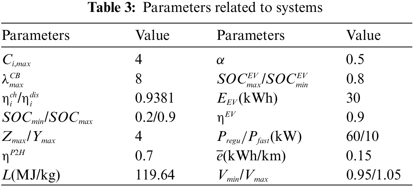
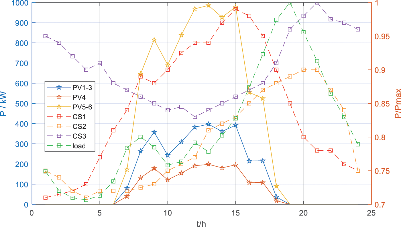
Figure 5: PV, CS and load variation curves in the day-ahead centralized optimization
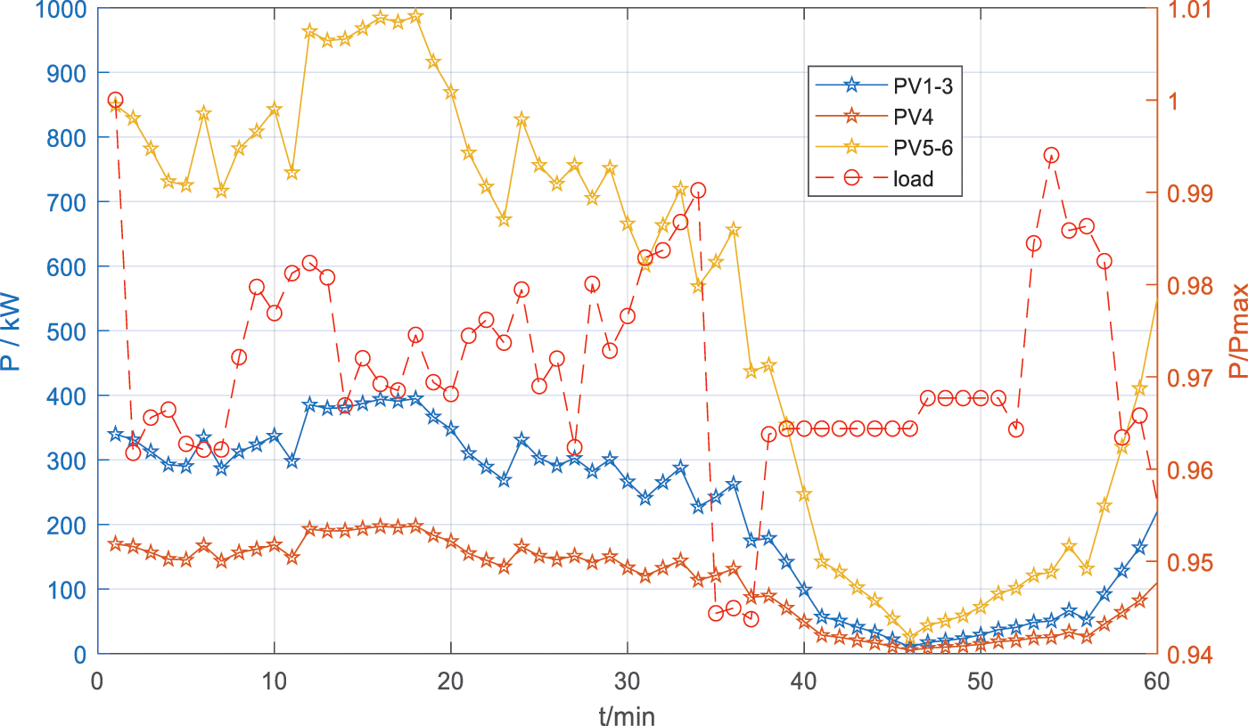
Figure 6: PV and load variation curves in intra-day real-time control
4.2 The Simulation Results of Day-Ahead Centralized Optimization
After day-ahead centralized optimization, the voltage amplitude of each node of the simulation system is shown in Fig. 7. It can be seen that the proposed strategy can control the voltage within the desired range despite the extreme cases of high PV output in the midday and high load in the evening. Fig. 8 shows the change curve of the throwing position of OLTC and CB, it can be seen that OLTC has no action throughout the day, while CB changes the throwing status from 2 to 3 at 16:00, which is analyzed because the reactive load is larger at night.
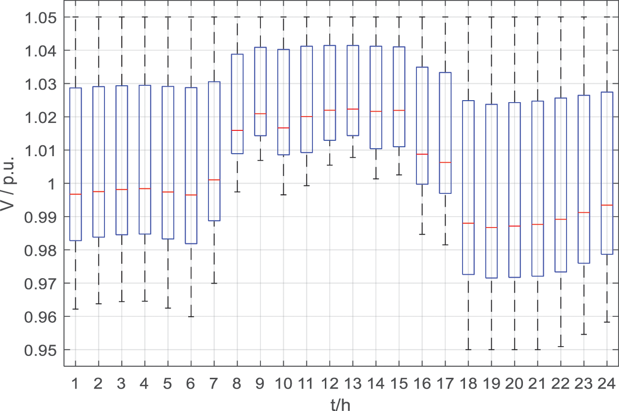
Figure 7: Voltage magnitude level after day-ahead optimization
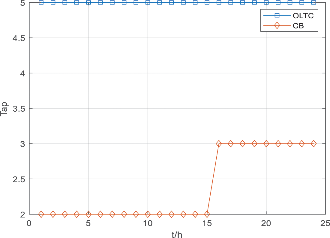
Figure 8: Variation curve of OLTC and CB throwing position
As shown in Fig. 9, the P2H electrolysis power is 0 in the evening, while the electrolysis power is gradually increased during the day when the PV output is high, so that a certain amount of PV power can be dissipated. In Fig. 10, the PV reactive power curve is shown. It can be seen that each PV shows a similar pattern of variation, where the power output is greater in the evening hours.
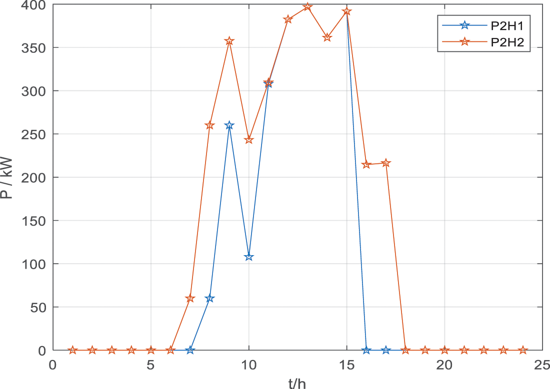
Figure 9: Electrolytic power variation curve of P2H
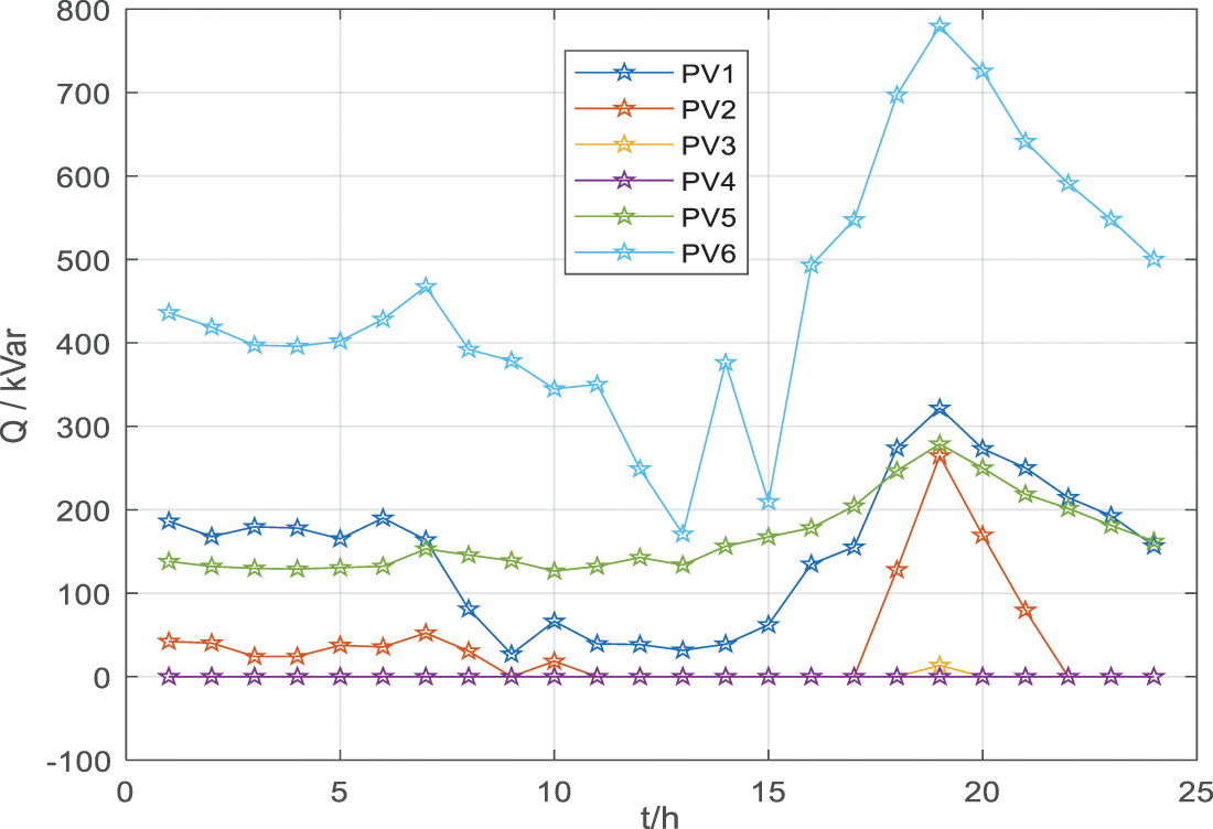
Figure 10: Reactive power curve of PV
This subsection validates the EV scheduling model, and the related results are shown in Figs. 11–13 and Table 4. Note that for the convenience of study and presentation, we only study the scheduling decision of EVs at starting point 3, and the related results can be extended to the scheduling study of EVs at all starting points.
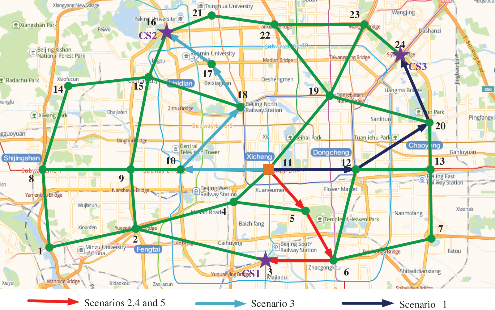
Figure 11: EV scheduling and route planning results for different scenarios
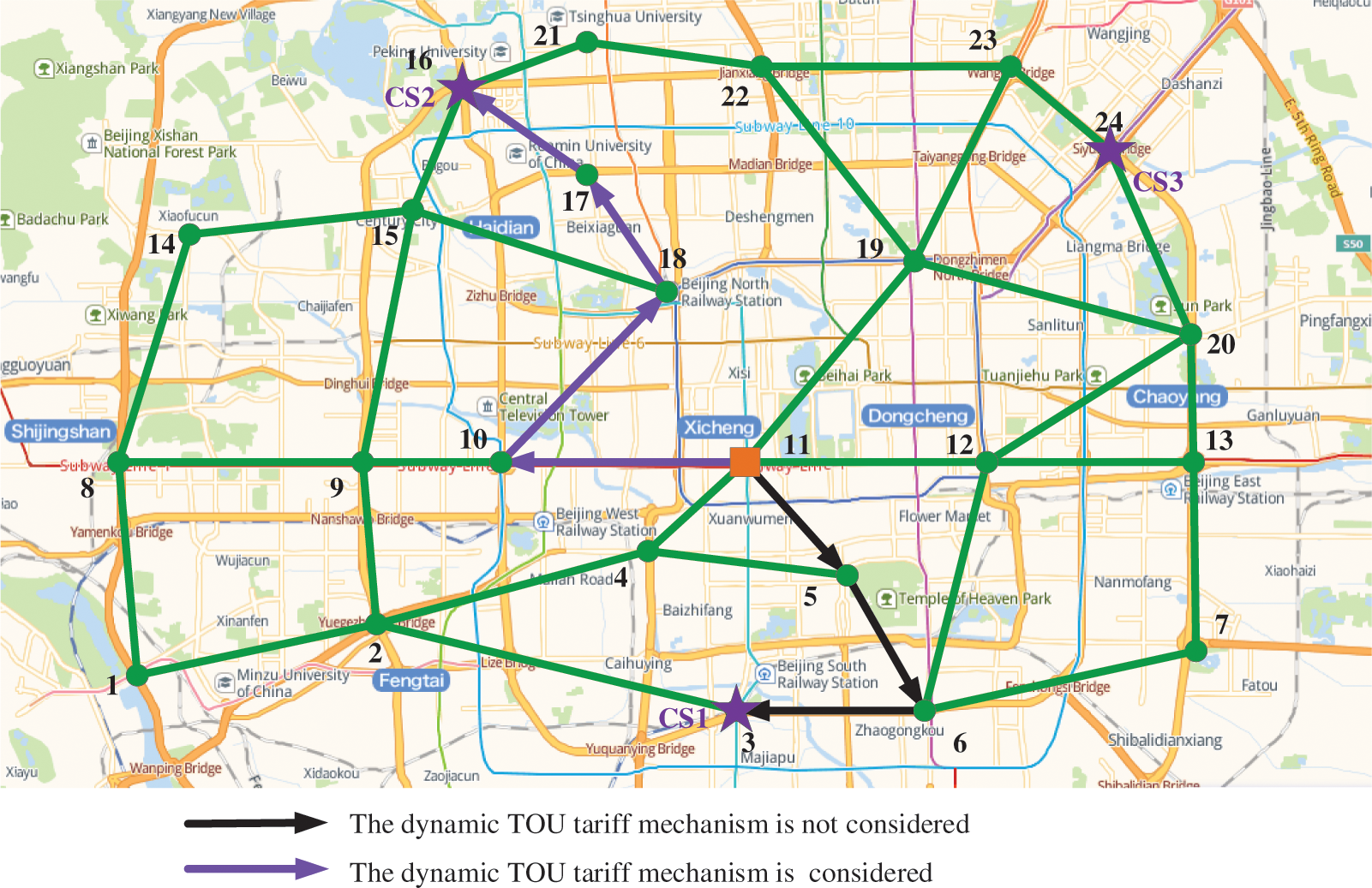
Figure 12: Comparison of dispatching in Scenario 3 with and without dynamic TOU mechanism
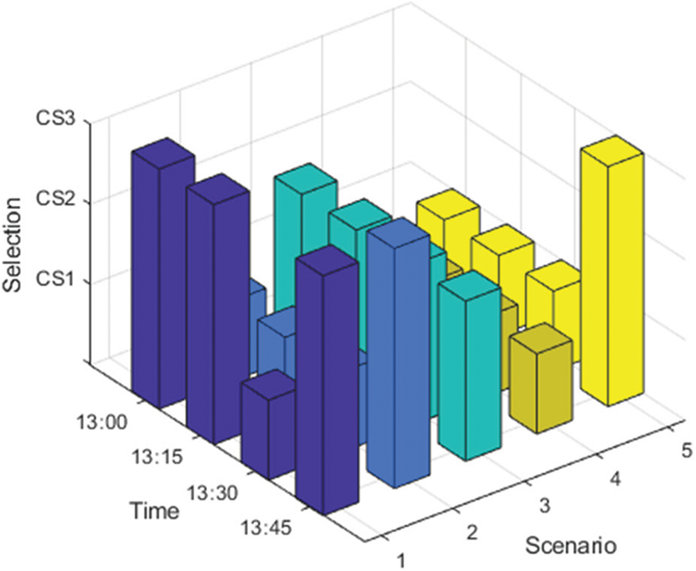
Figure 13: Choice of CSs at different times for EVs in each scenario
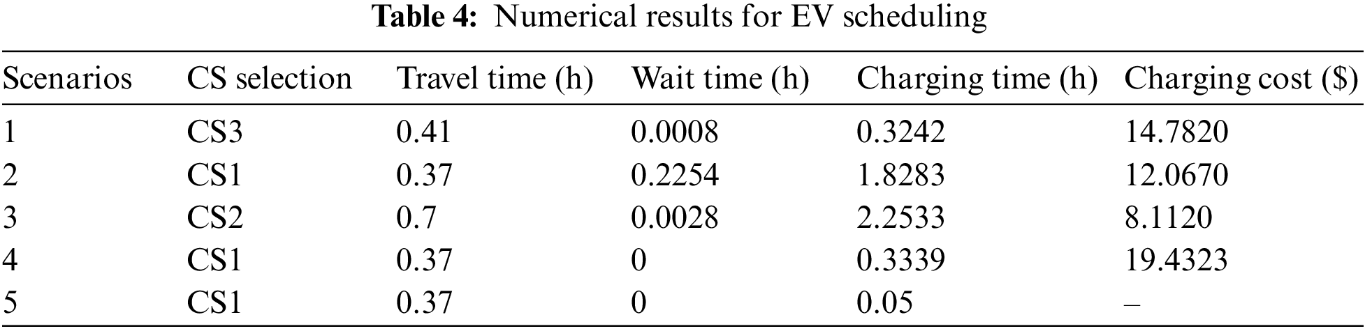
Fig. 11 shows the scheduling results for the five scenarios, and it can be seen that they exhibit significant differences. Specifically, Scenario 2 seeks only the shortest driving time, so the driver chooses CS1 as the target CS. And the buses in Scenarios 4 and 5 have similar targets, so their scheduling results are consistent with Scenario 2. However, the private car in Scenario 3 pursues the minimum charging cost and does not consider the time factor, which leads to the obvious difference between his scheduling results and those in other scenes. To further detail the effectiveness of the scheduling model, the relevant numerical results are presented in Table 4. It can be seen that Scenario 1 can achieve the smallest total time cost, but the charging cost is not the lowest. Note that the time cost of Scenario 4 appears to be smaller, but this is because the bus company has a contract with the charging station so that there is no waiting. The charging cost of the private car in Scenario 3 is the smallest, but its various time costs are larger.
To illustrate the effectiveness of the dynamic TOU tariff mechanism, relevant comparison results are shown in Fig. 12. Without considering the dynamic TOU tariff mechanism (i.e., static tariff mechanism), private cars in Scenario 3 will choose to charge in CS1 in order to minimize charging cost. Such a large number of EV loads will bring more serious voltage problems to node 16 coupled with CS1. Compared with node 16 coupled to CS1, node 19 coupled to CS2 has a higher voltage amplitude and a cheaper tariff calculated based on the dynamic TOU tariff mechanism, so the EV chooses CS2 as the charging destination, which helps prevent voltage crossing accidents.
To further validate the scheduling results of EVs for each scenario at different time periods, a bar chart depicting the results of CS selection is plotted in Fig. 13. It can be seen that the EV of Scenario 3 always selects CS2 for charging in the four time periods, while the EV of Scenario 4 selects CS1. EV of Scenario 1 selects CS1 at 13:30–13:45, while CS3 at other time periods, which is analyzed to be related to changes in traffic flow and the number of cars waiting at the CS in relevant time periods. For the EVs in Scenarios 2 and 5, they both pursue the shortest travel time and show a similar change pattern in CS selection, i.e., they choose CS1 from 13:00–13:45 and choose CS3 from 13:45–14:00. Under the condition that the shortest path distance between the starting point and each CS remains unchanged, we analyzed that the reason for changing the selection of CS is that the change of average speed caused by the change of traffic flow, which leads to a shorter time for the EV to go to CS3 from 13:45–14:00.
4.4 Simulation Results of Real-Time Voltage Control
Three existing methods are compared to demonstrate the superiority of the method proposed in this paper.
1) Method *1: Single-layer voltage control model. In this control model, only day-ahead centralized optimization is considered and voltage violations are mitigated using OLTC, CB, PV and ESS optimal output power, etc., calculated based on 1-hour resolution. A related study can be found in [38].
2) Method *2: Two-layer voltage control model. In this control model, day-ahead centralized optimization and EV routing scheduling are performed to further reduce voltage deviations. A related study can be found in [39].
3) Method *3: Three-layer voltage control model. In this control model, three layers of control framework are included: day-ahead centralized optimization, EV route scheduling and intra-day real-time control. However, different from this paper, its intra-day control only considers EV control strategies to mitigate voltage deviations. A related study can be found in [40].
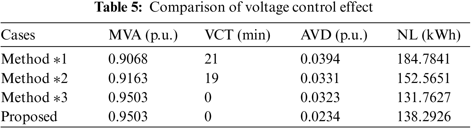
First of all, Fig. 14 gives the voltage magnitudes of all nodes over 60 min after control with the method in this paper, and it can be seen that the proposed method can control the voltage in the range of [0.95 1.05] although there is a significant decrease in PV active power from 13:35. In Fig. 15, it can be seen that method *1 and method *2 do not cope well with the sudden and significant drop in PV output power and produce large voltage deviations. Both method *3 and the method proposed in this paper can control the voltage within the safe range without voltage violations, but method *3 has a larger average voltage deviation. To compare the voltage control effects of the various methods more specifically, the minimum voltage amplitude (MVA), voltage crossing time (VCT), average voltage deviation (AVD) and network losses (NL) are listed in Table 5. It can be seen that the proposed method has the smallest average voltage deviation and achieves the best voltage control effect. From the network loss data in the last column, the loss of method *1 is the largest, and method *3 can achieve the smallest network loss. The network loss of the proposed method is improved by 4.96% compared to method *3, but the average voltage deviation can be reduced by 27.6%, which is considered to be worthwhile.
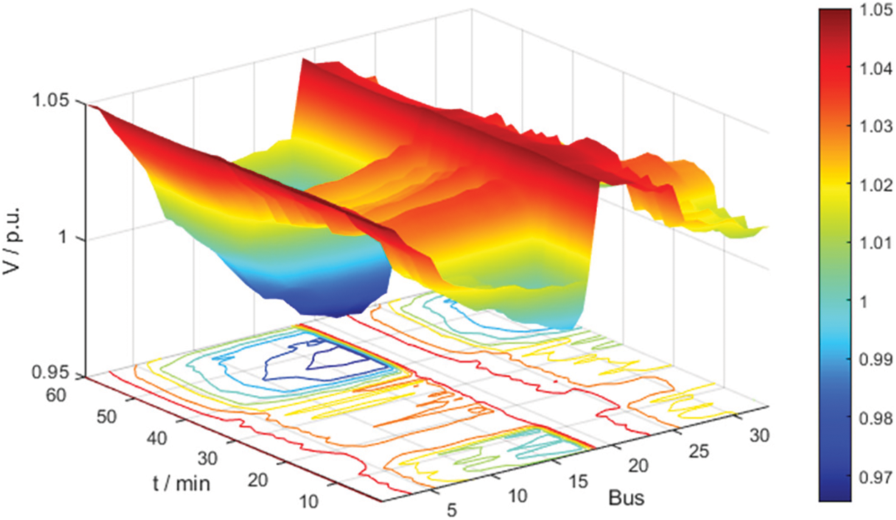
Figure 14: Voltage at all buses at all times with proposed method
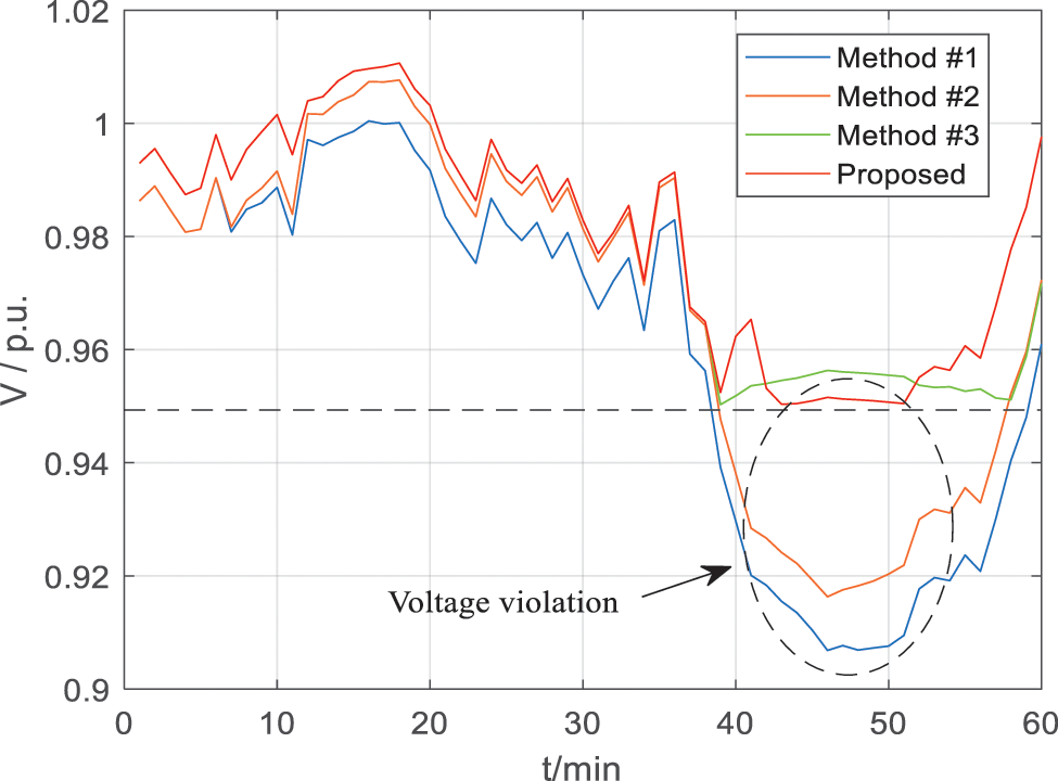
Figure 15: Voltage curve of bus 18 after different methods of control
To further illustrate the effect of real-time control, CS2 is used as an example in this paper for further analysis. Fig. 16 shows the relationship between the EV power adjustment value in CS2 and the voltage of bus 18. It can be seen that in the normal voltage control mode, the EV is not involved in voltage control to prioritize its charging process. In the emergency control mode, the EV also regulates its charging power to prioritize the voltage violation problem. Specifically, from 13:39 to 13:51, when the EV regulates its charging power, the voltage profile of bus 18 is the red line in the figure, and the voltage deviation is significantly reduced and no voltage violation occurs compared to the blue line (i.e., the EV does not participate in voltage control). Fig. 17 shows the results of the distribution of power adjustment values within the CS based on the fair voltage control mode. Fig. 17a corresponds to an EV with a small initial SOC, while Fig. 17b corresponds to an EV with a larger initial SOC. It can be seen that the maximum power adjustment value in Fig. 17a is about 12 kW, while Fig. 17b is about 30 kW, which is more helpful to reduce the impact of participating voltage control auxiliary services on EVs with smaller initial SOC and to achieve a balance between EVs with different initial SOC.
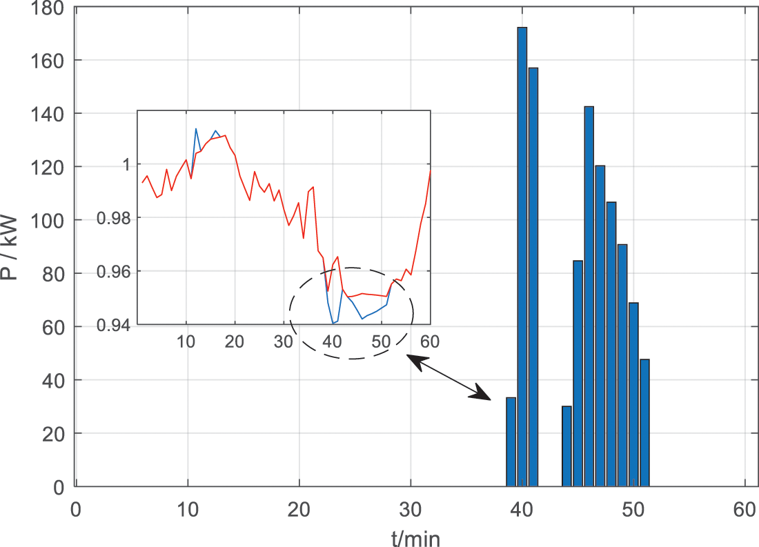
Figure 16: Power adjustment of CS2 and voltage amplitude change of bus 18
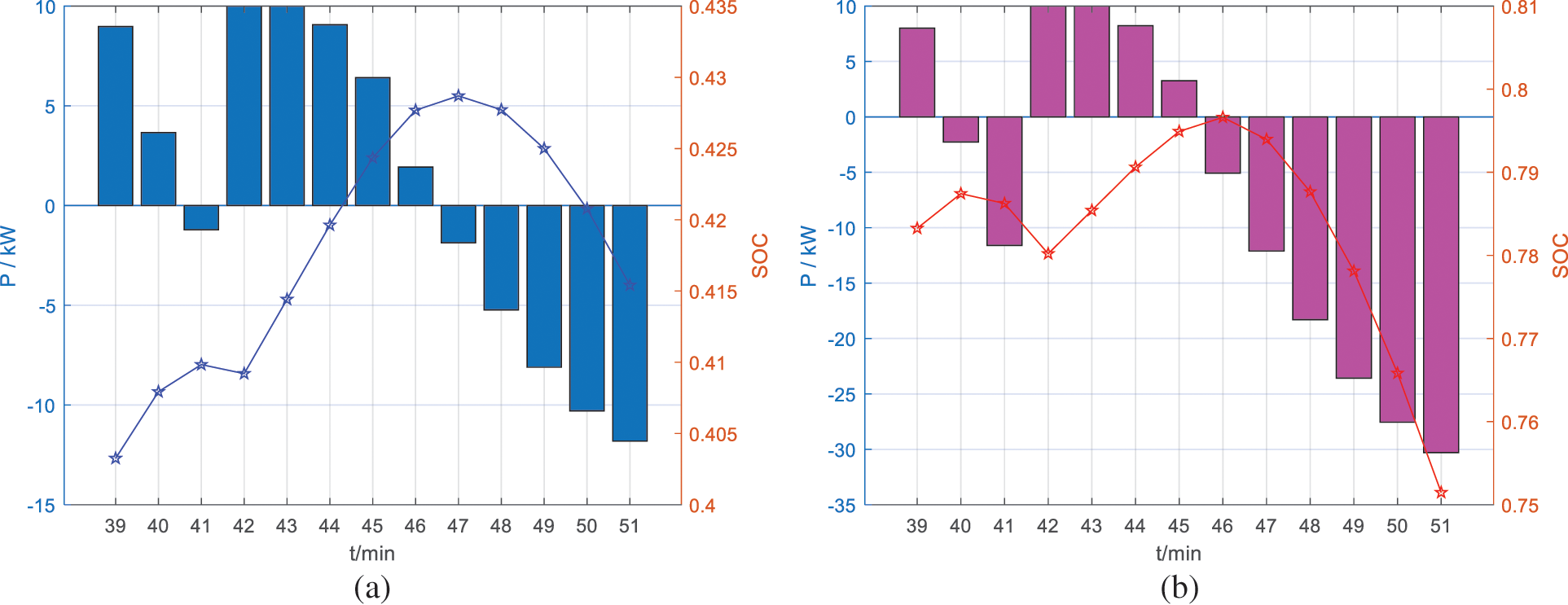
Figure 17: Active power and SOC curves of electric vehicles: (a) EVs with low SOC, (b) EVs with high SOC
This paper proposes a three-layer voltage control scheme considering multiple types of EVs, which enables the coordination of voltage regulation devices with different action speeds and provides a personalized solution for CS selection and route navigation for EV drivers. Three conclusions are drawn by case simulation: 1) Considering multiple operation scenarios of multiple types of EVs, all types of voltage regulation resources can be dispatched more rationally. 2) In EV scheduling, there are differences in scheduling results for different time periods, and voltage scheduling solutions should be developed taking into account the overall interests of the city and the individual interests of drivers. 3) In real-time control, coordinated control of EV with other control equipment can reduce the average voltage deviation by 27.6% compared with EV control alone, although it will lead to a 4.96% increase in network loss, but it is worthwhile.
Although the proposed scheme can mitigate voltage violations well, it is carried out under the condition that data such as distribution network topology and line impedance are accurately obtained, which may be limited in realistic concrete applications. The future research direction may be the study of voltage control strategies under incomplete information, which tends to be solved based on artificial intelligence methods such as deep reinforcement learning algorithms.
Acknowledgement: The authors would like to thank the editorial and reviewer panel for their input and comments.
Funding Statement: This work is supported by the Science and Technology Project of North China Electric Power Research Institute, which is “Research on Key Technologies for Power Quality Evaluation and Improvement of New Distribution Network Based on Collaborative Interaction of Source-Network-Load-Storage”(KJZ2022016).
Author Contributions: The authors confirm contribution to the paper as follows: study conception and design: L. L., G. X.; data collection: Y. Z.; analysis and interpretation of results: Y. L., Y. L.; draft manuscript preparation: J. G., L. L. All authors reviewed the results and approved the final version of the manuscript.
Availability of Data and Materials: Data sharing is not applicable to this article as no new data were created or analyzed in this study.
Conflicts of Interest: The authors declare that they have no conflicts of interest to report regarding the present study.
References
1. Liu, Y., Wang, Y., Li, Y., Gooi, H. B., Xin, H. (2021). Multi-agent based optimal scheduling and trading for multi-microgrids integrated with urban transportation networks. IEEE Transactions on Power Systems, 36(3), 2197–2210. https://doi.org/10.1109/TPWRS.2020.3040310 [Google Scholar] [CrossRef]
2. Ministry of Public Security of the People's Republic of China (2023). National motor vehicle fleet reaches 417 million vehicles with over 500 million drivers. https://app.mps.gov.cn/gdnps/pc/content.jsp?id=8837602 [Google Scholar]
3. Ismael, S. M., Abdel Aleem, S. H. E., Abdelaziz, A. Y., Zobaa, A. F. (2019). State-of-the-art of hosting capacity in modern power systems with distributed generation. Renewable Energy, 130, 1002–1020. https://doi.org/10.1016/j.renene.2018.07.008 [Google Scholar] [CrossRef]
4. National Energy Administration of China (2023). The National Energy Administration released 2022 national electricity industry statistics. http://www.nea.gov.cn/2023-01/18/c_1310691509.htm [Google Scholar]
5. Chen, H., Hu, Z., Luo, H., Qin, J., Rajagopal, R. et al. (2019). Design and planning of a multiple-charger multiple-port charging system for PEV charging station. IEEE Transactions on Smart Grid, 10(1), 173–183. https://doi.org/10.1109/TSG.2017.2735636 [Google Scholar] [CrossRef]
6. Zhang, Y., Chen, J., Zhao, H., Zhang, W., Jiao, W. et al. (2023). Coordinated voltage control of active distribution networks with photovoltaic and power to hydrogen. Energy Systems Integration, https://doi.org/10.1049/esi2.12096 [Google Scholar] [CrossRef]
7. Jafari, M.R , Parniani, M., Ravanji, M. H. (2022). Decentralized control of OLTC & PV inverters for voltage regulation in radial distribution networks with high PV penetration. IEEE Transactions on Power Delivery, 37(6), 4827–4837. https://doi.org/10.1109/TPWRD.2022.3160375 [Google Scholar] [CrossRef]
8. Cao, D., Hu, W., Zhao, J., Huang, Q., Chen, Z. et al. (2020). A multi-agent deep reinforcement learning based voltage regulation using coordinated PV inverters. IEEE Transactions on Power Systems, 35(5), 4120–4123. https://doi.org/10.1109/TPWRS.2020.3000652 [Google Scholar] [CrossRef]
9. Cao, X., Cao, T., Xu, Z., Zeng, B., Gao, F. et al. (2023). Resilience constrained scheduling of mobile emergency resources in electricity-hydrogen distribution network. IEEE Transactions on Sustainable Energy, 14(2), 1269–1284. https://doi.org/10.1109/TSTE.2022.3217514 [Google Scholar] [CrossRef]
10. Lai, S., Qiu, J., Tao, Y., Zhao, J. (2023). Pricing for electric vehicle charging stations based on the responsiveness of demand. IEEE Transactions on Smart Grid, 14(1), 530–544. https://doi.org/10.1109/TSG.2022.3188832 [Google Scholar] [CrossRef]
11. Dong, X., Mu, Y., Xu, X., Jia, H., Wu, J. et al. (2018). A charging pricing strategy of electric vehicle fast charging stations for the voltage control of electricity distribution networks. Applied Energy, 225, 857–868. https://doi.org/10.1016/j.apenergy.2018.05.042 [Google Scholar] [CrossRef]
12. Yue, H., Zhang, Q., Zeng, X., Huang, W., Zhang, L. et al. (2023). Optimal scheduling strategy of electric vehicle cluster based on index evaluation system. IEEE Transactions on Industry Applications, 59(1), 1212–1221. https://doi.org/10.1109/TIA.2022.3213639 [Google Scholar] [CrossRef]
13. Liu, Y., Cheng, C., Shi, H., Zuo, X., Chen, S. (2022). A two-stage approach with a departure time based solution representation for electric bus vehicle scheduling. IEEE Access, 10, 112799–112811. https://doi.org/10.1109/ACCESS.2022.3215592 [Google Scholar] [CrossRef]
14. Liu, W., Gong, Y., Chen, W., Liu, Z., Wang, H. et al. (2020). Coordinated charging scheduling of electric vehicles: A mixed-variable differential evolution approach. IEEE Transactions on Intelligent Transportation Systems, 21(12), 5094–5109. https://doi.org/10.1109/TITS.2019.2948596 [Google Scholar] [CrossRef]
15. Das, S., Acharjee, P., Bhattacharya, A. (2021). Charging scheduling of electric vehicle incorporating grid-to-vehicle and vehicle-to-grid technology considering in smart grid. IEEE Transactions on Industry Applications, 57(2), 1688–1702. https://doi.org/10.1109/TIA.2020.3041808 [Google Scholar] [CrossRef]
16. Li, Y., Han, M., Yang, Z., Li, G. (2021). Coordinating flexible demand response and renewable uncertainties for scheduling of community integrated energy systems with an electric vehicle charging station: A bi-level approach. IEEE Transactions on Sustainable Energy, 12(4), 2321–2331. https://doi.org/10.1109/TSTE.2021.3090463 [Google Scholar] [CrossRef]
17. Malisani, P., Zhu, J., Pognant-Gros, P. (2023). Optimal charging scheduling of electric vehicles: The co-charging case. IEEE Transactions on Power Systems, 38(2), 1069–1080. https://doi.org/10.1109/TPWRS.2022.3172286 [Google Scholar] [CrossRef]
18. Kapoor, A., Patel, V. S., Sharma, A., Mohapatra, A. (2022). Centralized and decentralized pricing strategies for optimal scheduling of electric vehicles. IEEE Transactions on Smart Grid, 13(3), 2234–2244. https://doi.org/10.1109/TSG.2022.3141261 [Google Scholar] [CrossRef]
19. Wu, F., Yang, J., Zhan, X., Liao, S., Xu, J. (2021). The online charging and discharging scheduling potential of electric vehicles considering the uncertain responses of users. IEEE Transactions on Power Systems, 36(3), 1794–1806. https://doi.org/10.1109/TPWRS.2020.3029836 [Google Scholar] [CrossRef]
20. Wang, Y., John, T., Xiong, B. (2019). A two-level coordinated voltage control scheme of electric vehicle chargers in low-voltage distribution networks. Electric Power Systems Research, 168, 218–227. https://doi.org/10.1016/j.epsr.2018.12.005 [Google Scholar] [CrossRef]
21. Hoque, M. M., Khorasany, M., Razzaghi, R., Wang, H., Jalili, M. (2022). Transactive coordination of electric vehicles with voltage control in distribution networks. IEEE Transactions on Sustainable Energy, 13(1), 391–402. https://doi.org/10.1109/TSTE.2021.3113614 [Google Scholar] [CrossRef]
22. Li, H., Azzouz, M. A., Hamad, A. A. (2021). Cooperative voltage control in MV distribution networks with electric vehicle charging stations and photovoltaic DGs. IEEE Systems Journal, 15(2), 2989–3000. https://doi.org/10.1109/JSYST.2020.3001040 [Google Scholar] [CrossRef]
23. Hu, J., Ye, C., Ding, Y., Tang, J., Liu, S. (2022). A distributed MPC to exploit reactive power V2G for real-time voltage regulation in distribution networks. IEEE Transactions on Smart Grid, 13(1), 576–588. https://doi.org/10.1109/TSG.2021.3109453 [Google Scholar] [CrossRef]
24. Singh, S., Pamshetti, V. B., Singh, S. P. (2019). Time horizon-based model predictive Volt/VARoptimization for smart grid enabled CVR in the presence of electric vehicle charging loads. IEEETransactions on Industry Applications, 55(6), 5502–5513. https://doi.org/10.1109/TIA.2019.2928490 [Google Scholar] [CrossRef]
25. Wang, Y., Qiu, D., Strbac, G., Gao, Z. (2023). Coordinated electric vehicle active and reactive power control for active distribution networks. IEEE Transactions on Industrial Informatics, 19(2), 1611–1622. https://doi.org/10.1109/TII.2022.3169975 [Google Scholar] [CrossRef]
26. Kim, D., Kim, B., Yoon, C., Nguyen, N., Lee, Y. I. (2023). Disturbance observer-based model predictive voltage control for electric-vehicle charging station in distribution networks. IEEE Transactions on Smart Grid, 14(1), 545–558. https://doi.org/10.1109/TSG.2022.3187120 [Google Scholar] [CrossRef]
27. Prabawa, P., Choi, D. (2021). Hierarchical Volt-VAR optimization framework considering voltage control of smart electric vehicle charging stations under uncertainty. IEEE Access, 9, 123398–123413. https://doi.org/10.1109/ACCESS.2021.3109621 [Google Scholar] [CrossRef]
28. Ji, C., Liu, Y., Lyu, L., Li, X., Liu, C. et al. (2020). A personalized fast-charging navigation strategy based on mutual effect of dynamic queuing. IEEE Transactions on Industry Applications, 56(5), 5729–5740. https://doi.org/10.1109/TIA.2020.2985641 [Google Scholar] [CrossRef]
29. Baran, M. E., Wu, F. F. (1989). Network reconfiguration in distribution systems for loss reduction and load balancing. IEEE Transactions on Power Delivery, 4(2), 1401–1407. https://doi.org/10.1109/61.25627 [Google Scholar] [CrossRef]
30. Liu, X., Soh, C. B., Zhao, T., Wang, P. (2021). Stochastic scheduling of mobile energy storage in coupled distribution and transportation networks for conversion capacity enhancement. IEEE Transactions on Smart Grid, 12(1), 117–130. https://doi.org/10.1109/TSG.2020.3015338 [Google Scholar] [CrossRef]
31. Chen, X., McElroy, M. B., Kang, C. (2018). Integrated energy systems for higher wind penetration in china: Formulation, implementation, and impacts. IEEE Transactions on Power Systems, 33(2), 1309–1319. https://doi.org/10.1109/TPWRS.2017.2736943 [Google Scholar] [CrossRef]
32. Li, P., Ji, H., Wang, C., Zhao, J., Song, G. et al. (2017). Coordinated control method of voltage and reactive power for active distribution networks based on soft open point. IEEE Transactions on Sustainable Energy, 8(4), 1430–1442. https://doi.org/10.1109/TSTE.2017.2686009 [Google Scholar] [CrossRef]
33. Sun, H., Zhang, L., Xu, H., Wang, L. (2015). Mixed integer programming model for microgrid intra-day scheduling. Automation of Electric Power Systems, 39(19), 21–27. https://doi.org/10.7500/AEPS20141117011 [Google Scholar] [CrossRef]
34. Ji, H., Wang, C., Li, P., Zhao, J., Song, G. et al. (2018). A centralized-based method to determine the local voltage control strategies of distributed generator operation in active distribution networks. Applied Energy, 228, 2024–2036. https://doi.org/10.1016/j.apenergy.2018.07.065 [Google Scholar] [CrossRef]
35. Yang, H., Deng, Y., Qiu, J., Li, M., Lai, M. et al. (2017). Electric vehicle route selection and charging navigation strategy based on crowd sensing. IEEE Transactions on Industrial Informatics, 13(5), 2214–2226. https://doi.org/10.1109/TII.2017.2682960 [Google Scholar] [CrossRef]
36. Hafez, O., Bhattacharya, K. (2018). Integrating EV charging stations as smart loads for demand response provisions in distribution systems. IEEE Transactions on Smart Grid, 9(2), 1096–1106. https://doi.org/10.1109/TSG.2016.2576902 [Google Scholar] [CrossRef]
37. Wang, P., Liang, D. H., Yi, J., Lyons, P. F., Davison, P. J. et al. (2014). Integrating electrical energy storage into coordinated voltage control schemes for distribution networks. IEEE Transactions on Smart Grid, 5(2), 1018–1032. https://doi.org/10.1109/TSG.2013.2292530 [Google Scholar] [CrossRef]
38. Yang, H., Yang, S., Xu, Y., Cao, E., Lai, M. et al. (2015). Electric vehicle route optimization considering time-of-use electricity price by learnable partheno-genetic algorithm. IEEE Transactions on Smart Grid, 6(2), 657–666. https://doi.org/10.1109/TSG.2014.2382684 [Google Scholar] [CrossRef]
39. Qian, T., Shao, C., Li, X., Wang, X., Shahidehpour, M. (2020). Enhanced coordinated operations of electric power and transportation networks via EV charging services. IEEE Transactions on Smart Grid, 11(4), 3019–3030. https://doi.org/10.1109/TSG.2020.2969650 [Google Scholar] [CrossRef]
40. Sun, X., Qiu, J. (2021). Hierarchical voltage control strategy in distribution networks considering customized charging navigation of electric vehicles. IEEE Transactions on Smart Grid, 12(6), 4752–4764. https://doi.org/10.1109/TSG.2021.3094891 [Google Scholar] [CrossRef]
Cite This Article
 Copyright © 2024 The Author(s). Published by Tech Science Press.
This work is licensed under a Creative Commons Attribution 4.0 International License , which permits unrestricted use, distribution, and reproduction in any medium, provided the original work is properly cited.
 Downloads
 Citation Tools