
 Submit a Paper
 Propose a Special lssue
 Open Access
ARTICLE

Electro-Optical Model of Soiling Effects on Photovoltaic Panels and Performance Implications
1 Laboratory of Materials and Renewable Energies, University Ibn Zohr, Agadir, 80000, Morocco
2 Sol Ideas Technology Development, San José, 95150, USA
* Corresponding Author: A. Asbayou. Email:
Energy Engineering 2024, 121(2), 243-258. https://doi.org/10.32604/ee.2024.046409
Received 29 September 2023; Accepted 16 November 2023; Issue published 25 January 2024
 View Full Text
 Download PDF
Abstract
In this paper, a detailed model of a photovoltaic (PV) panel is used to study the accumulation of dust on solar panels. The presence of dust diminishes the incident light intensity penetrating the panel’s cover glass, as it increases the reflection of light by particles. This phenomenon, commonly known as the “soiling effect”, presents a significant challenge to PV systems on a global scale. Two basic models of the equivalent circuits of a solar cell can be found, namely the single-diode model and the two-diode models. The limitation of efficiency data in manufacturers’ datasheets has encouraged us to develop an equivalent electrical model that is efficient under dust conditions, integrated with optical transmittance considerations to investigate the soiling effect. The proposed approach is based on the use of experimental current-voltage (I-V) characteristics with simulated data using MATLAB/Simulink. Our research outcomes underscores the feasibility of accurately quantifying the reduction in energy production resulting from soiling by assessing the optical transmittance of accumulated dust on the surface of PV glass.Graphic Abstract

Keywords
Nomenclature
| λ | Wavelength (μm) |
| θ | The angle of incidence of light on the PV panel |
| a | Parameter related to the average particle size of dust |
| b | Parameter related to the particle surface concentration |
| T(λ) | Transmittance (dimensionless, 0 to 1.0) |
| α0 | Temperature correction coefficient for current (°C−1) |
| β0 | Temperature correction coefficient for voltage (°C−1) |
| G | Solar irradiance on the module PV (W/m2) |
| Gref | Reference solar irradiance on the module PV (Gref = 103 W/m2) |
| Iph | Photo-generated current (A) |
| I | Solar cell (or photovoltaic) terminal output current (A) |
| ISC | Short circuit current (A) |
| I0 | Reverse saturation current (A) |
| I0i | Reverse saturation current of diode i in the conventional model (A) |
| ni | Diode ideality factor |
| NS | Cell number connected in series |
| Nsh | Cell number connected in shunt |
| PV | Photovoltaic |
| P | Power (W) |
| Rs | Series resistance (Ω) |
| Rsh | Shunt resistance (Ω) |
| STC | Standard test conditions (Gref = 1000 W/m2, T0 = 25°C, and AM = 1.5) |
| T | Cell or module operating temperature (°C) |
| Ta | Ambient temperature (°C) |
| ∆T | Temperature difference: = T − T0 (°C) |
| VOC | Solar cell open-circuit voltage (V) |
| V | Solar cell (or photovoltaic) terminal output voltage (V) |
| Eg | Bandgap energy |
| q | 1.60217662 × 10⁻¹⁹ C, the elementary charge |
| h | 6.62607004 × 10⁻³⁴ m2kg/s, Planck’s constant |
| Relative error: |
Photovoltaic (PV) power systems represent a prominent renewable energy source, distinguished by their operational efficiency and minimal maintenance requirements arising from the absence of mechanically active components. The core constituent, the PV module, is predicated upon conventional semiconductor manufacturing processes amenable to production in resource-efficient facilities [1]. Furthermore, power converters, including DC–DC converters and inverters, which mediate the interface between PV modules and the grid or energy storage systems, are firmly entrenched technologies. Nonetheless, in the context of PV power generation, which is characterized by substantial investment in PV modules, the optimization of solar energy utilization is imperative. Consequently, a precise simulation model of the PV system, with particular emphasis on the PV modules, becomes imperative.
One of the pivotal determinants in assessing the output performance of photovoltaic (PV) systems is the I-V (current-voltage) characteristic. This I-V function conveys vital information pertaining to the operational attributes of PV panels, encompassing parameters such as the open-circuit voltage (VOC), short-circuit current (ISC), maximum power point (PMPP), maximum current (IMP) and maximum voltage (VMP). These parameters are of paramount significance in the monitoring and regulation of PV generator systems [2].
The modeling of PV modules predominantly revolves around the approximation of their nonlinear I-V curves. Prior investigations have leveraged various circuit topologies to represent the module’s behavior under diverse environmental conditions, including variations in irradiance and temperature. Among these modeling approaches, the single-diode model emerges as the most straightforward and commonly employed methodology.
Typically, one or two-diode photovoltaic models have been used to describe the I-V (current-voltage) characteristics of a photovoltaic (PV) cell or panel [3]. The one-diode model assumes that the solar cell behaves as a current source in parallel with a diode. It includes other components such as parallel and series resistance [4,5]. In the second model, two diodes are used to represent the behavior of a real solar cell [6], one diode represents the forward-biased (conducting) behavior of the solar cell, while the other diode represents the reverse-biased (off-state) behavior. In addition, a resistor is often included in parallel and in series to simulate reverse leakage current [7]. These models are widely used in the analysis and design of electronic circuits and photovoltaic systems. Single-diode and dual-diode models are valuable tools for understanding and analyzing solar cell behavior, enabling engineers and researchers to predict and optimize the performance of electronic circuits and photovoltaic systems under different operating conditions.
The generation of electrical power through solar photovoltaic technology has emerged as an ever-more indispensable energy source [8]. Solar energy must be converted into electricity, a process primarily accomplished via solar photovoltaic cells. These cells are typically crafted from silicon, a material that continues to occupy the forefront of technological and industrial advancements in this field [9]. One of the environmental factors capable of compromising the efficiency of photovoltaic cells is the accumulation of dust.
The phenomenon of soiling exerts a pervasive influence on solar photovoltaic (PV) installations across the globe. Dust accumulated on the surface of PV panels is comprised of a mixture of mineral dust, aerosols, pollen, fungi, and various other contaminants [10]. These particulate matter components engender complex interactions with incident sunlight, entailing absorption, dispersion, and reflection, thereby attenuating the overall irradiance reaching the active region of the PV cell. Consequently, documented instances from certain geographic regions reveal a substantial power degradation exceeding 50% as delineated in the literature [10,11].
The decline in the efficiency of solar panels primarily stems from the reduction in optical transmittance, attributed to the progressive buildup of dust particles on the upper surface of photovoltaic (PV) panels. The accrual of dust is intrinsically linked to wind dynamics, with its intensity and velocity determining the gradual deposition of multiple fine layers of dust that eventually blanket the entire PV panel surface [12,13].
This study introduces an electro-optical model as a theoretical equation aimed at elucidating the deterioration in the electrical output of PV modules induced by the deposition of dust. This paper is structured as follows: Following the introductory section, Section 2 delves into the modeling of the photovoltaic (PV) module’s behavior in the presence of dust. In Section 3, we expound upon the experimental procedures and methodological approaches employed in our investigation. Subsequently, Section 4 is dedicated to the results and discussions. Finally, we draw our paper to a close with a comprehensive conclusion summarizing our findings and offer insights into potential directions for advancing this research.
2 Presentation and Modeling of the PV Module
In the process of obtaining the I-V (current-voltage) data of a photovoltaic (PV) module, the utilization of a variable resistor becomes imperative, allowing for the manipulation of current and voltage values, thereby facilitating the extraction of the I-V characteristic. Such an approach has been documented in earlier research studies [14,15]. However, an alternative methodology has been employed by other researchers [16], which involves the incorporation of an Arduino module and a switcher to interconnect a series of resistors constituting a variable load for the extraction of I-V and P-V variations. It is noteworthy that this method, reliant on the use of a switcher within the circuit, exhibits a relatively extended response time in comparison to other techniques.
Certain researchers [17] have devised a device founded upon MOSFET transistors to serve as an electronic load for the purpose of acquiring the I-V (current-voltage) characteristics of photovoltaic (PV) panels. Alternatively, others [18] have employed boost converters as a means to elicit the I-V curves of PV panels. Additionally, a notably uncomplicated and cost-effective method for I-V curve tracking of PV panels entails the utilization of a capacitor load. In this regard, some scholars [19–21] have harnessed the charge and discharge cycle of capacitors to automatically vary the load, enabling the rapid plotting of I-V variations in PV panels within a brief timeframe.
In the realm of photovoltaics, the characterization of I-V (current-voltage) attributes of a photovoltaic cell or panel has traditionally relied upon the utilization of one- or two-diode models [22–25]. The one-diode model, regarded for its simplicity, can be refined by incorporating a series resistor (RS) [23]. However, despite its simplicity, this model exhibits significant relative errors, particularly in the presence of elevated temperature fluctuations when compared to experimental data. To enhance the accuracy of the one-diode model, the inclusion of a shunt resistance (Rsh) has been proposed [24], yet its precision diminishes under conditions of low irradiance, particularly within the open-circuit voltage (VOC) range.
To address these limitations, the two-diode model is introduced as an improvement over the one-diode model. The inclusion of a second diode serves to elucidate electron recombination phenomena at both the semiconductor material’s surface and within its bulk volume [25]. Fig. 1 illustrates the PV cell model.
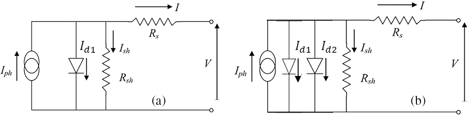
Figure 1: Equivalent circuit of a PV cell: (a) one-diode model, (b) two-diode model
The electrical current (I) of a photovoltaic (PV) panel in the two-diode model is typically expressed by the following equation:
The photocurrent Iph is linearly dependent on solar radiation, but is also influenced by temperature according to the following relationship:
where Gi is the solar irradiance on the module PV (in W/m2) and Gref is the reference irradiance. Under STC (Standard Test Conditions), the expression for Iph,ref is given by:
Through the utilization of the mesh law, the expression for the current Ish flowing through the shunt resistor can be derived as follows:
The diode current Idi is given by:
with [25]:
The thermal voltage of the module is given by
The current, I, supplied by the solar cell in the case of two-diode model is given by:
The electrical current, I, of the PV panel for the one-diode model is given by:
Fig. 2 illustrates the interaction between solar irradiation and tempered glass used as a protective cover for solar panels, in both cases, clean and with dust. When a PV panel is illuminated by incident light Gi, a part is reflected by Gr, another part is absorbed by Ga, and a third part is transmitted by Gt [26].
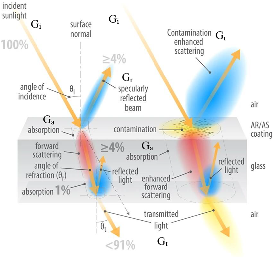
Figure 2: Light transmission by glass and its interaction with dust (based on [26]). Graphic: Al Hicks/NREL
According to the Bouguer-Lambert law [27], the theoretical transmittance,
The Ångström equation allows for the evaluation of the transmittance of a dust particle layer, providing insights into the extent of light attenuation caused by these particles. The decrease in transmittance arises from the interaction between dust particles and solar radiation, which is expounded upon by Mie’s theory. A modified Ångström turbidity equation (Eq. (11)) empirically characterizes the relative transmittance, and is expressed as follows [26,28]:
with:
a: Parameter related to the average particle size of dust [26,28–30].
b: Parameter related to the surface concentration of soiling [26,28–30].
λ: Wavelength of incident light (μm).
c: An offset constant (≈−0.01 to −0.25) that constitutes a component independent of the wavelength arising from the transmittance of very large particles that are unable to remain suspended in the air and consequently settle on the surface of the glass [26,28–30].
In the case of a soiled PV module,
On the other hand, the total transmittance is the product of the transmittance
So,
Then, for the case of high shunt and low series resistance, Eq. (4) in the presence of dust becomes:
Consequently, utilizing Eq. (2), the expression of for
Finally, the expression of the I-V characteristic of a PV cell in the case of one-diode model under the effect of a uniform amount of dust and exposed to sunlight is given by:
The expression of the I-V characteristic of a PV cell in the case of the two-diode model under the effect of a uniform amount of dust and exposed to sunlight is given by:
This article delves into a comprehensive analysis, combining theoretical insights and experimental findings, aimed at elucidating the I-V (current-voltage) characteristics of solar panels subjected to the deposition of dust particles. The I-V characteristic is a pivotal tool for assessing critical parameters, and its measurement is feasible under both illuminated and soiled conditions. Existing methodologies primarily rely on the I-V characteristic acquired under illuminated conditions. The mathematical equation governing the behavior of solar cells is contingent on the selected model for the solar cell.
3 Experimental Procedure and Methodology
To investigate the impact of soil accumulation on the electrical characteristics (I-V) of PV panels, two samples of dust were collected from the Agadir region of Morocco, specifically within the Souss-Massa plain [31]. The Agadir region, which serves as the administrative center of Souss Massa, is located on the southern Atlantic coastline of Morocco. Our research focused on a specific geographical area characterized by 30°25′ north latitude, 9°36′ west longitude. Dust samples used in our study were collected from two distinct locations within the Souss-Massa plain: Halieutic-Park HP (30°24′48.4″ N, 9°24′04.5″ W), and Adrar (AD) (30°25′37.6″ N, 9°32′24.1″ W) [31].
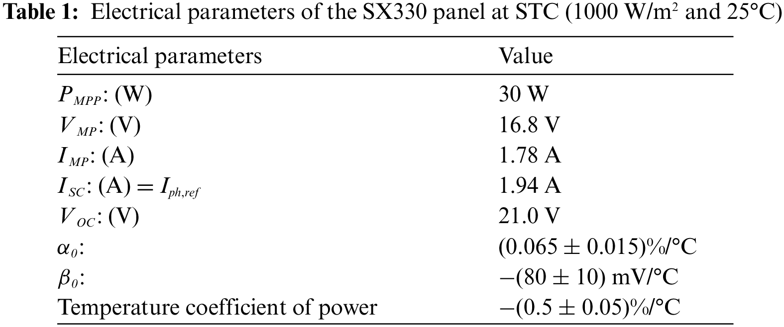
Fig. 3 presents the experimental procedure: upon collection, the dust underwent sieving to obtain a fine powder with particle diameters smaller than 250 µm. Subsequently, these fine particles were applied to the surface of a solar module, specifically SX330J, serving as our test panel. The assessment of the impact of deposited dust on the panel involved the measurement of optical transmittance, T(λ), through glass samples coated with dust. To examine the evolution of optical transmittance over a range of 400 to 800 nm as a function of dust density, we used a JASCO V730 UV-Vis spectrophotometer. In this investigation, we employed tempered glass samples with a thickness of 2.4 mm. Table 1 provides an overview of the parameters of the PV module as specified by the manufacturer.
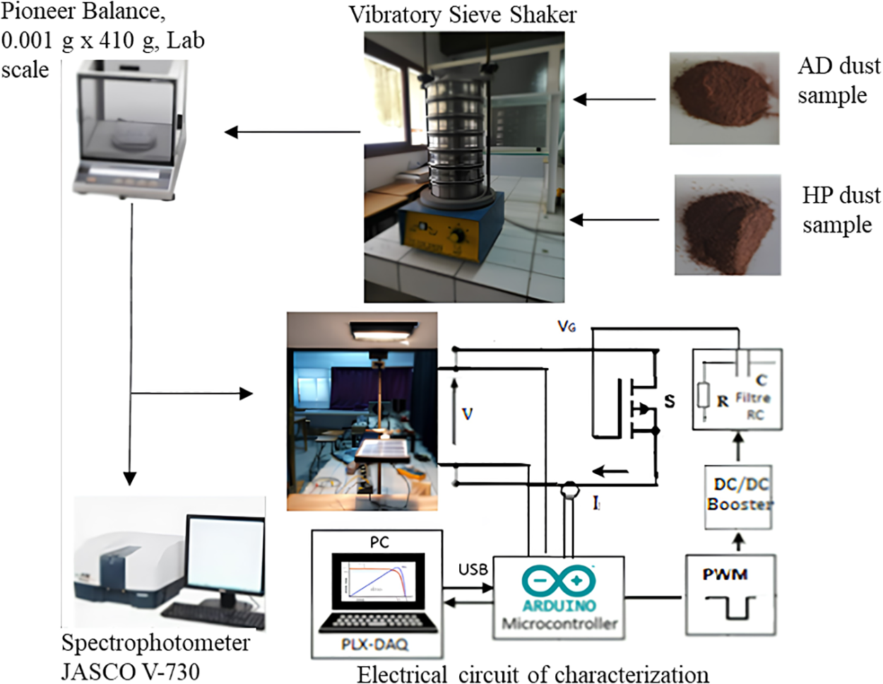
Figure 3: Test bench for the characterization of the soiling effect on a PV panel
Experimental measurements of current (I) and voltage (V) of SX330J PV panel were conducted using Arduino current and voltage sensors. The PV panel’s temperature was continuously monitored via a thermocouple, while irradiance levels were recorded using the FI 109SM solar meter.
Much attention has been paid to the accuracy of precision of the measurement equipment; the device developed for electrical data acquisition from the solar panel underwent a calibration procedure, which was based on DGM-360 multimeter tester [31]. This instrument boasts a voltage resolution of 0.01 V within the range of 60 to 4 V and a current intensity resolution of 0.001 A within the measurement range of 6 A. The manufacturer specifies an uncertainty of 0.02 % [31].
Extensive focus was directed toward ensuring the precision of the methods employed in this study. Spectral measurements for optical investigations were conducted repeatedly, demonstrating a high degree of reproducibility. For a more comprehensive description of the UV-Vis spectroscopy procedures, please refer to [31].
In this section, we carried out simulations with MATLAB/Simulink using the Newton-Raphson algorithm [15,32] to handle the complex nonlinear attributes of the I-V curve for the one-diode and two-diode models. Fig. 4 provides an illustrative depiction of the flowchart detailing the Newton-Raphson algorithm’s application in solving Eqs. (17) and (18).
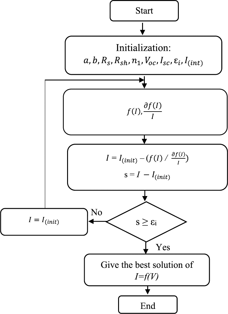
Figure 4: Flow chart of the Newton-Raphson algorithm used for this study
Our primary objective was to validate the models of Eqs. (17) or (18) by carrying out an in-depth comparison between our experimental and simulated results under temperature conditions of 25°C, 50°C and 60°C and for irradiances of 1 kW/m² and 820 W/m². As a simplification, the combined optical transmittance for the model is taken as
Fig. 5 shows the obtained results. In Figs. 5a and 5b, we can observe that at a low temperature of 25°C and irradiances of 1 and 820 W/m², the experimental results align with the double diode model. However, at high temperatures of 50°C and 60°C, which is the actual operating temperature of the solar panels, and at irradiances of 820 and 1 kW/m², we find that the experimental results are in line with the single-diode model simulation (Figs. 5c and 5d).
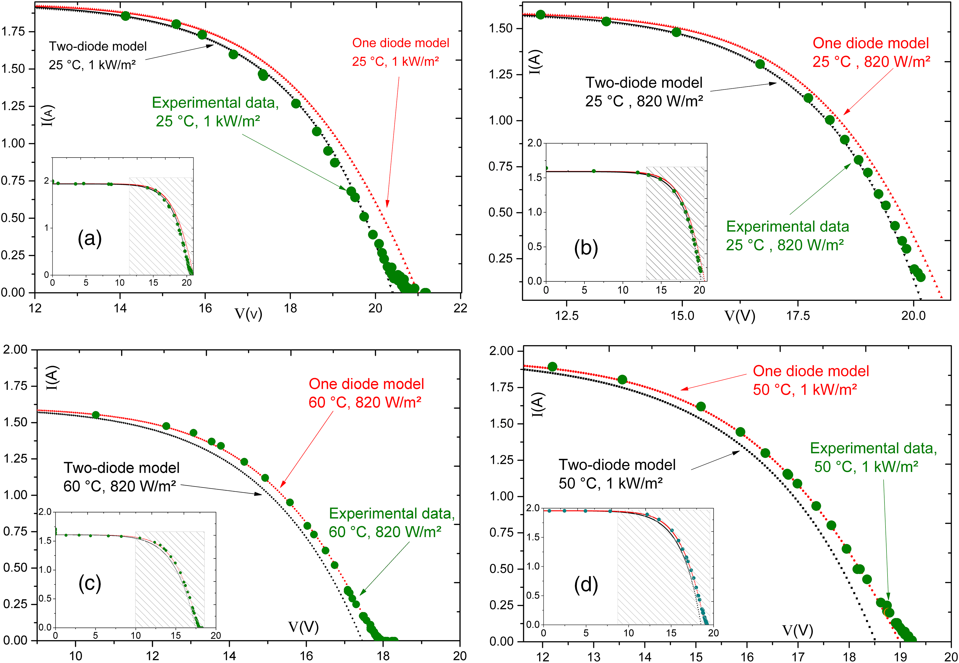
Figure 5: Simulated and experimental I-V characteristics of SX330J, (a) under conditions of 25°C and irradiances of 1 kW/m², and (b) under conditions of 25°C and irradiances of 820 W/m², (c) under conditions of 60°C and irradiances of 820 W/m², and (d) under conditions of 50°C and irradiances of 1 kW/m²
To provide a more lucid comprehension of these findings, we conducted tests and assessments on our SX330J PV panel under varying levels of illumination and temperatures. The insights drawn from these observations elucidate the following points:
- The single-diode model stands as the predominant choice, especially when conducting outdoor condition tests under the soiling effect [33].
- The single-diode model holds appeal as the simplest and most practical approach to constructing a solar cell model due to its capacity to effectively represent the PV characteristics of the majority of solar cells. Consequently, it finds wide applicability in numerous modeling scenarios, particularly when confronted with swiftly changing weather conditions [34,35].
- Under some conditions, the two-diode model emerges as the preferred option, delivering better performance compared to the single-diode model.
The one-diode model, known for its simplicity, is enhanced by the inclusion of a series resistor, Rs, to improve accuracy [4]. Nonetheless, despite its straightforwardness, this model exhibits significant relative errors when subjected to substantial temperature fluctuations. Consequently, to refine the accuracy of the one-diode model, the incorporation of a shunt resistance, Rsh, is introduced, albeit with a compromise in accuracy at low irradiance levels, particularly in the open-circuit voltage (VOC) range [5]. To further enhance the one-diode model’s fidelity, a second diode is introduced, giving rise to the two-diode model. This additional diode accounts for electron recombination both at the semiconductor material’s surface and within its volume [6].
4.1 Ts(λ) Optical Transmittance of Dust Samples
Regarding the dust samples collected from the site of Agadir-Morocco, Fig. 6 displays the reductions in Ts(λ) (expressed as a decimal) across different wavelengths. These experimental measurements were obtained using a JASCO V-730 spectrophotometer for dust samples collected from two distinct locations, namely AD and HP. The measurements are made relative to a clean piece of glass [26].
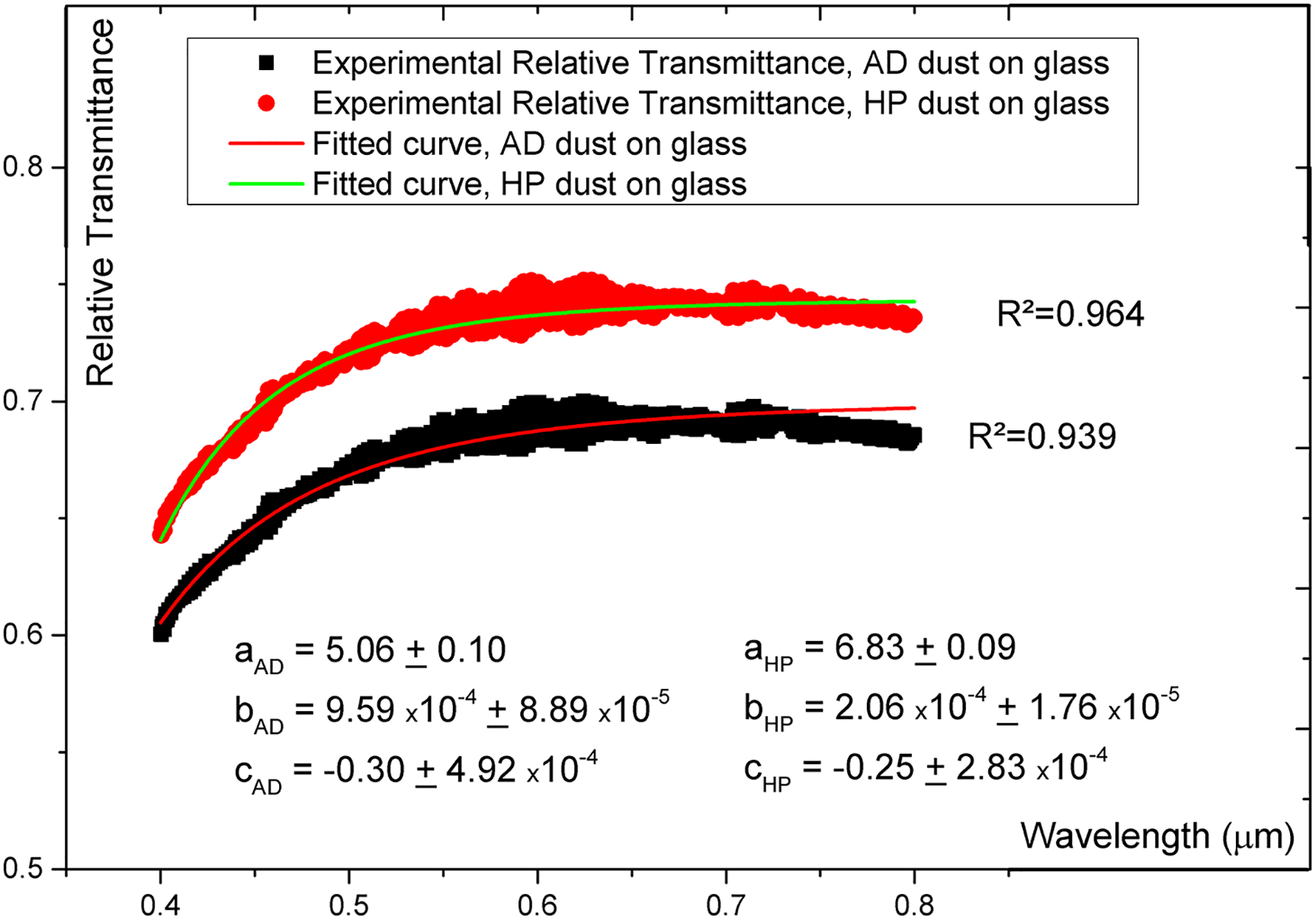
Figure 6: The relative optical transmittance of dust samples on glass
In this section, dust samples weighing 3.45 g/m² were collected from the two areas. It is worth noting that the soil composition in the Adrar area, AD, differs from that in the HP area. The outcomes of these tests highlight the influence of soiling on optical transmittance. A noticeable reduction in optical transmittance is evident, contingent upon the source of the dust. Since the transmittance due to soiling is essentially like a neutral density filter, changes in wavelength will likely have a minimal impact on the effect of soiling on the I-V characteristics of a PV panel. This is supported by the observations reported in our prior studies [26]. The exception is in the UV and blue portions of the spectrum.
4.2 Influence of Soiling on Solar Panel SX330J Performance
Throughout the subsequent simulations, the wavelength constant, a, was 5 to 7, while the other constants in the modified Ångström equation were approximately b = 2 to 10 × 10−4, and c = −0.25 to −0.3 [26]. The exact constants are given in Fig. 6. In the context of this investigation, the optimal wavelength (λ) for absorption corresponds to the wavelength at which the maximal spectral response is achieved. In our study, we used polycrystalline silicon (p-Si) type SX330J, which is the most widely used PV material, especially in our studied region, and has a relatively broad spectral response; it can efficiently convert photons with wavelengths ranging from 400 to 1200 nm. The response is highest in the visible light range and decreases toward the infrared range. We take the average wavelength at which the absorption efficiency is at a maximum value, in our case,
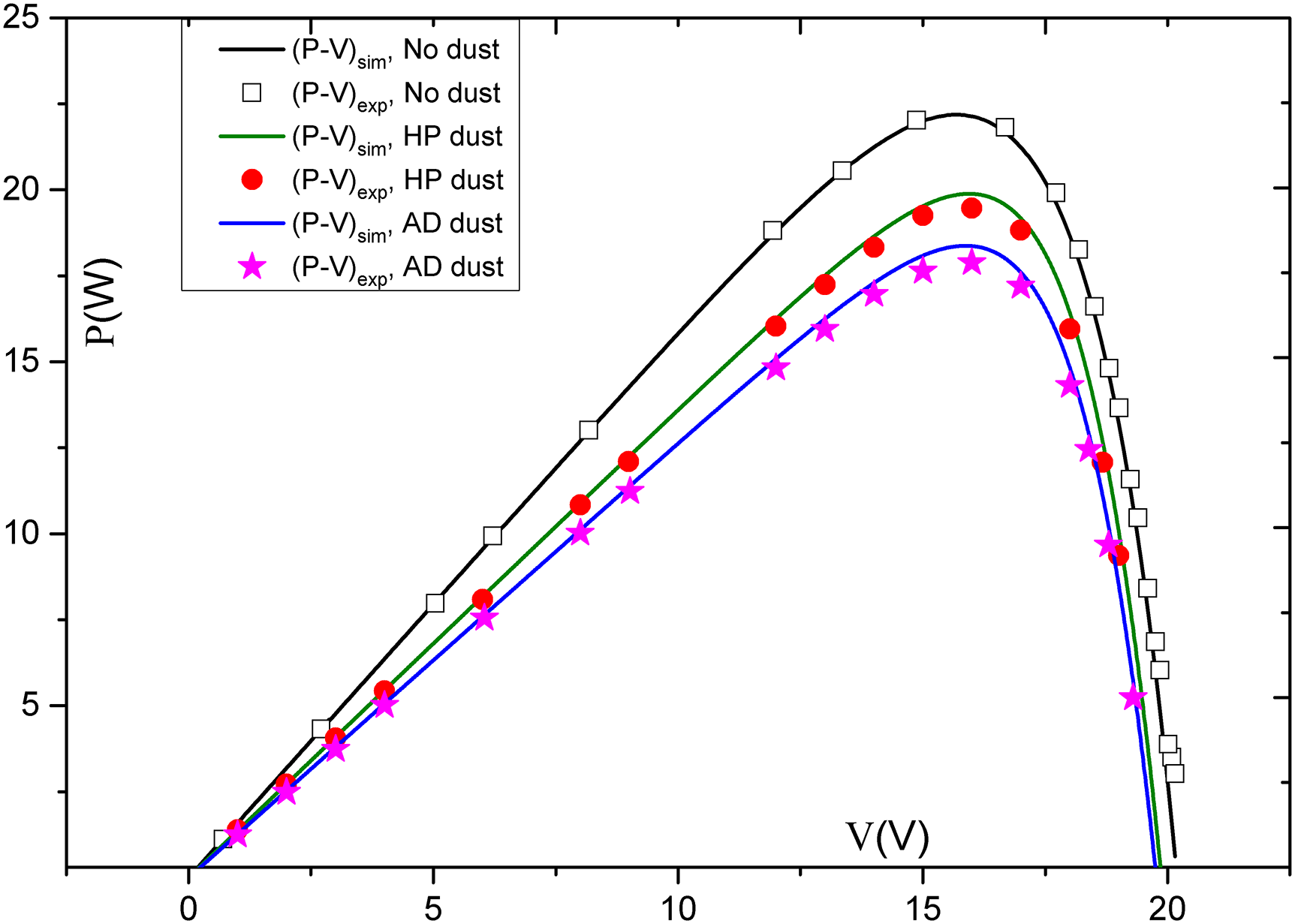
Figure 7: P-V characteristics of the SX-330J panel, simulated (sim) and experimental (exp) curves, at 25°C, G = 830 W/m², and under 3.45 g/m² of dust
Our research highlights a prominent finding, a noticeable decrease in the maximum power output (Fig. 8). The decline in Pmax = PMPP is not linear and exhibits a pronounced correlation with dust density. Our findings align well with previous studies conducted by various researchers [35–38].
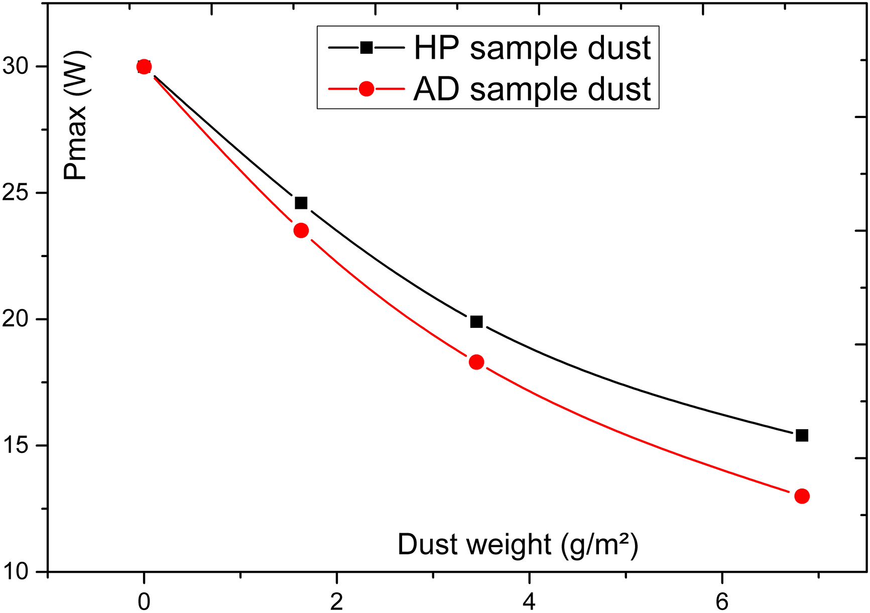
Figure 8: Experimental maximum power of the SX330J panel under the dust types of AD and HP samples
An important drop-off of PMPP (Pmax) is recorded upon soiling, depending on the density of dust. Our results are in good agreement with other reported works [35,39,40]. Specifically, when dealing with HP dust, our solar panel’s maximum power, PMPP, dwindles from 30 W to a mere 20 W at a dust density of approximately 3.45 g/m². In the case of AD dust, the decline is even more substantial, with Pmax dropping to a mere 17 W. This observed phenomenon can be attributed to the distinct distribution patterns of dust particles. Notably, the size distribution of dust particles significantly impacts the degradation of PV performance. Smaller particles can exhibit a greater capacity to obstruct and scatter sunlight radiation compared to larger particles. Consequently, they contribute significantly to the deterioration of PV performance, particularly at shorter wavelengths. This phenomenon is further exacerbated by the substantial loss in generated PV power, exceeding 45% in our study. Such a substantial power loss poses a critical source of uncertainty and risk in solar production. According to multiple authors, any loss exceeding 10% necessitates cleaning operations, which are indispensable for power recovery [35,41,42].
In this article, we introduced an innovative electro-optical model designed to quantify the impact of soiling on photovoltaic (PV) panels. Our model integrates Ångström’s optical transmittance principles with the I-V characteristic of the PV panel, offering a comprehensive insight into the effects of soiling. We investigated the consequences of using dust samples collected from distinct locations in Agadir, HP (Halieutic-Park) and AD (Adrar), on the electrical output of a polycrystalline PV panel, specifically the SX-330J model. This exploration yields valuable insights into how different types of dust impact PV panel performance. Furthermore, we note that the detrimental effects of dust accumulation are more pronounced in the Adrar (AD) region of Agadir than in the Halieutic Park (HP) area. These findings underscore the significance of regular cleaning maintenance for solar systems located in the AD region, emphasizing the critical need to mitigate the adverse impact of dust accumulation on PV panel performance. Future studies should explore the full range of the complexities of the model using the specific measured parameters for practical photovoltaic modules as input. They should also seek to determine the effects of series and parallel connections of the solar cells within a PV module on the overall performance and utility of the model.
Acknowledgement: The authors would like to thank and acknowledge the International Soiling Study members, and the Materials and Renewable Energies Laboratory, Université Ibn Zohr, Agadir, Morocco. The use of ChatGPT and Google Bard during the writing process is acknowledged, in accordance with Energy Engineering guidelines on Artificial Intelligence Generated Content. These tools have been employed under human supervision for improving spelling, grammar, clarity, and general editing.
Funding Statement: The authors received no specific funding for this study.
Author Contributions: The authors confirm contribution to the paper as follows: conceptualization, methodology, formal analysis, resources, investigation, writing–original draft, review & editing: A Asbayou and G. P. Smestad; formal analysis, resources, investigation, draft, writing–review, validation: L. Bouhouch; review: I. Isknan and A. Soussi; investigation study: A. Ihlal and A. Elfanaoui. All authors reviewed the results and approved the final version of the manuscript.
Availability of Data and Materials: The authors confirm that the data used in this study are available on request.
Conflicts of Interest: The authors declare that they have no conflicts of interest to report regarding the present study.
References
1. Singh, J., Kaur, R., Singh, D. (2021). Energy harvesting in wireless sensor networks: A taxonomic survey. International Journal of Energy Research, 45(1), 118–140. [Google Scholar]
2. Sayyad, J., Nasikkar, P. (2021). Design and development of low cost, portable, on-field IV curve tracer based on capacitor loading for high power rated solar photovoltaic modules. IEEE Access, 9, 70715–70731. [Google Scholar]
3. Ciulla, G., Brano, V. L., di Dio, V., Cipriani, G. (2014). A comparison of different one-diode models for the representation of I-V characteristic of a PV cell. Renewable and Sustainable Energy Reviews, 32, 684–696. [Google Scholar]
4. Asbayou, A., Aamoume, A., Elyaqouti, M., Ihlal, A., Bouhouch, L. (2022). Benchmarking study between capacitive and electronic load technic to track IV and PV of a solar panel. International Journal of Electrical and Computer Engineering, 12(1), 102–113. [Google Scholar]
5. Kumar, C., Mary, D. M. (2022). A novel chaotic-driven tuna swarm optimizer with Newton-Raphson method for parameter identification of three-diode equivalent circuit model of solar photovoltaiccells/modules. Optik, 264, 169379. [Google Scholar]
6. Brinkman, W. F., Rice, T. M. (1973). Electron-hole liquids in semiconductors. Physical Review B, 7(4), 1508. [Google Scholar]
7. Lappalainen, K., Piliougine, M., Valkealahti, S., Spagnuolo, G. (2023). Photovoltaic module series resistance identification at its maximum power production. Mathematics and Computers in Simulation, 218, 1–13. https://doi.org/10.1016/j.matcom.2023.05.021 [Google Scholar] [CrossRef]
8. Al-Dousari, A., Al-Nassar, W., Al-Hemoud, A., Alsaleh, A., Ramadan, A. et al. (2019). Solar and wind energy: Challenges and solutions in desert regions. Energy, 176, 184–194. https://doi.org/10.1016/j.energy.2019.03.180 [Google Scholar] [CrossRef]
9. Zarei, T., Abdolzadeh, M. (2016). Optical and thermal modeling of a tilted photovoltaic module with sand particles settled on its front surface. Energy, 95, 51–66. https://doi.org/10.1016/j.energy.2015.11.045 [Google Scholar] [CrossRef]
10. Sarver, T., Al-Qaraghuli, A., Kazmerski, L. L. (2013). A comprehensive review of the impact of dust on the use of solar energy: History, investigations, results, literature, and mitigation approaches. Renewable and Sustainable Energy Reviews, 22, 698–733. https://doi.org/10.1016/j.rser.2012.12.065 [Google Scholar] [CrossRef]
11. Costa, S., Diniz, A. C., Kazmerski, L. L. (2016). Dust and soiling issues and impacts relating to solar energy systems: Literature review update for 2012–2015. Renewable and Sustainable Energy Reviews, 63, 33–61. https://doi.org/10.1016/j.rser.2016.04.059 [Google Scholar] [CrossRef]
12. Adinoyi, M. J., Said, S. A. M. (2013). Effect of dust accumulation on the power outputs of solar photovoltaic modules. Renewable Energy, 60, 633–636. https://doi.org/10.1016/j.renene.2013.06.014 [Google Scholar] [CrossRef]
13. Zorrilla-Casanova, M., Piliougine, J., Carretero, M., Bernaola, J., Carpena, P. et al. (2012). Analysis of dust losses in photovoltaic modules. Word Renewable Energy Congress, pp. 2985–2992. Linköping, Sweden. [Google Scholar]
14. Alsafasfeh, Q. (2020). An efficient algorithm for power prediction in PV generation system. International Journal of Renewable Energy Development, 9(2), 207–216. [Google Scholar]
15. Rasheed, M., Shihab, S., Rashid, T. (2021). Two Step and Newton-Raphson algorithms in the extraction for the parameters of solar cell. Al-Qadisiyah Journal of Pure Science, 26(1), 143–154. [Google Scholar]
16. Zhu, Y., Xiao, W. (2020). A comprehensive review of topologies for photovoltaic I-V curve tracer. Solar Energy, 196, 346–357. [Google Scholar]
17. Sarikh, S., Raoufi, M., Bennouna, A., Benlarabi, A., Ikken, B. (2020). Implementation of a plug and play I-V curve tracer dedicated to characterization and diagnosis of PV modules under real operating conditions. Energy Conversion and Management, 209, 112613. [Google Scholar]
18. Yadir, S., Bendaoud, R., EL-Abidi, A., Amiry, H., Benhmida, M. et al. (2020). Evolution of the physical parameters of photovoltaic generators as a function of temperature and irradiance: New method of prediction based on the manufacturer’s datasheet. Energy Conversion and Management, 203, 112141. [Google Scholar]
19. Spertino, F., Ahmad, J., Ciocia, A. D. P., Murtaza, A. F. et al. (2015). Capacitor charging method for I-V curve tracer and MPPT in photovoltaic systems. Solar Energy, 119, 461–473. [Google Scholar]
20. Cotfas, D. T., Cotfas, P. A., Ursutiu, D., Samoila, C. (2010). Current-voltage characteristic raising techniques for solar cells. 12th International Conference on Optimization of Electrical and Electronic Equipment, pp. 1115–1120. Brasov, Romania. [Google Scholar]
21. Chen, Z., Lin, W., Wu, L., Long, C., Lin, P. et al. (2018). A capacitor based fast I-V characteristics tester for photovoltaic arrays. Energy Procedia, 145, 381–387. [Google Scholar]
22. Li, H., Hu, Y., Wang, H., Tao, Q., Zhu, Y. et al. (2021). Full-spectrum absorption enhancement in a-Si: H thin-film solar cell with a composite light-trapping structure. Solar RRL, 5(3), 2000524. [Google Scholar]
23. Soon, J. J., Goh, S. T., Maneuver, N. (2014). Multi-dimension diode photovoltaic model for different PV cell technologies. 2014 IEEE 23rd International Symposium on Industrial Electronics (ISIE), pp. 2496–2501. Istanbul, Turkey. https://doi.org/10.1109/ISIE.2014.6865012 [Google Scholar] [CrossRef]
24. Rashel, M. R., Albino, A., Veiga, A., Ahmed, M. T., Tlemcani, M. et al. (2017). Comparison of Photovoltaic panel’s standard and simplified models. 2016 International Conference for Students on Applied Engineering (ICSAE), pp. 133–136. Newcastle Upon Tyne, UK. https://doi.org/10.1109/ICSAE.2016.7810175 [Google Scholar] [CrossRef]
25. Ma, X., Bader, S., Oelmann, B. (2021). On the performance of the two-diode model for photovoltaic cells under indoor artificial lighting. IEEE Access, 9, 1350–1361. https://doi.org/10.1109/ACCESS.2020.3047158 [Google Scholar] [CrossRef]
26. Smestad, G. P., Germer, T. A., Alrashidi, H., Fernández, E. F., Dey, S. et al. (2020). Modelling photovoltaic soiling losses through optical characterization. Scientific Reports, 10(1), 1–13. [Google Scholar]
27. Mayerhöfer, T. G., Pahlow, S., Popp, J. (2020). The Bouguer-Beer-Lambert Law: Shining light on the obscure. ChemPhysChem, 21(18), 2029–2046. https://doi.org/10.1002/cphc.202000464 [Google Scholar] [PubMed] [CrossRef]
28. Salmon, A., Quiñones, G., Soto, G., Polo, J., Gueymard, C. et al. (2021). Advances in aerosol optical depth evaluation from broadband direct normal irradiance measurements. Solar Energy, 221, 206–217. [Google Scholar]
29. Salazar, G., Utrillas, P., Esteve, A., Lozano, J. M., Aristizabal, M. (2013). Estimation of daily average values of the Ångström turbidity coefficient β using a Corrected Yang Hybrid Model. Renewable Energy, 51, 182–188. [Google Scholar]
30. Eltbaakh, Y. A., Ruslan, M. H., Alghoul, M. A., Othman, M. Y., Sopian, K. (2012). Issues concerning atmospheric turbidity indices. Renewable and Sustainable Energy Reviews, 16(8), 6285–6294. [Google Scholar]
31. Asbayou, A., Ihlal, A., Isknan, I., Soussi, A., Bouhouch, L. (2023). Structural and physicochemical properties of dust and their effect on solar modules efficiency in Agadir-Morocco. Journal of Renewable Materials, 11(5), 2249–2264. https://doi.org/10.32604/jrm.2023.025456 [Google Scholar] [CrossRef]
32. Humada, A. M., Hojabri, M., Mekhilef, S., Hamada, H. M. (2016). Solar cell parameters extraction based on single and double-diode models: A review. Renewable and Sustainable Energy Reviews, 56, 494–509. https://doi.org/10.1016/j.rser.2015.11.051 [Google Scholar] [CrossRef]
33. Gholami, A., Ameri, M., Zandi, M., Gavagsaz Ghoachani, R. (2021). A single-diode model for photovoltaic panels in variable environmental conditions: Investigating dust impacts with experimental evaluation. Sustainable Energy Technologies and Assessments, 47, 101392. https://doi.org/10.1016/j.seta.2021.101392 [Google Scholar] [CrossRef]
34. Kazem, H. A., Al-Waeli, A. H., Chaichan, M. T., Sopian, K. (2022). Modeling and experimental validation of dust impact on solar cell performance. Energy Sources, Part A: Recovery, Utilization, and Environmental Effects, 1–17. https://doi.org/10.1080/15567036.2021.2024922 [Google Scholar] [CrossRef]
35. Azouzoute, A., Hajjaj, C., Zitouni, H., El Ydrissi, M., Mertah, O. et al. (2021). Modeling and experimental investigation of dust effect on glass cover PV module with fixed and tracking system under semi-arid climate. Solar Energy Materials and Solar Cells, 230, 111219. [Google Scholar]
36. Salamah, T., Ramahi, A., Alamara, K., Juaidi, A., Abdallah, R. et al. (2022). Effect of dust and methods of cleaning on the performance of solar PV module for different climate regions: Comprehensive review. Science of the Total Environment, 827, 154050. [Google Scholar] [PubMed]
37. Asl-Soleimani, E., Farhangi, S., Zabihi, M. S. (2001). The effect of tilt angle, air pollution on performance of photovoltaic systems in Tehran. Renewable Energy, 24(3–4), 459–468. [Google Scholar]
38. Kaldellis, J. K., Zafirakis, D., Kondili, E. (2010). Optimum sizing of photovoltaic-energy storage systems for autonomous small islands. International Journal of Electrical Power & Energy Systems, 32(1), 24–36. [Google Scholar]
39. Fan, S., Wang, Y., Cao, S., Sun, T., Liu, P. (2021). A novel method for analyzing the effect of dust accumulation on energy efficiency loss in photovoltaic (PV) system. Energy, 234, 121112. [Google Scholar]
40. He, B., Lu, H., Zheng, C., Wang, Y. (2023). Characteristics and cleaning methods of dust deposition on solar photovoltaic modules–A review. Energy, 263, 126083. [Google Scholar]
41. Al-Sulaiman, A. F., Dincer, I., Hamdullahpur, F. (2011). Exergy modeling of a new solar driven trigeneration system. Solar Energy, 85(9), 2228–2243. [Google Scholar]
42. Adıgüzel, E., Subaşı, N., Mumcu, T. V., Ersoy, A. (2023). The effect of the marble dust to the efficiency of photovoltaic panels efficiency by SVM. Energy Reports, 9, 66–76. [Google Scholar]
Cite This Article
 Copyright © 2024 The Author(s). Published by Tech Science Press.
This work is licensed under a Creative Commons Attribution 4.0 International License , which permits unrestricted use, distribution, and reproduction in any medium, provided the original work is properly cited.
 Downloads
 Citation Tools