
 Submit a Paper
 Propose a Special lssue
 Open Access
ARTICLE

Parasitic Shunt Currents in Alkaline Water Electrolysis (AWE) for Generating Clean Hydrogen
1 Faculty of Mechanical Engineering, University of Tabriz, Tabriz, 51664, Iran
2 Faculty of Mechanical Engineering, University of Mohaghegh Ardabili, Ardabil, 56199, Iran
* Corresponding Author: Seyyed Kazem Yekani. Email:
(This article belongs to the Special Issue: Green Hydrogen Technologies)
Energy Engineering 2025, 122(10), 4121-4134. https://doi.org/10.32604/ee.2025.067446
Received 04 May 2025; Accepted 02 July 2025; Issue published 30 September 2025
 View Full Text
 Download PDF
Abstract
Since the beginning of the 20th century, alkaline electrolysis has been used as a proven method for producing hydrogen on a megawatt scale. The existence of parasitic shunt currents in alkaline water electrolysis, which is utilized to produce clean hydrogen, is investigated in this work. Analysis has been done on a 20-cell stack. Steel end plates, bipolar plates, and an electrolyte concentration of 6 M potassium hydroxide are all included in the model. The Butler-Volmer kinetics equations are used to simulate the electrode surfaces. Ohmic losses are taken into consideration in both the electrode and electrolyte phases, although mass transport constraints in the gas phase are not. Using an auxiliary sweep to solve equations, the model maintains an isothermal condition at 85°C while adjusting the average cell voltage between 1.3 and 1.8 V. The results show that lower shunt currents in the outlet channels as opposed to the intake channels are the result of the electrolyte’s lower effective conductivity in the upper channels, which is brought on by a lower volume fraction of the electrolyte. Additionally, it has been seen that the shunt currents intensify as the stack gets closer to the conclusion. Efficiency is calculated by dividing the maximum energy output (per unit of time) that a fuel cell operating under comparable conditions might produce by the electrical energy needed to generate that output inside the stack. At first, energy efficiency increases due to the rise in coulombic efficiency, peaking around 1400 mA. The subsequent decline after reaching 1400 mA is linked to an increase in stack voltage at elevated current levels.Keywords
Globally, suggested remedies concentrate on generating and storing renewable energy. In this context, hydrogen production has become significant among energy storage techniques due to its energy density, substantial energy capacity, and ability to be transported [1,2].
Alkaline water electrolysis (AWE) is a technique that employs electrical energy to split water into hydrogen and oxygen gases using an alkaline electrolyte, typically potassium hydroxide (KOH). Two electrodes are usually used in the process: the anode produces oxygen, while the cathode produces hydrogen. The most widely used technique for electrolytic hydrogen production is alkaline electrolyzers, which are acknowledged for their high level of industrial maturity. These electrolyzers usually operate at current densities below 0.5 A/cm2. They are designed for robustness and cost-effectiveness. They are considered reliable and efficient, with many units deployed in various industrial applications. Alkaline electrolysis contributes significantly to green hydrogen production, aligning with modern sustainability goals. This technology is gaining attention for large-scale hydrogen production due to its potential environmental benefits. Ongoing research focuses on enhancing the efficiency and reducing costs of alkaline electrolyzers, including improvements in electrode materials and system design.
Numerous reviews exist that outline the various technologies associated with hydrogen utilization. In their exhaustive analysis and comparison of current storage methods, Abdalla et al. [3] provide a thorough overview of hydrogen technologies. Zhang et al. [4] provide a clear and well-structured summary of production, storage, and electricity-producing systems. In addition to describing the generation, storage, and use of hydrogen, Dutta [5] provides development proposals for the hydrogen economy in several countries. The economic aspects of both centralized and decentralized production techniques are examined by Mazloomi and Gomes [6]. Additionally, they discuss the hazards associated with the production, storage, and distribution phases and offer viable risk-reduction techniques. At the same time, research such as [7] describes the procedures required to develop a hydrogen economy. Power-to-gas [8,9], using fossil hydrogen to power vehicles [10–13], and connecting electrolyzers to renewable energy sources in microgrids [14,15] are some of these measures. According to Wong and Afrouzi [16], one of the newest green technologies is the hydrogen energy storage system (HESS), which uses excess energy to create hydrogen and store it for later use. To improve a HESS design, it is crucial to understand optimal design techniques because navigating the design and sizing processes can be intimidating, given the abundance of information accessible. Therefore, they intended to gather and analyze a broad spectrum of HESS studies to provide a summary of recent research findings. Through an analysis of the mathematical structure governing wind power output and the evaluation of the remaining wind energy, along with the functionalities of hydrogen production and storage using electrolyzers and hydrogen storage tanks, Lu et al. [17] developed a capacity optimization allocation model for hydrogen production systems. The objective of their model was to minimize the total net present value cost across the entire lifecycle, incorporating a cost-benefit analysis that included costs for equipment disposal, recovery of residual value, penalties associated with wind energy curtailment, transportation costs for hydrogen, and environmental considerations. The model was implemented on the MATLAB platform, leveraging the CPLEX solver for its resolution. Zhang et al. [18] formulated an evaluation index system to assess the suitability of hydrogen production and hydrogenation stations, concentrating on four primary factors: technology, economy, environment, and safety. By taking real-world conditions into account, they utilized the Analytic Hierarchy Process (AHP) and Fuzzy Comprehensive evaluation methods to evaluate hydrogen production and hydrogenation utilizing both water electrolysis and natural gas reforming. Their results demonstrated that hydrogen production through water electrolysis was superior to that from natural gas reforming in the context of hydrogen production and hydrogenation stations, rendering it the more favorable choice. Furthermore, although natural gas reforming outperformed water electrolysis economically for hydrogen production, it lagged in technological efficiency, environmental impact, and safety. Wang et al. [19] pointed out that the uncertainty in renewable energy generation combined with the fluctuation in load demand presents difficulties in determining the capacity of each component in hybrid renewable energy power generation systems. Their study concentrated on optimizing the capacity of two configurations of the off-grid hybrid wind-hydrogen energy system. To achieve their optimization goals, they aimed to maximize system profitability while minimizing the chances of a power supply failure. Initially, they developed steady-state models for the wind turbine, proton exchange membrane fuel cell, lead-acid battery, and alkaline electrolyzer using MATLAB software. They subsequently examined the operating modes of the system and uncovered two distinct setups. Eventually, they evaluated the economic aspects of both systems and chose the optimal configuration based on the wind speed and load data specific to the sample area. The performance of alkaline water electrolysis systems is commonly restricted by several factors, including reaction overpotentials and the durability of the electrocatalysts. Recent reviews have emphasized the importance of optimizing each component within the hydrogen production system to improve operational efficiency [20,21]. Recent studies have suggested the use of bipolar membranes to enhance the efficiency of water electrolysis. These membranes create a bridge between acidic and alkaline environments, potentially improving the overall electrolysis performance [22]. The correlation between water dissociation activity and HER activity presents a significant area for further exploration. Moreover, the development of novel hybrid nanoarray structures has demonstrated superior performance for both HER and OER, indicating that interface engineering can play a crucial role in enhancing catalytic activity [23].
A digital twin-based predictive maintenance method for alkaline water electrolysis systems, improving fault diagnosis and lifespan prediction by combining simulation models, deep learning algorithms, and transfer learning has been reported. It achieves higher accuracy and reliability, enhancing system monitoring and fault detection during operation [24]. A semi-empirical model of an alkaline water electrolyzer, accurately capturing cell voltage behavior using polarization data has been performed. It also analyzes how operational factors impact efficiency, providing insights to optimize AWE performance [25]. Traditionally, AWE uses diaphragms and 5–7 M KOH, but polymeric diaphragms replaced asbestos ones. Newer alternatives include ion-solvating membranes and high-conductivity membranes in 1 M KOH. AEM systems with 0–1 M KOH have improved lifespan and electrode issues. As AWE and AEM technologies converge, this review highlights recent developments in these membranes [26]. Alkaline electrolysis is well-established on land, but its economic performance at sea is less understood. Sea-sourced purified water varies in cost and impurities can reduce efficiency, leading to higher electricity costs. Different electrolyte management options also affect costs. This article explores the economic viability of offshore alkaline electrolysis, highlighting knowledge gaps and encouraging discussion in the field [27].
While considering the crucial economic considerations for long-term sustainability, all of these developments take hydrogen technologies into account. Collaboration between businesses, governments, and research institutions will be necessary to accomplish this. Alongside the technologies, Fig. 1 presents the options, which include both established industrial techniques and those currently under development.
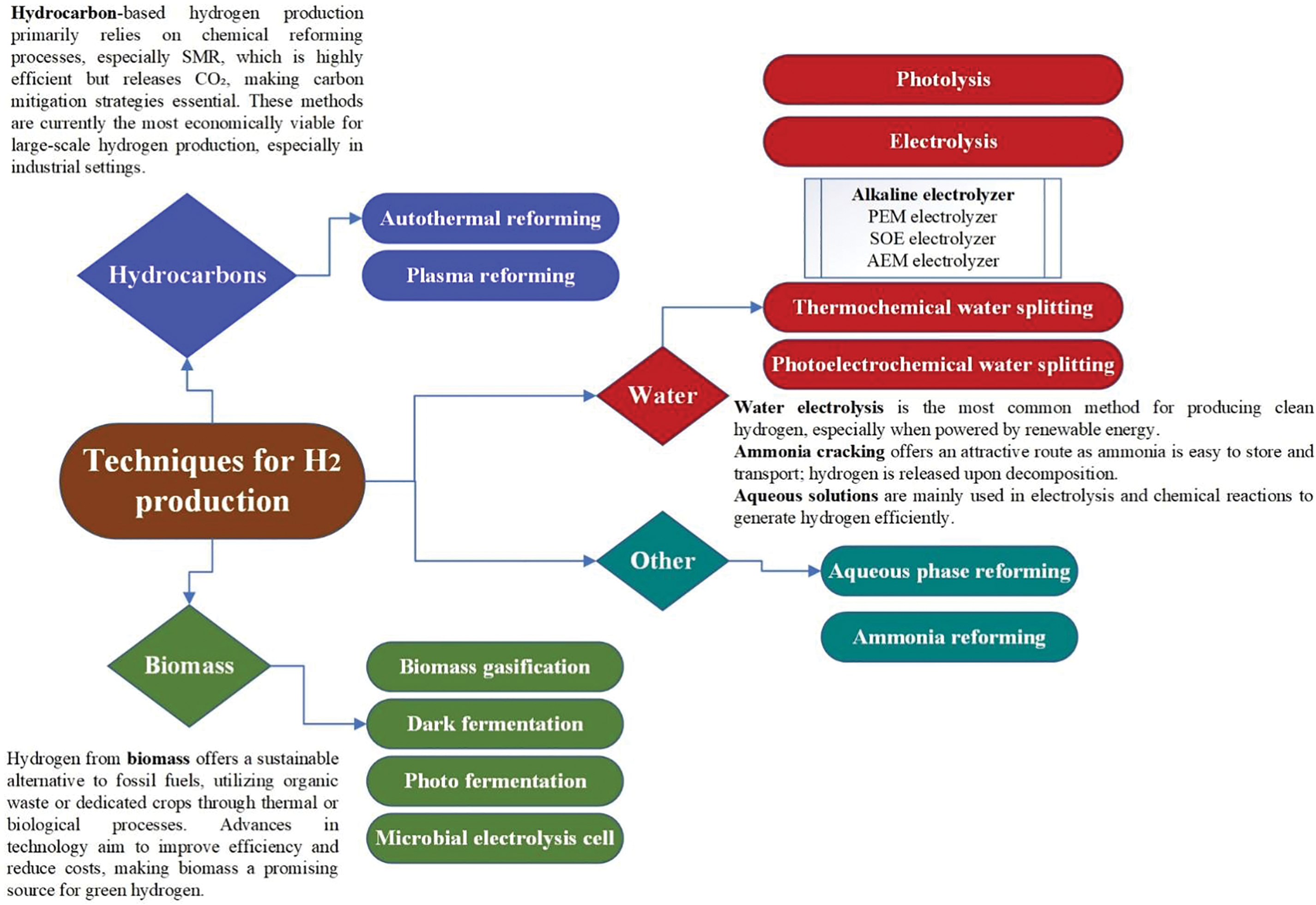
Figure 1: Classification of hydrogen production focusing on the objective of this paper [28]
To reduce the expenses associated with hydrogen production, it is crucial to operate the electrolyzers as efficiently as possible and to ensure their prolonged operational lifespan. The existence of parasitic shunt currents is one element that limits the stack’s longevity and efficiency. This paper illustrates a secondary current distribution in a 20-cell setup. The coulombic and energy efficiencies for the stack, relating to electricity-to-hydrogen conversion, are calculated, along with the specific shunt currents flowing into or out of each cell. This work contributes new understanding of how electrolyte management and current operations affect efficiency and parasitic losses in alkaline electrolysis stacks.
The main components of the AWE system covered in this paper are a stack, two gas-liquid oxygen and hydrogen separators, an electrolyte pump, a heat exchanger, and a water tank. It also has other electrical components and purifying devices, which are not discussed here. A direct electrical current drives an electrochemical reaction in the stack’s electrolyte while the AWE system is operating. Hydrogen gas and OH− ions are produced at the cathode when water molecules in the electrolyte get electrons and go through a hydrogen evolution reduction process. In addition to the influence of the electric field, the concentration gradient between the cathode and anode sides causes the OH− ions to migrate through the membrane. Water and oxygen gas are produced on the anode side when OH− ions undergo an oxygen evolution oxidation process and lose electrons. After leaving the stack, the produced combination of oxygen gas and electrolyte and hydrogen gas and electrolyte enters the two separators. As the electrolyte is brought back to the mixer for remixing, the gases leave the system. To maintain the temperature of the stack, the pump first presses the electrolyte out of the mixer, which is subsequently cooled by cooling water in a heat exchanger. The AWE system is illustrated in Fig. 2. This research examines the 20-cell stack depicted in Fig. 3. This type includes a 6 M potassium hydroxide (KOH) electrolyte [26], bipolar plates, and steel end plates. The Butler-Volmer kinetics equations are used to represent the electrode surfaces. Mass transport restrictions in the gas phase are disregarded, while ohmic losses in the electrode and electrolyte phases are taken into consideration. The equations are solved using an auxiliary sweep, changing the average cell voltage from 1.3 to 1.8 V, and the model runs isothermally at 85°C. Two separate half-cell reactions are involved in the electrochemical process of water splitting: the oxygen evolution reaction at the anode and the hydrogen evolution reaction at the cathode [29].
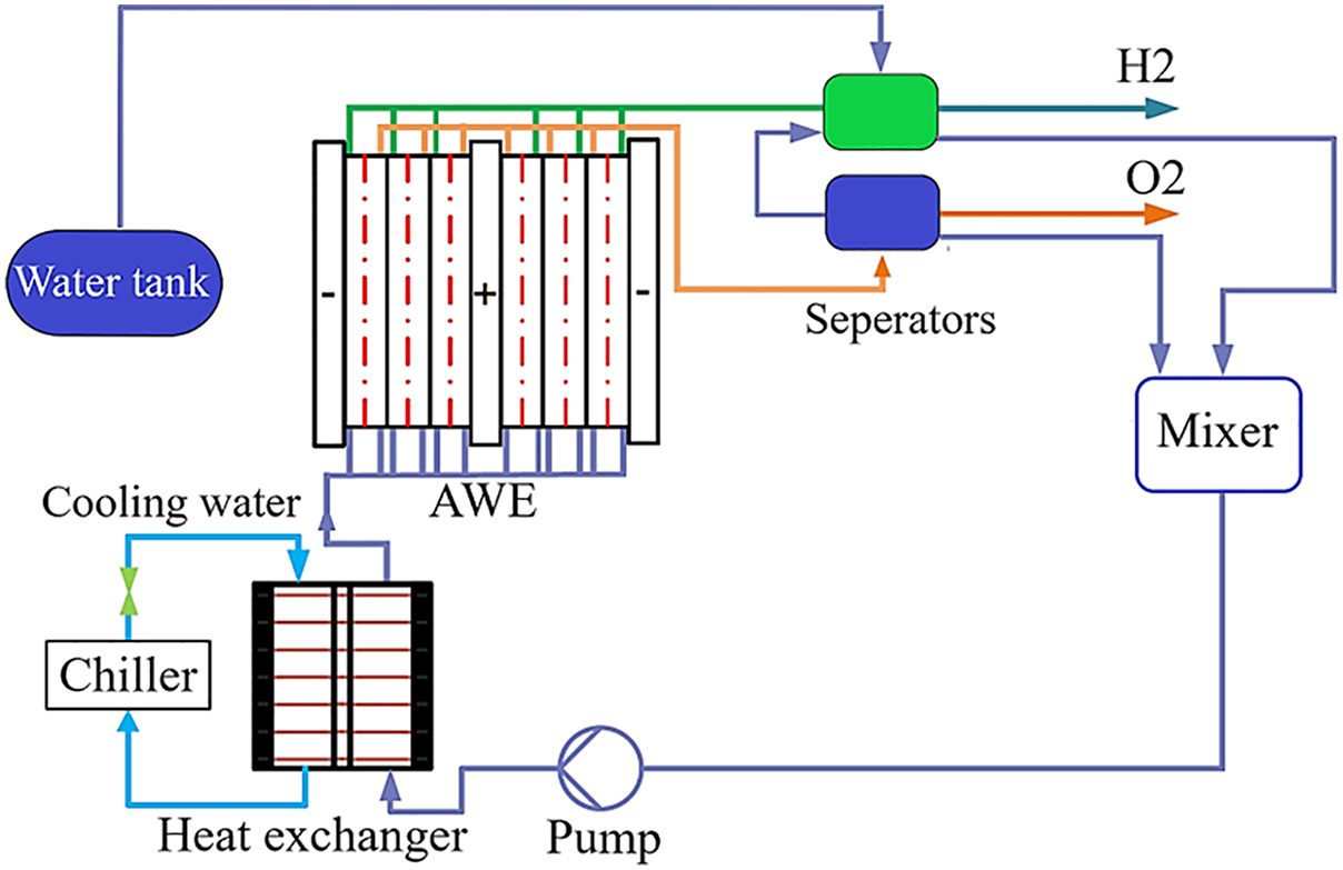
Figure 2: Illustration of the AWE system
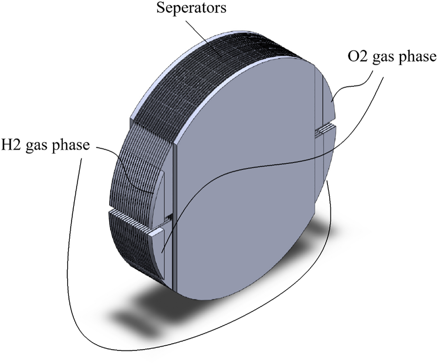
Figure 3: Modeled AWE
Shunt currents can have several important consequences:
• Decreased Efficiency: They lead to unwanted energy losses, lowering the overall performance of devices such as fuel cells or electrochemical cells.
• Irregular Current Distribution: Shunt currents may result in uneven current flow throughout individual cells or components, which can create localized overpotentials and lead to degradation.
• Damage to Components: Continuous shunt currents might hasten the deterioration or damage of electrodes and other system components due to inconsistent electrochemical activity.
• Challenges in Measurement: They create difficulties in measuring voltage and current, hindering system diagnostics and evaluations of performance.
• Instabilities in Operation: Excessive shunt currents can disrupt system stability, resulting in unpredictable behavior or safety issues.
In electrochemical systems, shunt currents are generated at reaction sites, as explained in the context of the Butler-Volmer equation, which models the relationship between current and voltage at an electrode. In some situations, such as in a stack without any load, the equation predicts a non-zero current, which results in shunt currents. These shunt currents are driven by electrochemical reactions at the electrode surfaces and are influenced by variables such as the voltage difference and ohmic losses in the system. The Butler-Volmer equation plays a crucial role in determining shunt currents by outlining the kinetics of electrochemical reactions at the electrode. It essentially connects the current density to the overpotential, taking into account both the forward (oxidation) and reverse (reduction) reactions. When this equation is applied to systems with shunt paths—such as in multi-cell stacks or fuel cells—it forecasts the amount of current that can travel through unintended or parallel routes at each electrode. In more straightforward terms, if the potential difference across a shunt path causes the overpotential to exceed a specific threshold, the Butler-Volmer equation estimates the resulting current flow through that path. This phenomenon can result in parasitic or undesired currents (shunt currents) that circumvent the main circuit, impacting the efficiency and performance of the system.
Various elements affect shunt currents in systems represented by the Butler-Volmer equation:
• Voltage difference (overpotential): The extent of the voltage difference across shunt pathways drives current flow. Greater overpotentials elevate shunt currents.
• Electrode kinetics (exchange current density): More rapid reaction kinetics (higher exchange current density) facilitate current flow through shunt pathways at a specific overpotential.
• Electrolyte conductivity: Improved conductivity lowers the ohmic resistance along shunt pathways, enabling more current to pass through.
• Shunt pathway resistance: The inherent resistance or impedance of unintended current paths dictates how much current can flow for a specified voltage.
• Reaction conditions: Factors such as temperature, catalyst effectiveness, and surface characteristics impact reaction rates, thereby influencing shunt currents.
• System design: The arrangement and configuration of the cell stack, including the positioning of membranes and electrodes, affect shunt pathways.
Herein, Butler-Volmer kinetics is used to simulate the electrode surfaces, accounting for both ohmic losses in the electrodes and electrolyte phases while ignoring any effects from gas-phase mass transport restrictions (this is known as a secondary current distribution model). The model operates under isothermal conditions, with the stack functioning at a temperature of 85°C. The effective conductivity of the electrolyte within the electrolyte compartment on either side of the separator is established to vary based on the volume fraction of the electrolyte according to:
In this context,
The principle of mass conservation was articulated through the continuity equation within all computational domains, as stated below:
where u represents the velocity vector of the electrolyte.
The flow channels had their velocity field defined by the Navier-Stokes equation [30]:
In this context, ρ refers to the density of the electrolyte.
The velocity distribution within the porous electrodes was determined by integrating the Navier-Stokes equation with Darcy’s law for porous media, leading to the results in [31–33]:
where κ represents the permeability of the porous electrode and ε denotes its porosity.
Fig. 4 represents streamlines for various voltage differences. The shunt current patterns depicted in Fig. 4 can be calculated by integrating the internal boundary between each manifold and its corresponding electrolyte compartment to determine the specific entry and exit shunt currents for each cell. This is illustrated in Figs. 5–7 for average cell voltages. Fig. 5 represents electrolyte potential. Electrolyte Potential pertains to the electric potential present in an electrolyte solution, a conductive liquid that contains ions. It is vital in electrochemical systems, including electrolysis processes, where the movement of ions produces an electric current. It shows how voltage fluctuates within the electrolyte and influences ion transport and the overall performance of the device.
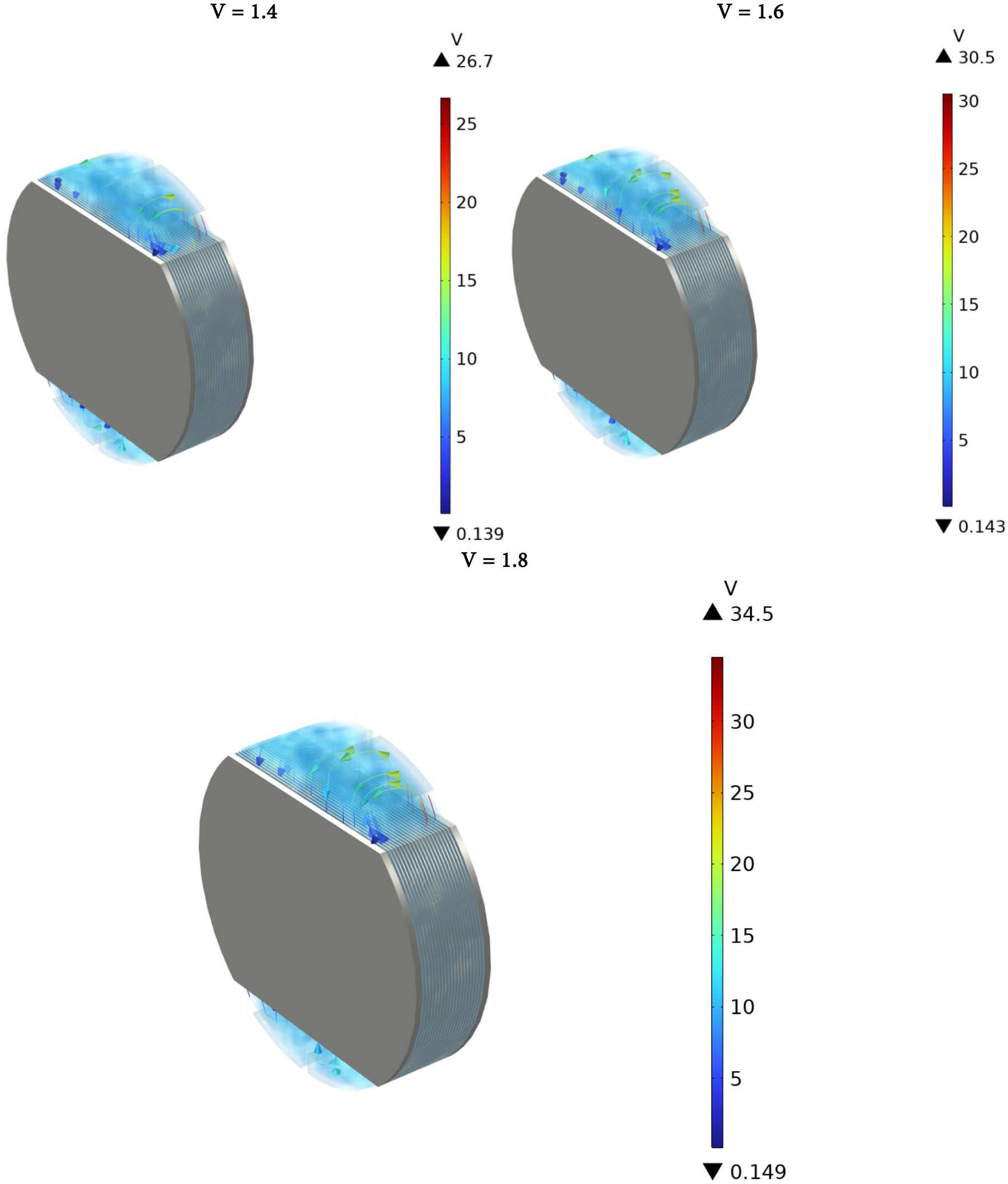
Figure 4: Streamlines for various voltage differences
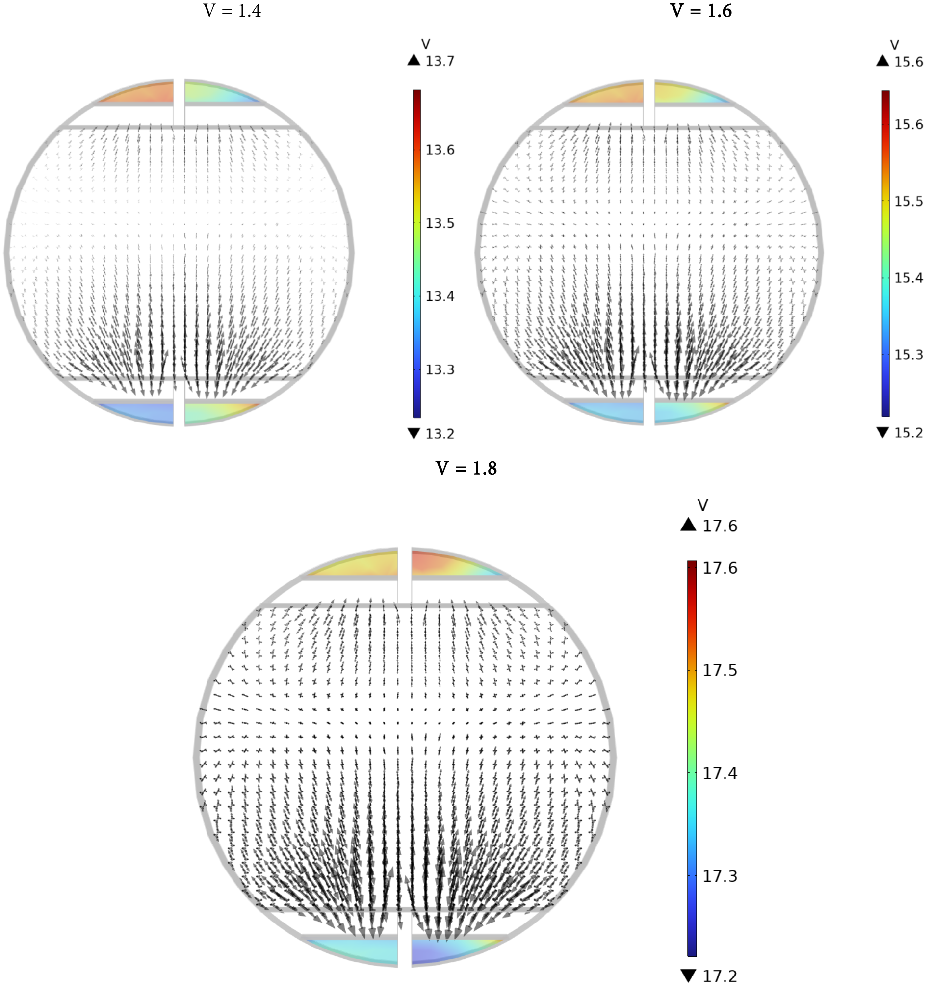
Figure 5: Electrolyte potential (Arrows: Electrode current density vector)
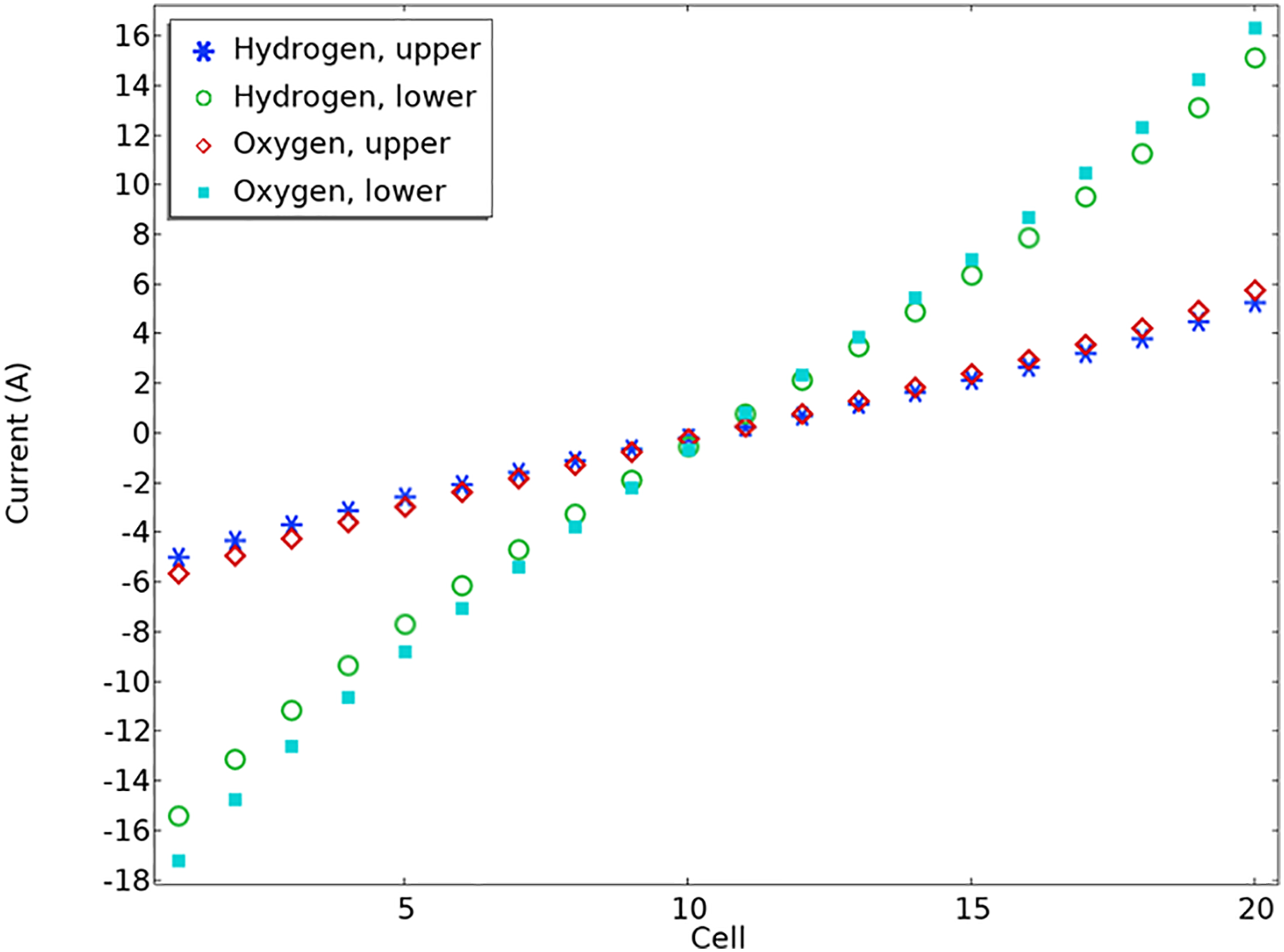
Figure 6: Shunt current per cell for 1.4 V
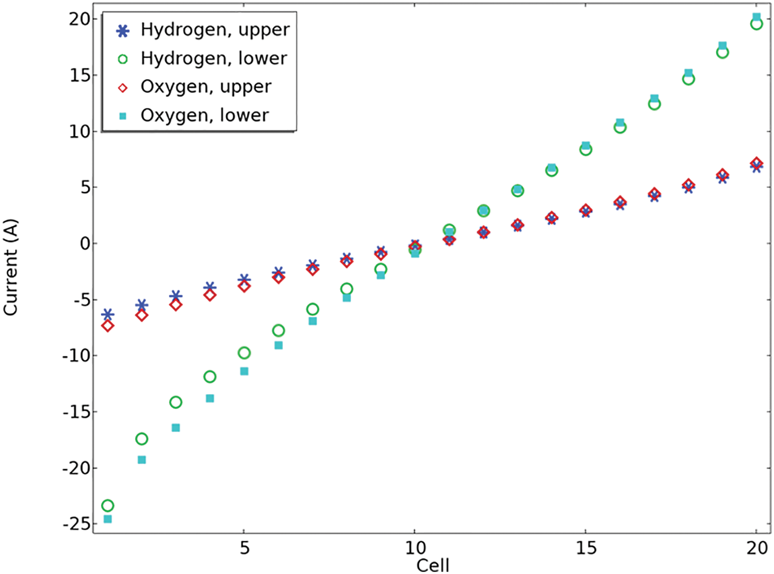
Figure 7: Shunt current per cell for 1.8 V
Shunt currents in the outlet channels are lower than those in the intake channels because of the lower electrolyte volume percentage and consequently lower effective electrolyte conductivity in the upper channels. Furthermore, it is noted that shunt currents become more noticeable as the stack gets closer to the conclusion. In Fig. 7, the elevated stack voltage results in generally higher shunt currents when compared to those in Fig. 6. Furthermore, it can be found that the more the voltage difference, the greater the shunt current. For illustration, it is clear that the maximum value in Fig. 6 is 16 A; however, it has a value of 20 in Fig. 7. In both figures, it is obvious that the current for hydrogen at the upper and lower positions increases gradually with cell number. Oxygen at the lower position has the most negative current, especially at lower cell numbers. The oxygen current at the upper position remains relatively low but positive as the cell number increases. This visualization likely illustrates how different gases and positions influence current flow within the cells over multiple units.
Fig. 8 presents a polarization plot for the stack, where the total current on the x-axis was obtained by integrating the current density across one of the end plates of the stack. This plot also features the open circuit and thermoneutral cell voltage for the given operating conditions. The thermoneutral cell voltage is particularly noteworthy, as extra heat would be necessary to warm the stack if the electrolyzer operates below this voltage. A polarization plot is a graph commonly used in electrochemistry to analyze the performance of electrochemical cells, such as batteries, fuel cells, or corrosion studies. Often, the plot illustrates how the cell voltage decreases as the current increases, highlighting kinetic limitations, overpotentials, and other effects. This figure helps determine parameters like electrode resistance, exchange current density, and overpotentials. Polarization resistance is the slope of the voltage vs. current at low currents. According to this figure, the efficiency can be evaluated, and it can be advantageous to understand limiting factors like charge transfer resistance or mass transport limitations.
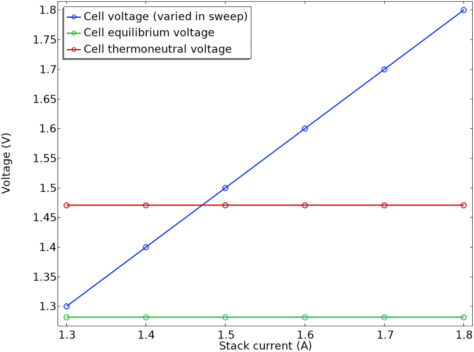
Figure 8: The plot for polarization
We can additionally calculate the coulombic efficiency related to hydrogen production within the stack. The overall current density for hydrogen evolution across all cells is divided by the stack current multiplied by the number of cells to determine this efficiency statistic.
Coulombic efficiency (also called charge efficiency) measures how effectively an electrochemical process converts injected or extracted charge (in coulombs) into useful products or reactions. It indicates the fraction of charge that contributes to the desired electrochemical reaction. High coulombic efficiency means minimal losses due to side reactions (like corrosion or parasitic reactions). It reflects the effectiveness and stability of an electrochemical system. In Fig. 9, the Coulombic efficiency is shown. The interaction among various polarization effects leads to the efficiency being reduced at lower stack currents.
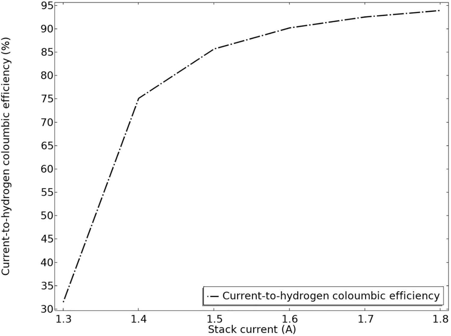
Figure 9: Current to hydrogen Coulombic productivity
In Fig. 9, it can be found that the efficiency increases as the stack current rises, starting around 32% at 1.3 A and approaching close to 93%–94% at 1.75 A. The curve shows a trend of improving efficiency with higher current, indicating more effective hydrogen production or utilization at higher current levels.
The findings from this study have practical implications for real-world alkaline water electrolysis (AWE) systems:
• Electrolyte Management and Design Optimization
The observation that lower electrolyte volume fraction in the upper channels reduces effective conductivity suggests that careful management of electrolyte distribution is critical. In commercial AWE systems, uniform electrolyte distribution is essential to ensure consistent current distribution and minimize parasitic shunt currents, which can lead to efficiency losses. Designing flow channels and electrolyte filling strategies to maintain optimal electrolyte volume throughout the stack can enhance overall performance.
• Stack Efficiency and Scalability
The significant increase in efficiency at higher current densities (from ~32% to ~94%) indicates that operating AWE systems at higher currents can substantially improve energy utilization. This supports the development of larger, more efficient stacks for industrial hydrogen production, where maximizing current density is key to economic viability.
• Shunt Currents and Long-Term Performance
The finding that shunt currents become more prominent near the end of the stack highlights the importance of stack design to mitigate these losses. In real systems, this can be addressed through improved bipolar plate design, electrical insulation, or current balancing techniques, ensuring long-term stability and efficiency.
• Thermal and Electrolyte Considerations
Operating uniformly at 85°C and understanding the role of ohmic losses help in designing thermal management systems. Maintaining optimal temperature and electrolyte composition can sustain high efficiency in large-scale applications.
• Economic and Environmental Impact
Insights into efficiency gains at higher currents contribute to reducing the cost per kilogram of hydrogen produced, making electrolysis more economically competitive. Improving efficiency directly reduces energy consumption and greenhouse gas emissions associated with hydrogen production.
In summary, these findings emphasize the importance of electrolyte management, current optimization, and stack design in scaling up alkaline electrolysis technology for commercial and industrial use, ultimately aiding the transition to cleaner hydrogen energy systems.
Since the turn of the 20th century, alkaline electrolysis has been a proven method for producing hydrogen on a megawatt scale. In order to produce clean hydrogen, an examination of parasitic shunt currents in alkaline water electrolysis has been conducted. A stack of 20 cells has been studied. The model includes a 6 M potassium hydroxide electrolyte, bipolar plates, and steel end plates. Butler-Volmer kinetics equations are used to represent the electrode surfaces. Mass transport restrictions in the gas phase are disregarded, while ohmic losses in the electrode and electrolyte phases are taken into consideration. The equations are solved using an auxiliary sweep, changing the average cell voltage from 1.3 to 1.8 V, and the model runs isothermally at 85°C. The findings demonstrate that lower electrolyte volume fraction in the upper channels results in reduced effective electrolyte conductivity, which in turn causes lower shunt currents in the outlet channels as opposed to the inlet channels. Furthermore, it is noted that shunt currents become more noticeable as the stack gets closer to the conclusion. Efficiency is calculated by dividing the electrical energy required to generate the energy in the stack by the greatest energy output (per unit of time) that a fuel cell operating under the same conditions might provide. Current to hydrogen Coulombic productivity shows that the efficiency increases as the stack current rises, starting around 32% at 1.3 A and approaching close to 93%–94% at 1.75 A. The curve shows a trend of improving efficiency with higher current, indicating more effective hydrogen production or utilization at higher current levels.
Acknowledgement: We thank all the staff of the Faculty of Mechanical Engineering at the University of Tabriz for their cooperation and kind support throughout my research period.
Funding Statement: The authors received no specific funding for this study.
Author Contributions: The authors acknowledge their contributions to the manuscript as follows: study conception and design: Tuhid Pashaee Golmarz; data gathering: Seyyed Kazem Yekani; analysis and interpretation of findings: Tuhid Pashaee Golmarz, Seyyed Kazem Yekani; draft manuscript preparation: Tuhid Pashaee Golmarz, Seyyed Kazem Yekani, Ebrahim Abdi Aghdam. All authors reviewed the results and approved the final version of the manuscript.
Availability of Data and Materials: The data that underlie the findings of this research can be obtained from the Corresponding Author, Seyyed Kazem Yekani, upon a reasonable request.
Ethics Approval: Not applicable.
Conflicts of Interest: The authors declare no conflicts of interest to report regarding the present study.
Nomenclature
| AWE | Alkaline water electrolysis |
| p | Pressure |
| u | Velocity vector |
| Greek Letter | |
| Bulk conductivity | |
| Electrolyte volume fraction | |
| Density | |
| Viscosity | |
References
1. Decourt B. Electricity storage factbook. Gravenhage, The Netherlands: Schlumberger-SBC Energy Institute; 2013. [Google Scholar]
2. Mahlia TMI, Saktisahdan TJ, Jannifar A, Hasan MH, Matseelar HSC. A review of available methods and development on energy storage; technology update. Renew Sustain Energy Rev. 2014;33:532–45. doi:10.1016/j.rser.2014.01.068. [Google Scholar] [CrossRef]
3. Abdalla AM, Hossain S, Nisfindy OB, Azad AT, Dawood M, Azad AK. Hydrogen production, storage, transportation and key challenges with applications: a review. Energy Convers Manag. 2018;165(3):602–27. doi:10.1016/j.enconman.2018.03.088. [Google Scholar] [CrossRef]
4. Zhang F, Zhao P, Niu M, Maddy J. The survey of key technologies in hydrogen energy storage. Int J Hydrogen Energy. 2016;41(33):14535–52. doi:10.1016/j.ijhydene.2016.05.293. [Google Scholar] [CrossRef]
5. Dutta S. A review on production, storage of hydrogen and its utilization as an energy resource. J Ind Eng Chem. 2014;20(4):1148–56. doi:10.1016/j.jiec.2013.07.037. [Google Scholar] [CrossRef]
6. Mazloomi K, Gomes C. Hydrogen as an energy carrier: prospects and challenges. Renew Sustain Energy Rev. 2012;16(5):3024–33. doi:10.1016/j.rser.2012.02.028. [Google Scholar] [CrossRef]
7. FreedomCAR, Fuel Partnership. Hydrogen production: overview of technology options [Internet]. [cited 2025 Jul 1]. Available from: https://www1.eere.energy.gov/hydrogenandfuelcells/pdfs/h2_tech_roadmap.pdf. [Google Scholar]
8. Schiebahn S, Grube T, Robinius M, Tietze V, Kumar B, Stolten D. Power to gas: technological overview, systems analysis and economic assessment for a case study in Germany. Int J Hydrogen Energy. 2015;40(12):4285–94. doi:10.1016/j.ijhydene.2015.01.123. [Google Scholar] [CrossRef]
9. Gahleitner G. Hydrogen from renewable electricity: an international review of power-to-gas pilot plants for stationary applications. Int J Hydrogen Energy. 2013;38(5):2039–61. doi:10.1016/j.ijhydene.2012.12.010. [Google Scholar] [CrossRef]
10. Ball M, Weeda M. The hydrogen economy—vision or reality? In: Compendium of hydrogen energy. Amsterdam, The Netherlands: Elsevier; 2016. p. 237–66. doi:10.1016/b978-1-78242-364-5.00011-7. [Google Scholar] [CrossRef]
11. Albrecht U, Altmann M, Michalski J, Raksha T, Weindorf W. Analyse der Kosten erneuerbarer gase. Ottobrunn, Germany: Ponte Press; 2013. (In German). [Google Scholar]
12. Nationale Organisation Wasserstoff. Integration von wind-wasserstoff-systemen in das energiesystem. In: Proceedings of the 17th Treffen des BMK BioMethan-Kuratoriums des BRM und der FEE; 2014 Oct 1; Falkenhagen, Germany. (In German). [Google Scholar]
13. Hy Under. Assessment of the potential, the actors and relevant business cases for large scale and long term storage of renewable electricity by hydrogen underground storage in Europe—executive summary [Internet]. [cited 2025 Jul 1]. Available from: https://cordis.europa.eu/project/id/303417/reporting. [Google Scholar]
14. Arlt ML, Cardoso GF, Weng D. Hydrogen storage applications in industrial microgrids. In: 2017 IEEE Green Energy and Smart Systems Conference (IGESSC); 2017 Nov 6–7; Long Beach, CA, USA. doi:10.1109/IGESC.2017.8283465. [Google Scholar] [CrossRef]
15. Ganeshan A, Holmes DG, Meegahapola L, McGrath BP. Enhanced control of a hydrogen energy storage system in a microgrid. In: 2017 Australasian Universities Power Engineering Conference (AUPEC); 2017 Nov 19–22; Melbourne, VIC, Australia. doi:10.1109/AUPEC.2017.8282434. [Google Scholar] [CrossRef]
16. Wong M, Afrouzi HN. Hydrogen energy storage system: review on recent progress. Energy Eng. 2025;122(1):1–39. doi:10.32604/ee.2024.056707. [Google Scholar] [CrossRef]
17. Lu Y, He B, Jiang J, Lin R, Zhang X, Yang Z, et al. Capacity optimization configuration of hydrogen production system for offshore surplus wind power. Energ Eng. 2023;120(12):2803–18. doi:10.32604/ee.2023.042328. [Google Scholar] [CrossRef]
18. Zhang S, Xue J, Sun X. Suitability evaluation of hydrogen production and hydrogenation station based on AHP-fuzzy comprehensive evaluation method. Energy Eng. 2022;119(4):1547–67. doi:10.32604/ee.2022.019450. [Google Scholar] [CrossRef]
19. Wang Z, Jia Y, Yang Y, Cai C, Chen Y. Optimal configuration of an off-grid hybrid wind-hydrogen energy system: comparison of two systems. Energ Eng. 2021;118(6):1641–58. doi:10.32604/EE.2021.017464. [Google Scholar] [CrossRef]
20. Yu ZY, Lang CC, Gao MR, Chen Y, Fu QQ, Duan Y, et al. Ni–Mo–O nanorod-derived composite catalysts for efficient alkaline water-to-hydrogen conversion via urea electrolysis. Energy Environ Sci. 2018;11(7):1890–7. doi:10.1039/c8ee00521d. [Google Scholar] [CrossRef]
21. Brauns J, Turek T. Alkaline water electrolysis powered by renewable energy: a review. Processes. 2020;8(2):248. doi:10.3390/pr8020248. [Google Scholar] [CrossRef]
22. Santos DMF, Sequeira CAC, Figueiredo JL. Hydrogen production by alkaline water electrolysis. Quím Nova. 2013;36(8):1176–93. doi:10.1590/s0100-40422013000800017. [Google Scholar] [CrossRef]
23. Wang C, Lu H, Mao Z, Yan C, Shen G, Wang X. Bimetal Schottky heterojunction boosting energy-saving hydrogen production from alkaline water via urea electrocatalysis. Adv Funct Mater. 2020;30(21):2000556. doi:10.1002/adfm.202000556. [Google Scholar] [CrossRef]
24. Cheng H, Fei J, Wen J, Tu ST. Predictive maintenance of alkaline water electrolysis system for hydrogen production based on digital twin. Int Conf Comput Exp Eng Sci. 2023;27(2):1. doi:10.32604/icces.2023.09663. [Google Scholar] [CrossRef]
25. Luo S, Zhang T, Xu H, Zhang J, Zhao H, Yun J, et al. Optimizing alkaline water electrolysis: a dual-model approach for enhanced hydrogen production efficiency. Energies. 2024;17(21):5512. doi:10.3390/en17215512. [Google Scholar] [CrossRef]
26. Henkensmeier D, Cho W, Jannasch P, Stojadinovic J, Li Q, Aili D, et al. Separators and membranes for advanced alkaline water electrolysis. Chem Rev. 2024;124(10):6393–443. doi:10.1021/acs.chemrev.3c00694. [Google Scholar] [PubMed] [CrossRef]
27. d’Amore-Domenech R, Carrillo I, Navarro E, Leo TJ. Alkaline electrolysis for hydrogen production at sea: perspectives on economic performance. Energies. 2023;16(10):4033. doi:10.3390/en16104033. [Google Scholar] [CrossRef]
28. Najafi B, Haghighatshoar F, Ardabili S, Band SS, Chau KW, Mosavi A. Effects of low-level hydroxy as a gaseous additive on performance and emission characteristics of a dual fuel diesel engine fueled by diesel/biodiesel blends. Eng Appl Comput Fluid Mech. 2021;15(1):236–50. doi:10.1080/19942060.2021.1871960. [Google Scholar] [CrossRef]
29. Buttler A, Spliethoff H. Current status of water electrolysis for energy storage, grid balancing and sector coupling via power-to-gas and power-to-liquids: a review. Renew Sustain Energy Rev. 2018;82(3):2440–54. doi:10.1016/j.rser.2017.09.003. [Google Scholar] [CrossRef]
30. Versteeg HK, Malalasekera W. An introduction to computational fluid dynamics: the finite volume method. 2nd ed. Harlow, UK: Pearson Education Ltd.; 2007. [Google Scholar]
31. Das MK, Mukherjee PP, Muralidhar K. Modeling transport phenomena in porous media with applications. Berlin/Heidelberg, Germany: Springer; 2018. doi:10.1007/978-3-319-69866-3. [Google Scholar] [CrossRef]
32. Martínez EL, Jaimes R, Gomez JL, Filho RM. CFD simulation of three-dimensional multiphase flow in a rotating packed bed. In: 22nd European Symposium on Computer Aided Process Engineering. Amsterdam, The Netherlands: Elsevier; 2012. p. 1158–62. doi:10.1016/b978-0-444-59520-1.50090-7. [Google Scholar] [CrossRef]
33. El Ouadefli L, El Akkad A, El Moutea O, Moustabchir H, Elkhalfi A, Luminiţa Scutaru M, et al. Numerical simulation for brinkman system with varied permeability tensor. Mathematics. 2022;10(18):3242. doi:10.3390/math10183242. [Google Scholar] [CrossRef]
Cite This Article
 Copyright © 2025 The Author(s). Published by Tech Science Press.
This work is licensed under a Creative Commons Attribution 4.0 International License , which permits unrestricted use, distribution, and reproduction in any medium, provided the original work is properly cited.
 Downloads
 Citation Tools