
 Submit a Paper
 Propose a Special lssue
 Open Access
ARTICLE
Design of 400 V-10 kV Multi-Voltage Grades of Dual Winding Induction Generator for Grid Maintenance Vehicle
Electric Power Research Institute, State Grid Jiangsu Electric Power Co., Ltd., Nanjing, 211103, China
* Corresponding Author: Tiankui Sun. Email:
(This article belongs to the Special Issue: Advanced Energy Management and Process Optimization in Industrial Manufacturing: Towards Smart, Sustainable, and Efficient Production Systems)
Energy Engineering 2026, 123(1), 16 https://doi.org/10.32604/ee.2025.070213
Received 10 July 2025; Accepted 05 September 2025; Issue published 27 December 2025
 View Full Text
 Download PDF
Abstract
To ensure an uninterrupted power supply, mobile power sources (MPS) are widely deployed in power grids during emergencies. Comprising mobile emergency generators (MEGs) and mobile energy storage systems (MESS), MPS are capable of supplying power to critical loads and serving as backup sources during grid contingencies, offering advantages such as flexibility and high resilience through electricity delivery via transportation networks. This paper proposes a design method for a 400 V–10 kV Dual-Winding Induction Generator (DWIG) intended for MEG applications, employing an improved particle swarm optimization (PSO) algorithm based on a back-propagation neural network (BPNN). A parameterized finite element (FE) model of the DWIG is established to derive constraints on its dimensional parameters, thereby simplifying the optimization space. Through sensitivity analysis between temperature rise and electromagnetic loss of the DWIG, the main factors influencing the machine’s temperature are identified, and electromagnetic loss is determined as the optimization objective. To obtain an accurate fitting function between electromagnetic loss and dimensional parameters, the BPNN is employed to predict the nonlinear relationship between the optimization objective and the parameters. The Latin hypercube sampling (LHS) method is used for random sampling in the FE model analysis for training, testing, and validation, which is then applied to compute the cost function in the PSO. Based on the relationships obtained by the BPNN, the PSO algorithm evaluates the fitness and cost functions to determine the optimal design point. The proposed optimization method is validated by comparing simulation results between the initial design and the optimized design.Keywords
To avoid large-scale power outages caused by routine maintenance or emergencies, which could severely impact industries and daily life, the demand for mobile power sources (MPS) has been steadily increasing [1–6]. Comprising mobile emergency generators (MEGs) and mobile energy storage systems (MESS), MPS provide flexible backup power for critical loads and enhance power system resilience [1–3]. The combination of MESS with MEGs improves generator fuel efficiency and reduces energy losses [1], while the use of MESS also helps lower carbon emissions [2]. Together, MPS offer mobility, rapid deployment, and high adaptability in response to grid contingencies or disaster scenarios [3]. Recent research has focused on strategies to improve MPS planning and operation for resilience enhancement, including stochastic investment planning to minimize total resilience costs [4], coordinated deployment of MEGs and MESS to strengthen system robustness [5], and routing and scheduling frameworks for optimal MPS dispatch during distribution system restoration [6].
Generally, MEGs provide a single voltage level due to the specific rated output voltage of the onboard generator, which limits their versatility across different voltage levels. For example, a generator rated at 400 V cannot directly supply 10 kV for a high-voltage grid. According to the literature, one approach to achieving multi-voltage power supply is to employ multiport transformers [7–9]. For instance, a transformer topology based on a three-phase four-arm full-bridge modular multilevel converter is presented in [7] to provide a 10 kV AC/±10 kV distribution grid. However, such topologies require multiple power converters and transformers, leading to large size, high complexity, low integration, and increased cost, which may render them unsuitable for MEG applications.
To improve the flexibility of MEGs and achieve multi-voltage power supply, another approach is to increase the output ports of the generator to provide different voltage levels [10–12]. The use of a multi-winding generator allows different output voltages to be obtained by adjusting the turn ratios between windings, eliminating the need for external transformers or full-bridge modular multilevel converters, and enabling a more compact and integrated structure. Double-fed induction generators (DFIGs) can provide multiple output ports, making them capable of delivering different voltage levels. However, DFIGs rely on brushes and slip rings, which increase maintenance requirements and reduce overall reliability. To overcome these limitations, dual-winding induction generators (DWIGs) offer a brushless rotor design, which reduces maintenance costs and enhances reliability [12]. In addition, DWIGs can provide different voltages by adjusting the turn ratio between the two stator windings, and both windings are capable of supplying power to the grid [13–15]. The flexibility in designing the turn ratios allows DWIGs to accommodate a wide range of voltage and current requirements [16–18]. A higher turns ratio produces a low-voltage, high-current output, whereas a lower turns ratio yields a high-voltage, low-current output. In this study, the MEG is required to deliver two voltage levels—400 V and 10 kV—and the DWIG with dual stator windings is well-suited for this purpose. Optimizing the design further improves the overall efficiency of the generator.
The dual stator windings of the DWIG result in increased design complexity relative to standard induction machines. Several studies have addressed DWIG optimization [19–23]. For instance, a genetic algorithm has been applied to maximize efficiency in wind farm applications [19]; however, in that study, the two windings have different pole pairs, unlike the DWIG considered here. Particle swarm optimization has been used to determine the optimal current in the control winding (CW) for low-voltage, high-current applications [20]. To reduce the size of the associated power converter, the excitation capacitor has been optimized to minimize CW current [21]. Additionally, system parameters have been tuned to achieve improved static and dynamic performance [22]. Despite these advancements, high-voltage applications—where the power winding must deliver 10 kV—pose significant insulation and winding design challenges. To date, there appears to be no research specifically addressing the design of DWIGs for 10 kV high-voltage applications.
This paper proposes a design method for DWIG employing a BPNN-improved-PSO algorithm. A parametric finite element model of the DWIG is established to derive the design constraints. Due to the difficulty of determining the nonlinear relationship between the DWIG parameters and performance, a BPNN is used to predict the relationship between design parameters and optimization objectives. The PSO algorithm is then employed to identify the optimal design point that minimizes the cost function predicted by the BPNN. Finally, finite element simulation results at the optimal point validate the effectiveness of the proposed design method.
The configuration of the DWIG-based MPS is shown in Fig. 1. The DWIG has a squirrel-cage rotor and two groups of stator windings. One is 400 V low-voltage winding (LW) and the other is 10 kV high-voltage winding (HW). The LW is connected to a static excitation converter, which provides the reactive power. The 400 V LW is connected to the 400 V, 50 Hz grid, while the HW is connected to the 10 kV, 50 Hz grid. The LW has fewer turns than the HW. By flexibly designing the turns ratio between the HW and LW, the DWIG can output multiple voltage levels.
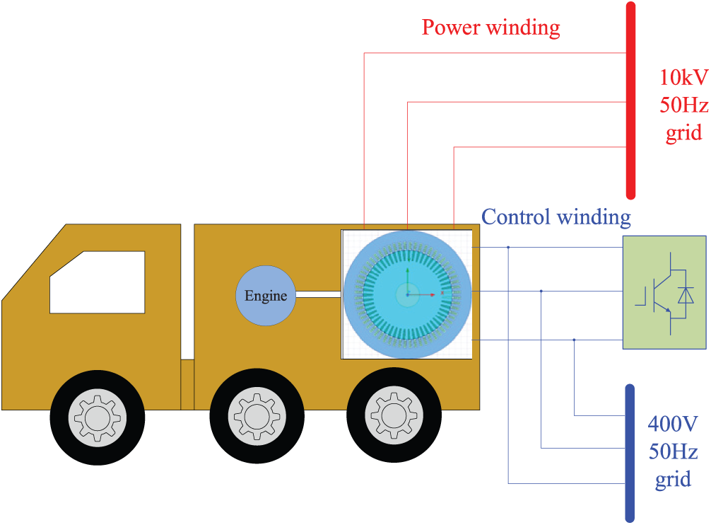
Figure 1: DWIG-based 400 V-10 kV MPS
3 Initial Design of 400 V–10 kV DWIG
When the DWIG is generating, the rotor absorbs mechanical energy, which is transmitted to the stator and converted into electrical energy. The transmitted power is called electromagnetic power, which can be expressed as the calculated power. The sizing equation can be expressed as follows:
where PNl and PNh are the LW and HW rated power, respectively, kwl and kwh are the LW factor and HW factor, respectively, Bδ is the air-gap flux density, Al and Ah are the surface current density of LW and HW, respectively, n is the rotor speed, η is the efficiency, cosφ is the power factor, Ce is the motor constant, D1i is the stator inner diameter, lef is the machine length, which can be expressed as in [23]:
where λ is the dimension ratio, p is the number of pole pairs.
The surface current density Al and Ah are determined as follows:
where m is the phase number, Nl and Nh are the LW and HW turn number of every phase, respectively, Il and Ih are the LW and HW current, respectively.
Substituting (2), (3) into (1), the stator inner diameter can be determined as:
For the DWIG, it needs reactive power for the excitation in generation. The reactive power used for the generating excitation is provided by the static excitation converter on the LW side. Defining the rated active power as PN, the total reactive power of the DWIG QN is:
where φ is the power factor angle. The current of LW can be derived from (6):
where PNl is the active power of LW side and Ul is the phase voltage of the LW.
The HW current Ih can be expressed as:
Substituting (6), (7) into (5), the initial design of stator inner diameter D1i can be determined as:
The stator slot number is related to the coil number. More stator slot number brings higher winding distribution factor but needs more insulation. With this consideration, the number of the stator slots is determined as 48. The number of slots in every pole and every phase q = 4. The rotor slot is selected as 58.
Fig. 2 shows the quarter section-view structure of DWIG. The wide-open-parallelled slot is selected for the convenience of the coiling and insulation.
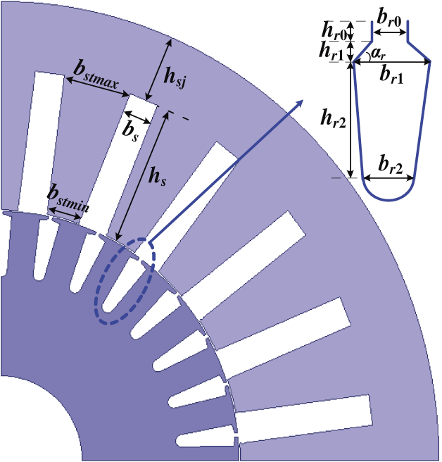
Figure 2: The quarter section-view structure of DWIG
The core loss is related to the saturation. Generally, the flux density of the stator teeth should be no more than the constraint point of the steel (about 1.8 T). The minimum width of the stator tooth bstmin should satisfy the condition as follows:
where KFe is the lamination factor. t1 can be expressed as follow:
According to Fig. 2, bstmin should also satisfy the condition by dimension limit:
where αs is the stator slot angle, bs is the stator slot width, and δ is air gap length. The stator tooth maximum width is:
The stator outside diameter is calculated as follows:
where hs and hsj are the stator slot height and stator yoke height, respectively.
The rotor slot dimensions can be calculated as follows:
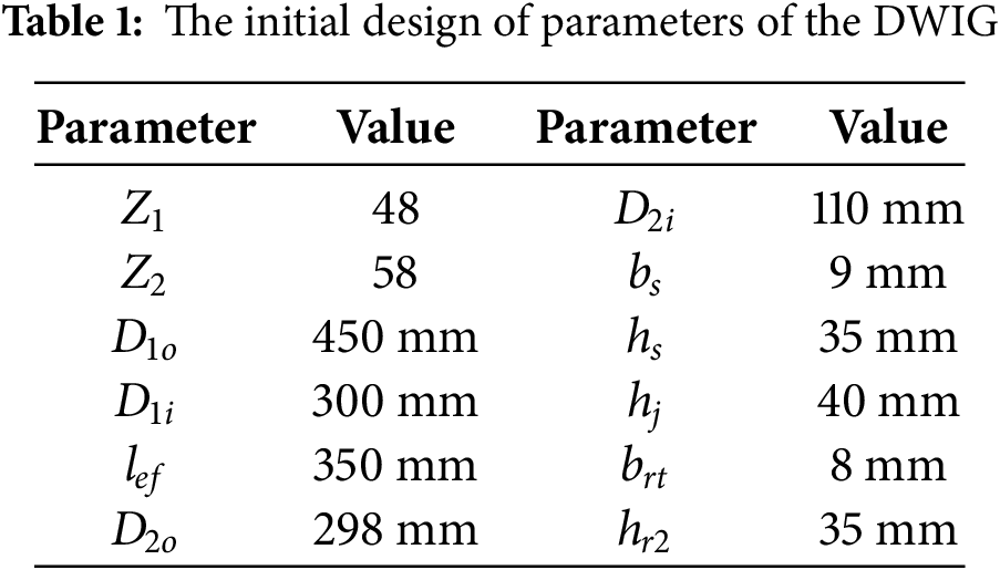
The geometric constraint expressed in (10) to (13) can be used to reduce the design variables and establish the parametric model of the DWIG. The detailed parameters of the initial design of the DWIG are shown in Table 1.
The HW and LW should be designed to output 400 V and 10 kV voltage. This can be achieved by the turn ratio between HW and LW. Assuming that the induced voltage of the LW and HW are El and Eh, respectively, the turn ratio K is:
where kl, kh are the winding factors of LW and HW, respectively. Since the DWIG uses a short-pitched distributed winding, both LW and HW have the same number of slots per pole per phase. With the short pitch of 10/12, the winding factor of the LW and HW kl = kh = 0.922.
For the HW, the line voltage is 10 kV. For the convenience of the insulation, the stator slot is selected as the parallel-type slot and the winding configuration is bar winding. Unlike conventional electric machines, the DWIG has a set of stator windings with a 10 kV rated line voltage. This voltage level poses a challenge to the insulation. Thus, the insulations include the main insulation between the slot and windings, layer insulation, wire insulation, and row insulation, as shown in Fig. 3.
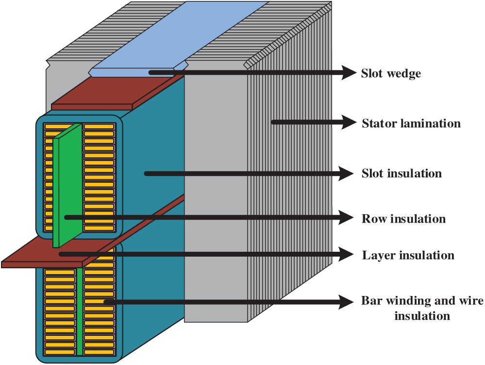
Figure 3: The insulation types of the stator
4 Optimization Design Using BPNN-Improved-PSO
4.1 Sensitivity Analysis of the Optimization Variables
The DWIG employs natural cooling. Since the generator’s rated speed is relatively low, rotor mechanical stress has little impact on temperature rise. To avoid too high temperature rise, the electromagnetic loss of the DWIG should be optimized. To obtain the law of temperature vs. the copper loss and iron loss, a sensitivity analysis of the temperature rise of DWIG is carried out, as shown in Fig. 4.
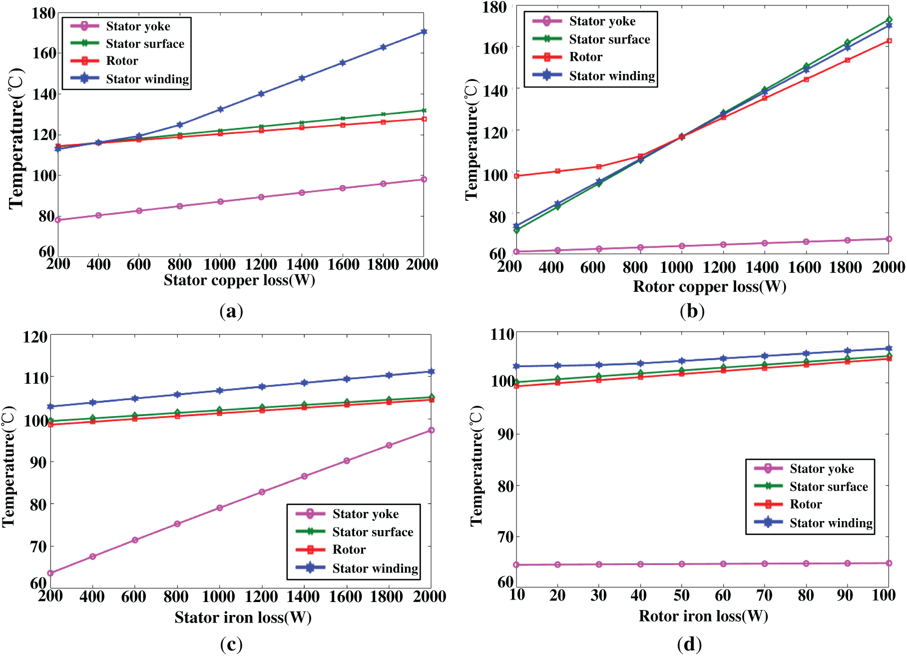
Figure 4: Sensitivity analysis of the temperature rise with different loss. (a) Temperature rise with stator copper loss; (b) Temperature rise with rotor copper loss; (c) Temperature rise with stator iron loss; (d) Temperature rise with rotor iron loss
From the initial design, the rotor iron loss is much smaller than the copper loss. The copper loss and stator iron loss are varied from 200 W to 2000 W, while the rotor iron loss is varied from 10 W to 100 W. As the stator copper loss increases from 200 W to 2000 W, the stator winding temperature rises from approximately 115°C to 175°C. The temperature ranges of the stator yoke, stator surface and rotor are no more than 20°C. Rotor copper loss primarily affects the heating of the stator surface, stator winding, and rotor. Every 200 W increase in rotor copper loss results in an approximate 10°C rise in the stator surface and winding temperature. The stator iron loss mainly influences the stator yoke temperature, and every 100 W increase of stator iron loss will yield about 5°C temperature rise on the stator yoke. The rotor iron loss has little effect on the temperature rise because the rotor iron loss is relatively small. According to the sensitivity analysis, it can be concluded that the copper loss and iron loss have main influence on the temperature rise of the DWIG. Thus, the electromagnetic loss should be optimized.
4.2 Optimization Algorithm Based on BP-Improved PSO
In this paper, a BPNN-improved-PSO method is proposed for DWIG. The chart flow of the method is shown in Fig. 5.
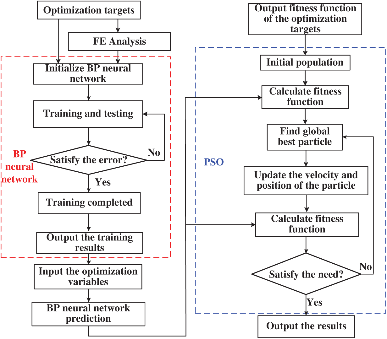
Figure 5: The chart flow of the proposed optimization method
Initially, 100 sample points of the finite element analysis are calculated by the FE model. For the accurate sampling results, the LHS method is used to overcome the problems of the undesired correlations between the input variables, which may have significant influence on the prediction results [24,25]. Fig. 6 shows the sampling points in 3D design space established by LHS method.
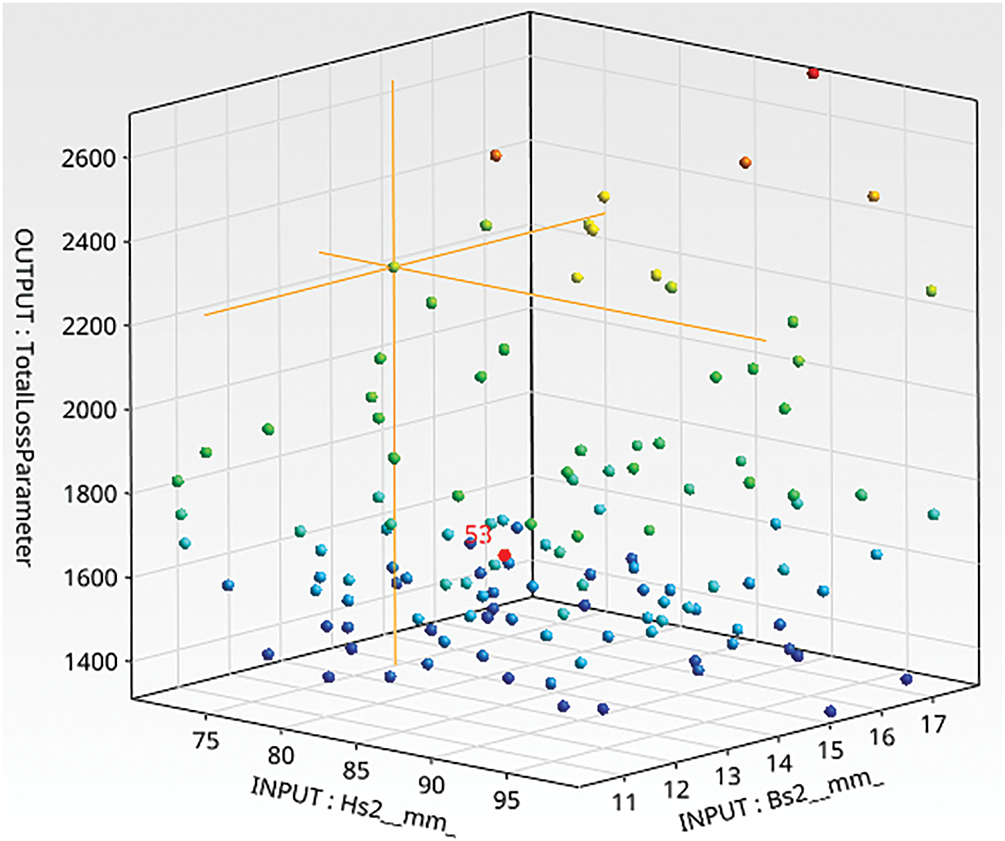
Figure 6: The distribution of the sampling points using LHS in design space
4.3 Fitness Function Prediction Based on BP Neural Network
The relationship between the optimization variables and electromagnetic loss is nonlinear and it is difficult to be determined. BPNN algorithm is suitable to predict the relationship between the inputs and outputs. BPNN is a multilayer neural network algorithm, which can approximate the nonlinear function through the hidden layers and nodes. The structure of the BP neural network algorithm is shown in Fig. 7.
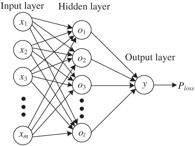
Figure 7: The structure of the BPNN algorithm
The input layer corresponds to the optimization variables, and the output layer corresponds to the electromagnetic loss Ploss. The optimization variables are processed from the input layer through the hidden layer to the output layer, where the BPNN computes the output values and the squared error between the predicted and expected values. If the calculated squared error does not reach the expected value, the weights and thresholds are adjusted to minimize the error between the predicted and expected outputs. In this paper, the input x = [D1i, lef, hs, hsj, bs2, brt, hr2], output y = Ploss, and the hidden layer nodes o = [o1, o2, …, ol]. The outputs of the hidden layer are [26]:
where
where m is the number of inputs and n is the number of outputs. In this paper, the inputs are the optimization variables and the output is the optimization target, while m = 7 and n = 1. According to (17), the number of the hidden layer node l ranges from 4 to 13. The fitting regressions with different hidden layer nodes have been tested, as shown in Table 2.
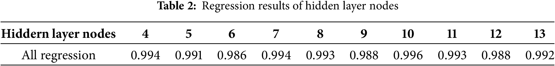
It can be seen from Table 2 that when the hidden layer node is 10, the regression is highest (0.996). Thus, this number of hidden layer node was selected.
The outputs of the output layer are [26]:
where
The mean square error is used to describe the accuracy of the fitness function by BP neural network:
To balance model accuracy with computational burden, a set of 100 sample points was ultimately selected for the BPNN training. 70% of the sample points are used for the training, 15% of the sample points are used to test and another 15% of the sample points are used to validate. If the error is less than the threshold value, the fitness function predicted by the BPNN is used for the fitness calculation in PSO. Fig. 8 shows the performance of the BPNN. The best validation is at 6 epoch, and the MSE is 0.001227. The regression of the training is 0.9982. It can be seen that the fitting regression of the BPNN is good and the test error is less than 0.01.
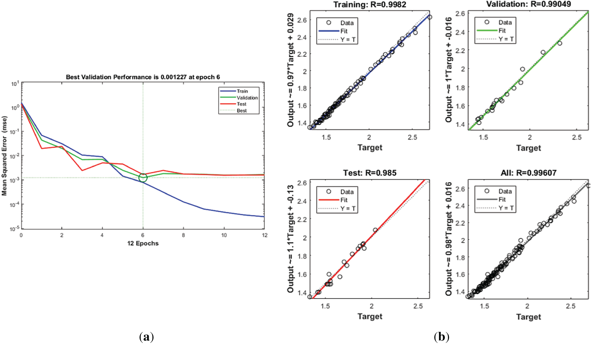
Figure 8: The results of the BPNN. (a) Mean square error of BPNN; (b) Regression of the BPNN
4.4 BPNN-PSO Optimization Method
The fitness function of the optimization target obtained by BPNN is regarded as the cost function in PSO to get the minimum value. Considering that the power factor, current density and flux density are crucial indicators of the DWIG operation, the optimization cost function and the constraint conditions are as follows:
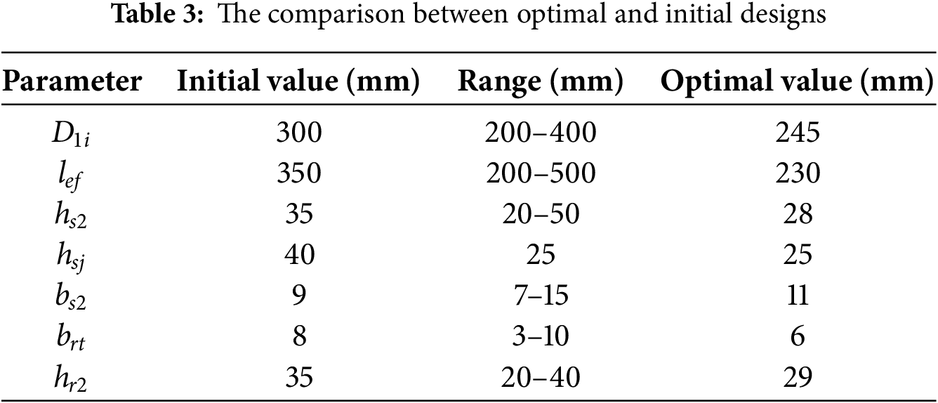
The constraint of the power factor of the DWIG is no less than 0.8. The main reason is that lower power factor yields more reactive power in the generator. For natural cooled electric machine, the current density of the winding is normally not more than 5 A/mm2, which is selected as the constraint of the stator winding current density. The flux density is also constrained to a maximum of 1.8 T, corresponding to the knee point of the machine’s steel material. Fig. 9 shows the optimization results of the PSO. At 226 interactions, the optimal point is reached. The corresponding electromagnetic loss is about 1.93 kW. The optimization variables at optimal point are listed in Table 3.
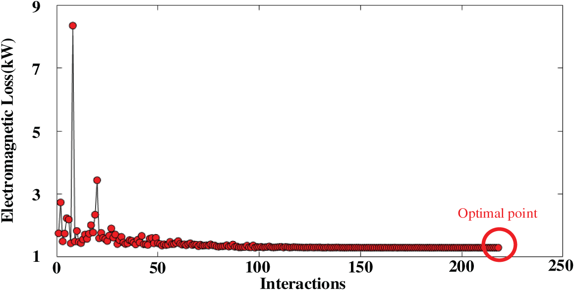
Figure 9: The results of the PSO
To validate the proposed design method for the 400 V–10 kV DWIG, a finite element analytical model of 40 kW–50 Hz DWIG is established in the analysis software ANSYS. Fig. 10 shows the simulation results of the initial design and the optimized one.
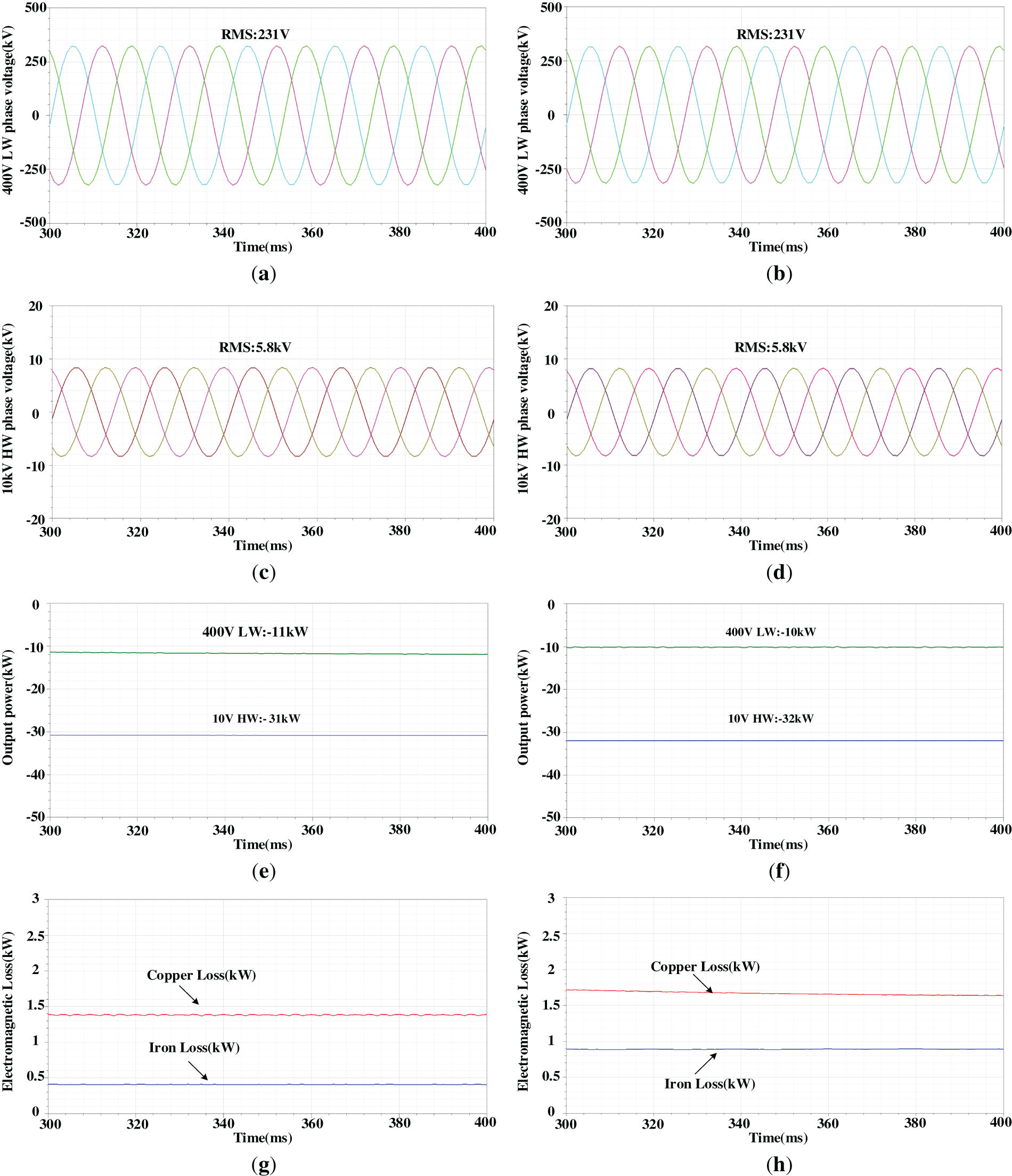
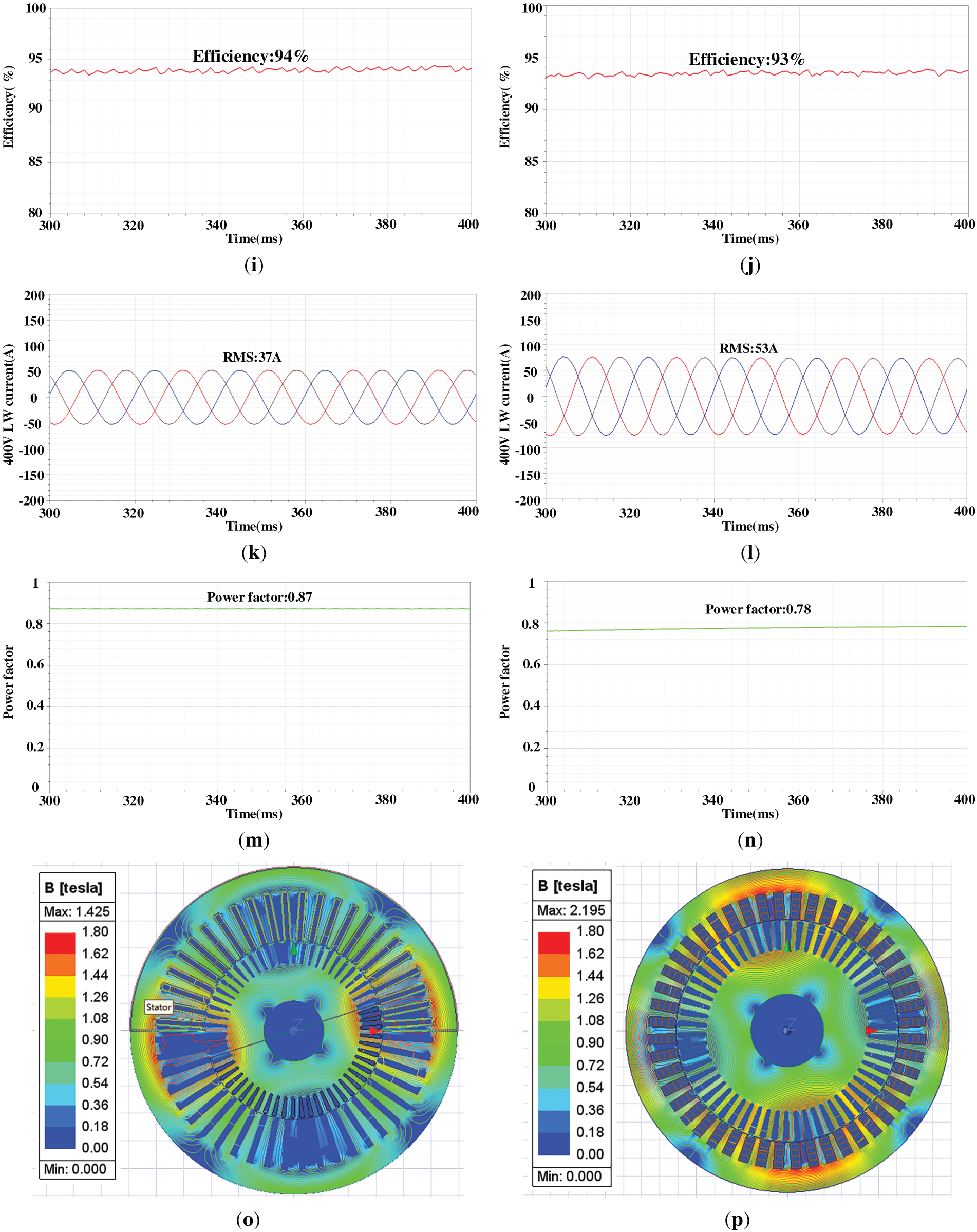
Figure 10: The comparison of simulation results between the initial design and optimal design. (a) The output voltage of 400 LW of initial design; (b) The output voltage of 400 LW of optimal design; (c) The output voltage of 10 kV HW of initial design; (d) The output voltage of 10 kV HW of optimal design; (e) The output power of initial design; (f) The output power of optimal design; (g) The electromagnetic loss of initial design; (h) The electromagnetic loss of optimal design; (i) The efficiency loss of initial design; (j) The efficiency loss of optimal design; (k) The LW phase current of initial design; (l) The LW phase current of optimal design; (m) The power factor of initial design; (n) The power factor of optimal design; (o) The flux density distribution of initial design; (p) The flux density distribution of optimal design
From Fig. 10a,d, in both the optimized and initial designs, the LW phase voltage is about 231 V and the HW phase voltage is about 5.8 kV, corresponding to 400 V and 10 kV line voltages, respectively. From Fig. 10e,f, both the optimized and initial designs deliver 42 kW of active power. With the same output active power, from Fig. 10g,h, the copper loss of the optimized one is about 1.41 kW while the initial design is about 1.63 kW. The iron loss of the optimized design is around 0.44 kW, whereas that of the initial design is approximately 0.92 kW. The electromagnetic loss of the optimized one is about 1.85 kW while the initial design is about 2.55 kW. Moreover, the LW phase current is about 37 A in the optimized design, compared with 53 A in the initial design, indicating that the reactive power of the LW in the initial design is much higher than in the optimized design. As shown in Fig. 10m,n, the power factor is about 0.78 for the initial design and approximately 0.87 for the optimized design. This also causes the larger copper loss of the LW since the phase current is larger than the optimal one. Correspondingly, the optimized design achieves an efficiency of approximately 94%, an improvement of 1% over the initial design.
Fig. 10o,p show the flux density of the machine. In the initial design, the flux density is relatively low. The stator teeth flux density is 0.71 T; the stator yoke flux density is 0.91 T; the rotor teeth flux density is 0.93 T; and the rotor yoke flux density is 0.6 T. Thus, the steel core is not fully utilized. In optimal design, the stator teeth flux density is 1.44 T; the stator yoke flux density is 1.54 T; the rotor teeth flux density is 1.4 T; and the rotor yoke flux density is 0.8 T. This indicates that the core steel material is more effectively utilized. With the same rated output power, the initial design has a larger volume than the optimized one, including a larger stator inner diameter and core length. Besides, the initial design also has larger yoke height and rotor teeth width, which causes lower flux density than the optimized design. For clarity, the comparison of the initial design and the optimal design is listed in Table 4.
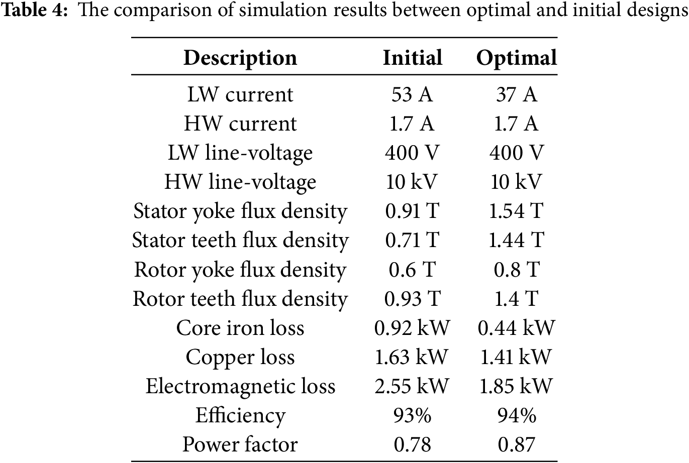
Compared with the initial design, the dimensions of the optimal design are significantly reduced, and the electromagnetic loss is reduced by about 27.4%, while the efficiency is increased by 1%. In addition, due to more efficient utilization of the core material, the power factor also improves.
This paper presents a design method for a 400 V–10 kV DWIG used in MEG by employing a PSO algorithm improved with a BP neural network.
(1) A parametric FE model of the DWIG is established, incorporating constraints on dimension parameters. The stator and rotor slot dimensions are governed by mathematical relationships, which can help reduce the number of optimization variables.
(2) Sensitivity analysis between the DWIG temperature rise and electromagnetic loss identifies the latter as the main factor influencing machine temperature. A BP neural network is then employed to accurately model the relationship between electromagnetic loss and the optimization variables, achieving high regression-prediction accuracy.
(3) To ensure effective sampling, the LHS method is used to generate sample points from the FE model for training, testing, and validation. The predicted relationships between the optimization targets and variables are then used to compute the fitness and cost functions in the PSO algorithm.
(4) Based on the relationship obtained by BP neural network, the PSO algorithm evaluates the fitness and cost functions to determine the optimal design point. By the comparison of the simulation results between the initial design and the optimal point, the optimization method is validated.
Acknowledgement: This research was supported by State Grid Jiangsu Electric Power Co., Ltd. The author expresses sincere gratitude to all those who participated in this study.
Funding Statement: This research was funded by the Science and Technology Projects of State Grid Corporation of China (Project No. J2024136).
Author Contributions: The authors confirm contribution to the paper as follows: Conceptualization: Tiankui Sun, Shuyi Zhuang; Methodology: Tiankui Sun; Software: Tiankui Sun; Validation: Tiankui Sun, Shuyi Zhuang, Yongling Lu; Formal analysis: Tiankui Sun; Investigation: Tiankui Sun, Wenqiang Xie; Resources: Tiankui Sun; Data curation: Tiankui Sun; Writing—original draft preparation: Tiankui Sun; Writing—review and editing: Tiankui Sun, Shuyi Zhuang, Yongling Lu; Visualization: Tiankui Sun, Ning Guo; Supervision: Sudi Xu; Project administration: Sudi Xu; Funding acquisition: Tiankui Sun. All authors reviewed the results and approved the final version of the manuscript.
Availability of Data and Materials: The authors confirm that the data supporting the findings of this study are available within the article.
Ethics Approval: Not applicable.
Conflicts of Interest: The authors declare no conflicts of interest to report regarding the present study.
References
1. Rangel N, Li H, Aristidou P. An optimisation tool for minimising fuel consumption, costs and emissions from Diesel-PV-Battery hybrid microgrids. Appl Energy. 2023;335:120748. doi:10.1016/j.apenergy.2023.120748. [Google Scholar] [CrossRef]
2. Liu X, Zhao F, Hao H, Liu Z. Opportunities, challenges and strategies for developing electric vehicle energy storage systems under the carbon neutrality goal. World Electr Veh J. 2023;14(7):170. doi:10.3390/wevj14070170. [Google Scholar] [CrossRef]
3. Lei S, Chen C, Li Y, Hou Y. Resilient disaster recovery logistics of distribution systems: co-optimize service restoration with repair crew and mobile power source dispatch. IEEE Trans Smart Grid. 2019;10(6):6187–202. doi:10.1109/TSG.2019.2899353. [Google Scholar] [CrossRef]
4. Shi W, Liang H, Bittner M. Stochastic planning for power distribution system resilience enhancement against earthquakes considering mobile energy resources. IEEE Trans Sustain Energy. 2024;15(1):414–28. doi:10.1109/TSTE.2023.3296063. [Google Scholar] [CrossRef]
5. Yang Z, Dehghanian P, Nazemi M. Seismic-resilient electric power distribution systems: harnessing the mobility of power sources. IEEE Trans Ind Appl. 2020;56(3):2304–13. doi:10.1109/TIA.2020.2972854. [Google Scholar] [CrossRef]
6. Lei S, Chen C, Zhou H, Hou Y. Routing and scheduling of mobile power sources for distribution system resilience enhancement. IEEE Trans Smart Grid. 2019;10(5):5650–62. doi:10.1109/TSG.2018.2889347. [Google Scholar] [CrossRef]
7. Lu S, Deng J, Li S, Shao Y, Li K. A multiport power electronic transformer based on three-phase four-arm full-bridge modular multilevel converter. IEEE Trans Power Electron. 2024;39(12):16174–86. doi:10.1109/TPEL.2024.3438440. [Google Scholar] [CrossRef]
8. Xu X, Tai N, Hu Y, Liu T, Fan C, Geng Q. Study on optimal operation of multi-port cascaded power electronic transformer cluster. In: 2019 IEEE Sustainable Power and Energy Conference (iSPEC). 2019 Nov 21–23; Beijing, China: IEEE; 2019. p. 2318–23. doi:10.1109/iSPEC48194.2019.8975033. [Google Scholar] [CrossRef]
9. Zhao B, Song Q, Li J, Wang Y, Liu W. Modular multilevel high-frequency-link DC transformer based on dual active phase-shift principle for medium-voltage DC power distribution application. IEEE Trans Power Electron. 2017;32(3):1779–91. doi:10.1109/tpel.2016.2558660. [Google Scholar] [CrossRef]
10. Ma Y, Zhu D, Hu J, Liu R, Zou X, Kang Y. Optimized design of demagnetization control for DFIG-based wind turbines to enhance transient stability during weak grid faults. IEEE Trans Power Electron. 2025;40(1):76–81. doi:10.1109/TPEL.2024.3457528. [Google Scholar] [CrossRef]
11. Alavi-Eshkaftaki A, Rabiee A, Kargar A, Boroujeni ST. An applicable method to improve transient and dynamic performance of power system equipped with DFIG-based wind turbines. IEEE Trans Power Syst. 2020;35(3):2351–61. doi:10.1109/TPWRS.2019.2954497. [Google Scholar] [CrossRef]
12. Basak S, Chakraborty C, Pal BC. A new configuration of dual Stator induction generator employing series and shunt capacitors. IEEE Trans Energy Convers. 2018;33(2):762–72. doi:10.1109/TEC.2017.2763459. [Google Scholar] [CrossRef]
13. Basak S, Chakraborty C. A new optimal current control technique for dual Stator winding induction generator. IEEE J Emerg Sel Top Power Electron. 2017;5(2):820–32. doi:10.1109/JESTPE.2016.2646919. [Google Scholar] [CrossRef]
14. Barrado-Rodrigo JA, Talpone JI, Martinez-Salamero L. Variable-speed wind energy conversion system based on a dual Stator-winding induction generator. IET Renew Power Gener. 2017;11(1):73–80. doi:10.1049/iet-rpg.2016.0186. [Google Scholar] [CrossRef]
15. Liu H, Bu F, Huang W, Qin H, Tan Y, Qian Z. Linear active disturbance rejection control for dual-Stator winding induction generator AC power system. IEEE Trans Ind Electron. 2023;70(7):6597–607. doi:10.1109/TIE.2022.3204960. [Google Scholar] [CrossRef]
16. Kavousi A, Fathi SH, Milimonfared J, Soltani MN. Application of boost converter to increase the speed range of dual-Stator winding induction generator in wind power systems. IEEE Trans Power Electron. 2018;33(11):9599–610. doi:10.1109/TPEL.2018.2797095. [Google Scholar] [CrossRef]
17. Hassan Zamani M, Hossein Riahy G, Abedi M. Rotor-speed stability improvement of dual Stator-winding induction generator-based wind farms by control-windings voltage oriented control. IEEE Trans Power Electron. 2016;31(8):5538–46. doi:10.1109/TPEL.2015.2495256. [Google Scholar] [CrossRef]
18. Liu H, Yan Y, Bu F, Huang W, Jiang W, Tan Y, et al. Sensorless control with adaptive speed observer using power winding information for dual-Stator winding induction starter/generator. IEEE Trans Ind Electron. 2024;71(2):1388–98. doi:10.1109/TIE.2023.3253965. [Google Scholar] [CrossRef]
19. Keshtkar H, Zarchi HA. Multi-objective optimal design of dual Stator winding induction generators based on genetic algorithm and finite element analysis. In: 2019 International Power System Conference (PSC). 2019 Dec 9–11; Tehran, Iran: IEEE; 2019. p. 142–9. doi:10.1109/PSC49016.2019.9081487. [Google Scholar] [CrossRef]
20. Liu L, Zhao G. Optimal design of dual stator-winding induction generator system based on particle swarm algorithm. In: 2010 Third International Conference on Information and Computing. 2010 Jun 4–6; Wuxi, China: IEEE; 2010. p. 175–8. doi:10.1109/ICIC.2010.228. [Google Scholar] [CrossRef]
21. Li Y, Hu Y, Huang W, Liu L, Zhang Y. The capacity optimization for the static excitation controller of the dual-stator-winding induction generator operating in a wide speed range. IEEE Trans Ind Electron. 2009;56(2):530–41. doi:10.1109/TIE.2008.2003363. [Google Scholar] [CrossRef]
22. Benzaoui K, Bouguerra A, Zeghlache S, Boukhari M, Zeghlache A. Field oriented control technique of a wind system based on a dual Stator induction generator. In: 2022 International Conference of Advanced Technology in Electronic and Electrical Engineering (ICATEEE). 2022 Nov 26–27; M’sila, Algeria: IEEE; 2022. p. 1–6. doi:10.1109/ICATEEE57445.2022.10093703. [Google Scholar] [CrossRef]
23. Lipo TA. Principles of design. In: Introduction to AC machine design. Hoboken, NJ, USA: John Wiley & Sons, Inc.; 2017. [Google Scholar]
24. Shin PS, Woo SH, Zhang Y, Koh CS. An application of Latin hypercube sampling strategy for cogging torque reduction of large-scale permanent magnet motor. IEEE Trans Magn. 2008;44(11):4421–4. doi:10.1109/TMAG.2008.2002479. [Google Scholar] [CrossRef]
25. Kim JB, Hwang KY, Kwon BI. Optimization of two-phase in-wheel IPMSM for wide speed range by using the Kriging model based on Latin hypercube sampling. IEEE Trans Magn. 2011;47(5):1078–81. doi:10.1109/TMAG.2010.2096409. [Google Scholar] [CrossRef]
26. Tian Y, Fu D, Li G. Research on the generalization problem of BP neural network. IEEE Access. 2024;12(1):125416–26. doi:10.1109/access.2024.3452710. [Google Scholar] [CrossRef]
Cite This Article
 Copyright © 2026 The Author(s). Published by Tech Science Press.
This work is licensed under a Creative Commons Attribution 4.0 International License , which permits unrestricted use, distribution, and reproduction in any medium, provided the original work is properly cited.
 Downloads
 Citation Tools