
 Submit a Paper
 Propose a Special lssue
 Open Access
ARTICLE
Adaptive Grid-Interface Control for Power Coordination in Multi-Microgrid Energy Networks
Department of Electrical Engineering, Prince Faisal Centre for Renewable Energy Studies and Application, Northern Border University, Arar, 73213, Saudi Arabia
* Corresponding Author: Sk. A. Shezan. Email:
(This article belongs to the Special Issue: Integration of Renewable Energies with the Grid: An Integrated Study of Solar, Wind, Storage, Electric Vehicles, PV and Wind Materials and AI-Driven Technologies)
Energy Engineering 2026, 123(1), 4 https://doi.org/10.32604/ee.2025.073418
Received 17 September 2025; Accepted 17 November 2025; Issue published 27 December 2025
 View Full Text
 Download PDF
Abstract
Modern power systems increasingly depend on interconnected microgrids to enhance reliability and renewable energy utilization. However, the high penetration of intermittent renewable sources often causes frequency deviations, voltage fluctuations, and poor reactive power coordination, posing serious challenges to grid stability. Conventional Interconnection Flow Controllers (IFCs) primarily regulate active power flow and fail to effectively handle dynamic frequency variations or reactive power sharing in multi-microgrid networks. To overcome these limitations, this study proposes an enhanced Interconnection Flow Controller (e-IFC) that integrates frequency response balancing and an Interconnection Reactive Power Flow Controller (IRFC) within a unified adaptive control structure. The proposed e-IFC is implemented and analyzed in DIgSILENT PowerFactory to evaluate its performance under various grid disturbances, including frequency drops, load changes, and reactive power fluctuations. Simulation results reveal that the e-IFC achieves 27.4% higher active power sharing accuracy, 19.6% lower reactive power deviation, and 18.2% improved frequency stability compared to the conventional IFC. The adaptive controller ensures seamless transitions between grid-connected and islanded modes and maintains stable operation even under communication delays and data noise. Overall, the proposed e-IFC significantly enhances active-reactive power coordination and dynamic stability in renewable-integrated multi-microgrid systems. Future research will focus on coupling the e-IFC with tertiary-level optimization frameworks and conducting hardware-in-the-loop validation to enable its application in large-scale smart microgrid environments.Keywords
Microgrids, which may function in isolation mode or grid-connected mode, are becoming essential parts of present day power systems. According to IEEE, a micro grid is “Within well defined electrical limits, a micro grid is an assembly of dispersed energy sources and associated loads that operate as a single, controlled entity with regard to the grid.” [1]. In an ideal world, interconnected micro grids would provide as a steady supply or load for the primary grid. The short-term availability of renewable energy sources is a major obstacle to establishing efficient micro grid performance. Primarytaining a steady power flow to or from the primary grid is harder as the use of renewable energy sources grows. The difficulty of controlling power flow across various grid connections makes this problem even more difficult in micro grids with several connections.
The optimal operational condition can only be achieved if the Dispatchable and Distributed Generating Units (DDGUs) inside the microgrid can entirely offset variations in regional demand and generation [2]. The variations in local generation or demand may result from load fluctuation, the intermittency of renewable energy sources, Non-Dispatchable Distributed Generating Units (NDDGUs), or from the partial or total failure of any another generation resource. Developing maximum efficiency is significantly more difficult for microgrids with higher renewable integration and variable loads/demand than for those with less renewable integration and more consistent load profiles.
Frequency variations and reactive power imbalances represent significant challenges to the performance and dependability of these systems. The development and implementation of diverse clean energy resources have presented new issues concerning nearly all facets of microgrid operations and stability [3]. Primary maintenance of consistent power flow and system dependability requires efficient control techniques, especially for maintenance of reactive and active power and maintenance of frequency.
Investigators have been investigating solutions to alleviate these issues for an extended period. Numerous strategies for the control and management of active and reactive (P&Q) electricity inside a microgrid are documented in the paper [4]. Latest projects in this domain mostly concentrate on neither the interior voltage regulation of microgrids or the economic dispatch of distributed generation units. Everything that the recently cited papers considered a microgrid with a single link to the national grid.
The research in [5] proposed a two-stage optimisation structure particularly designed for the CCHP-based ICES by day-ahead in the distribution electricity market (DEM). Inside this framework, a recent derivative model is presented among the ICES operators (ICESOs) and the Distribution System Operator (DSO). The scheme facilitates enhanced active and reactive power scheduling, leading to optimal scheduling of distributed resources. This leads to improved operating efficiency, improved scheduling, which is more reliable, and better utilization of local energy resources in the community energy system.
An enhanced predictive control for renewable-based microgrids is introduced in [6]. The adopted approach is based on a Finite Control Set-Model Predictive Control (FCS-MPC) algorithm for grid-connected and islanding operation. The control system combines voltage support, power sharing regulation, and negative sequence current suppression schemes which guarantee system robustness and operation security. The method can decrease the computational complexity and the number of switching operations of the inverter, and can improve the voltage characteristics, the power quality, and the harmonic distortion suppression. In addition, reference [6] presents a supporting MPC framework for real-time DERs optimisation and coordination to reconfigure the dynamic and resilient microgrid operation.
Another duals contribution is presented in [7], where a predictive model for Optimal Management of Energy (OME) in renewable-based hybrid microgrids (HMGs) is proposed. To address this issue, a modified MPC based on Firefly algorithm (MMPC-IFA) is proposed. A reference for the active and the reactive power is formed by the method and has the particular advantage of simplifying the switching sequences for voltage source converters. Its primary aim is to control the active and reactive powers by minimizing a cost function. Simulation results show that a MPC based on the IFA, when utilized for HMGs driven by renewables, can minimize operational expenditures (OPEX), guarantee a certain level of energy, and reduce voltage distortion.
The parallel operation of converters for voltage sources and synchronous power sources in a microgrid is discussed in [8], which proposes for a droop-based frequency management approach. The study presented a monitoring central microcontroller to primarytain constant system frequencies.
A thorough comparison and evaluation of reactive power sharing techniques in microgrids functioning in islanded mode is presented in [9,10]. The report provided a review of the proposed communication-free reactive power sharing methods outlined in the related literature. The comparative research determined that the novel approaches represent enhancements over the conventional Q/V sagging method and exhibit significant sensitivity to network setup and other characteristics.
A refined VSG control method utilising fuzzy logic is given in [11]. This combined management technique for distributing electricity is advised for islanded microgrids.
The management of DERs in microgrids has raised enough interest as a response to the demand of efficient and reliable energy systems. With the increased penetration of renewables and energy storage devices, control and coordination of DERs are playing a vital role in improving the microgrid stability and performance. Most of the works in this area of the literature address different control strategies to achieve an optimal USE within microgrids, with particular attention to the PCC, and decentralized systems to work together in a proper way. A primary solution for the coordination of DERs within microgrids is the two-level control strategy, used in recent researches. The combination of set-point manipulation and local control actions enables the enhancement of microgrid operation regimes, specifically in low-inertia systems. The methodology only considers the PCC, and it is able to perform well under different scenarios when power is generated or consumed, being stable even for the sudden variation of power injection or absorption. Case studies well as high-fidelity experimental tests have also demonstrated the effectiveness of these strategies in practical application. However, though the two-level control method performs well in local coordination, it does not solve the problem of dynamic power allocation in inter-connected multi-microgrid network, and there still exist a gap between the local optimal and the optimal in the whole grid [12].
Concurrently, one other important line of research is addressing the problem of decentralized coordination of AC/DC power interfaces in hybrid microgrids. The approaches utilize adaptive inverse control theorists to regulate the accurate active power sharing of both BCs, achieving constant ac/dc bus voltages. This flexibility enables the system to effectively react to abrupt power flow changes, which is indispensable for the operational stability of microgrids with renewable power generation. Nonetheless, this approach is primaryly concentrating on the AC/DC power interface and has not been made applicable to the more comprehensive problem of controlling power flows among multiple interconnected MG, where a response in real-time and the optimal participation operation of the DER units is a must.
Another important aspect of microgrid control is the design of more efficient droop control algorithm for frequency regulation of microsources in microgrid. Such algorithms help the system primarytain a balance between power generation and consumption by adjusting droop coefficients to control frequency’s stability. This method is especially applicable to weakly connected low-voltage microgrids in which the power mismatch is more serious. Although the adaptive droop control approach is superior in stability, it is mostly constrained for single microgrid and cannot realize the coordination of distributed generations in multi-microgrid systems, which is crucial for large-scale microgrid systems.
Hierarchical control architecture in grid-connected microgrids is presented for better participation in the frequency regulation market. They use distributed energy resources and flexible loads to follow regulation signals from the Regional Transmission Organization (RTO) and enhance power sharing in the microgrid. These arrangements enable microgrids to support overall grid stability while maximizing their own internal efficiency. However, one of their limitations is that these frameworks are target on single microgrids efficiency and dynamic coordination of DERs in the multiple microgrids or the coupling systems are not taken into account.
A among DG units of IGMs using centralized control mechanism has been discussed in the literature [13]. The scheme has been developed in such a way as to be robust against potential communication failures, which constitute a major source of incorrect reactive power allocations and thereby voltage instability. Under normal operation, the adaptive digital resistivity control is used in distributed manner, whereby reduced voltage oscillations and increased operating reliabilities are performed through centralized, although in case of communication breakdown at least combined central-distributed operation is primarytained for stabilizing and reliability ofvoltage support.
A contrasting perspective is presented in [14] aiming to enhance the power flow control among interconnected MGs in DNs. The paper presents a deep reinforcement learning framework called Multi-Actor-Attention-Critic (MAAC) to address the dimensionality increase of large scale optimisation problems. Balancing active and reactive power in complex and uncertain systems enhances system stability, reduces power losses and computational burden syndrome, the method includes better performance. Further, in order to improve its performance under changing conditions, for example after grid topology, or in case of the change of device operation, transfer learning is used.
One such work is presented in [15], which deals with power coordination problems in mixed AC-DC microgrids. Traditional droop-based control enables power exchange from both directions, but it is easy to generate errors in power distribution and large voltage distortion for the flexible loads. In this paper, the authors propose an adaptive droop program that self-learns and tunes its own settings in response to system states. This type of adaptive control results in a more accurate power transfer and voltage regulation, especially in applications having a single connection point.
The authors in [16] propose a data-driven approach for secure and coordinated VVC in active distribution networks (ADNs) with multiple microgrids. The proposed approach employs CNNs to reproduce the behaviours of microgrid central controllers (MGCCs) and adopts a voltage sensitivity-based compensatory mechanism to enhance reactive power regulation efficiency. In order to prevent FDIAs, the scheme integrates cryptographic technology including GGH, RSA, etc., into the corresponding exchange communication between distribution operators and microgrids. This has to be taken into account for primarytaining not only the operational efficiency but also the data integrity of a distributed communication-based system.
In [17], the authors propose a holistic control and power management strategy (CAPMS) for a hybrid PV-battery microgrid, that can operate in grid-connected and islanded mode. By closely controlling AC and DC bus voltages in real time, the technology guarantees smooth changes between operating modes. By combining MPPT and battery management, it ensures the power balance between supply and demand, even with a solar radiation that varies and under a variable load. Contrastively, reference [18] proposes a fuzzy logics based decentralised reactivity control scheme for PV-based islanded microgrids. This technique is able to allocate loads for PV, battery and the hybrid PV battery in an efficient way based on the state-of-charge and the instantaneous generation capabilities, which exhibits a good flexibility and efficiency and does not need sophisticated central controller.
In [19], it provides a method for voltage regulation of a medium low voltage integrated distribution network by solving coordinated reactive and active power optimisation. Through the formulation of voltage deviation and network losses as the optimisation objective, the authors present an aggregated control strategy that utilises the active power dispatch from energy storage systems (ESS) in combination with reactive power compensation devices. This collaboration of reactive and active power at both low and medium voltage promises an efficient way to reduce the voltage violations of distribution grids.
A more comprehensive view is presented in [20] that makes an in depth comparison between reactive and active power control approaches and [21] which includes a spectrum of control architectures from droop-based schemes, to model predictive control (MPC) and multi agent system (MAS). These studies emphasize the growing presence of renewable energy in microgrids and resulting control issues. They also classify microgrid management into three hierarchical levels: primary, secondary, and tertiary control, dealing with system functions from local stability to primary grid interaction. It is interesting to note, but the discussed works in [20,21] don’t aim directly the strategies for the connection flow, but the cited works are focused mostly on the microgrid which have only one link system.
When IFC was first created and introduced in [22], it was solely intended to control active power flow across several grid connections, which restricted its functionality. IFC lacked visibility and control over the flow of reactive electricity. Second, it used a simple frequency response based on droop. In order to overcome these obstacles, this article suggests improving the fundamental IFC architecture by adding two more control strategies: reactive power flow control (IRFC) and frequency response control and active power flow. By modifying active power flow to primarytain stability, these improvements enable the micro grid to react to frequency variations more successfully. Furthermore, the IRFC promotes voltage stability by guaranteeing that the reactive power flow stays within predetermined bounds. The study investigates how these improvements strengthen the micro grid’s capacity to function in fluctuating grid settings, providing a more reliable approach for both electrical voltage and frequency control, using in-depth simulations.
Despite notable progress in IFC-based coordination strategies, conventional IFCs remain limited in handling reactive power sharing, dynamic frequency deviations, and multi-microgrid coordination under renewable variability. These limitations lead to unstable voltage profiles and poor dynamic performance, especially during grid disturbances or load fluctuations. To address these challenges, this study proposes an enhanced IFC (e-IFC) that integrates frequency response balancing and reactive power flow regulation within a unified control framework. This approach ensures improved active-reactive power coordination, faster dynamic recovery, and greater adaptability to the fluctuating conditions of renewable-integrated microgrids.
To provide a clearer conceptual foundation, the reviewed studies have been grouped thematically into four major categories: predictive control-based schemes, droop and frequency-based coordination, reactive power flow and voltage regulation techniques, and IFC development frameworks. While predictive and droop-based controllers improve dynamic response and load sharing, they often struggle with reactive power imbalances under high renewable penetration. Similarly, prior IFC developments have mainly focused on active power coordination, offering limited integration between frequency and reactive power control. These limitations motivate the present study, which introduces an enhanced IFC (e-IFC) capable of simultaneous active-reactive power regulation and improved stability in interconnected microgrids. In practical microgrid environments, particularly those dominated by renewable energy sources, fluctuations in solar and wind generation often lead to frequency instability, voltage deviations, and inefficient power sharing with the main grid. Enhancing the Interconnection Flow Controller (IFC) provides an effective engineering solution to mitigate these challenges, ensuring resilient operation, stable frequency response, and optimal power exchange in renewable-rich and interconnected microgrid systems.
The enhanced Interconnection Flow Controller (e-IFC) is conceived as a unified and adaptive control structure designed to simultaneously coordinate active and reactive power exchanges between interconnected microgrids and the main grid. Unlike the conventional IFC, which only regulates active power through frequency-based droop characteristics, the proposed e-IFC integrates a dual-loop configuration comprising a frequency response balancing controller for active power regulation and an Interconnection Reactive Power Flow Controller (IRFC) for reactive power management. This design philosophy enables the system to respond adaptively to both frequency and voltage deviations while ensuring decoupled and stable control performance. A conceptual schematic (Fig. 1) has been added to illustrate the integration of these control loops and their interaction within the multi-microgrid environment.
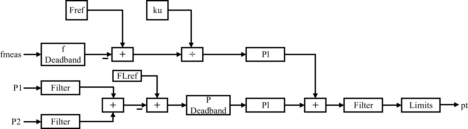
Figure 1: Enhanced controller for balancing active power flow and frequency dynamics
The paper in this study makes a few changes to the underlying design of the IFC controller, that are outlined below:
• to develop an enhanced Interconnection Flow Controller (e-IFC) incorporating frequency response balancing and reactive power flow regulation;
• to evaluate its performance under varying grid frequency deviations and reactive power demands;
• to validate the system’s stability and coordination improvements through dynamic simulations in DIgSILENT PowerFactory.
The rest of the paper is organized as, Section 2 has the methodological approach, Section 3 presents the simulation results for balancing e-IFC controller, Section 4 talks about IRFC controller, Section 5 presents the Simulation Results for IRFC controller and finally Section 6 concludes the paper.
The methodological approach taken in this research project will be illustrated using appropriate conceptual illustrations and mathematical formulations in the part that follows, which is divided into appropriate subsections.
Two improvements have been implemented to the controller’s fundamental layout:
• Active electrical flow and responses to frequencies controller primarytaining
• Interconnection Reactive Power Flow controller (IRFC)
Optimization of Frequency Response and Active Power Flow in Smart Grids
Regardless of whether the primary grid’s frequency deviates from regular, the controller can continue to primarytain a steady active power movement from or forward towards the micro grid because of this design change. Eq. (2) is a modification of the IFC starting Eq. (1), which is shown below.
hither, the active power delivered by the system is presented as the turbine output Pt. The proportional gain in the frequency control loop is Kpf, and the integral gain for frequency control is Kif. Where Kif, KpFL are the proportional and integral gain of the power flow control, respectively.
The enhanced control block diagram of the proposed IFC is shown in Fig. 1. In particular in a grid-connected microgrid, a frequency response method is carried out to ensure global stability by controlling the active power output of DDGUs when the frequency of the grid is not in its notional range.
Increase in Grid Frequency:
If the average frequency of the principal system is increased above the passable frequency deadband, it is indicative of surplus generation available in the system. In such cases the frequency response controller decreases the active power contribution of the DDGUs. This planned shortfall will lead to greater dependence on imports by the microgrid from primary grid. This transfer of line current is contemporaneously observed and detected by the active power flow controller.
Flow Adjustment during Frequency Rise:
Constant DDGU generation, but when the connection is importing active power, consideration is given to the ‘tolerance’ set by the flow deadband and the flow controller moved to switch to control if the limit on import is exceeded. This decreases the import level and returns the amount of connection flow back to its predetermined limit.
Decrease in Grid Frequency:
The network suffers the active power deficit as long as the system frequency is lower than the frequency deadband. The frequency controller commands the DDGUs to put more production online and in that way compensating the need of power and stabilizing the system frequency. This reduces the reliance of the microgrid on imports.
Flow Adjustment during Frequency Drop:
If the decrease of the power imported from the primary grid exceeds acceptable flow deadband, the flow controller controls DDGU generation mildly. This is intended in order to bring the connection power exchange back to the reference range which sets the balanced local vs. grid import/export relationship.
Deadband in Frequency:
This frequency dead band is the range of frequencies that will be tolerated without remedial action. This minimizes undesirable and frequent variations in DDGU output and results in a softer DDGU operation and less mechanical and electrical stress to equipment.
Deadband Flow:
The deadband flow defines the acceptable range of intertie power exchange. Flow controller action on DDGU generation is only activated when deviation exceeds this small band, thus preventing unwanted switching but guaranteeing safe and secure operation.
The gain value
The proportional gain of flow regulation
Balancing Mechanism:
The general balance in the system is accomplished by the combined effort of the frequency response controller and the flow controller. The operation of the frequency loop is assisted by eliminating deviations in intra- and connection-grid frequency, and the flow loop performs the function of the power transfer across connections within allowable margins. We show that these mechanisms beget effective and adaptive control of active power, which allows the microgrid to act as an efficient partner to the primary grid. Selecting proper deadbands and tuning proportional gains (
Communication latency and measurement noise can influence coordinated control actions within interconnected microgrids. To mitigate these issues, the e-IFC integrates adaptive filtering and delay-compensation algorithms within its control architecture. In the event of significant communication delay or data loss, the Distributed Generation Units (DGUs) switch to a local fallback mode, maintaining stable voltage and frequency through autonomous PI-based control loops. This hybrid centralized-decentralized framework ensures reliable performance and system stability under noisy or delayed communication scenarios.
To ensure robustness under communication loss, the e-IFC architecture incorporates a decentralized fallback mechanism. Each Distributed Generation Unit (DGU) maintains an autonomous local control loop based on droop and PI regulation principles, enabling independent frequency and voltage stabilization. During communication interruptions, these local controllers continue to balance active and reactive power within their respective microgrids, preventing instability or overloading. When communication links are restored, the system automatically re-establishes synchronization with the global coordination layer, ensuring smooth reintegration without transient oscillations.
3 Results and Discussions of the Simulation: e-IFC Controller
To evaluate the aforementioned primarytaining e-IFC controller, the following types of simulations were performed utilising the system architecture depicted in Fig. 2:
1. Case Study 1. The primary grid’s regular frequency of 60 Hz is lowered to 59.8 Hz. The IFC and e-IFC controllers are compared using a similar variation in frequency.
2. Case Study 2. The primary grid’s frequency is raised to 60.2 Hz (from notional 60 Hz) in Case Study 2. The IFC and e-IFC controllers are compared using similar variation in frequency.
3. Case Study 3. A stepwise grid isolation test is performed in case study 3. A comparison is made between the efficiency of simple IFC and e-IFC.
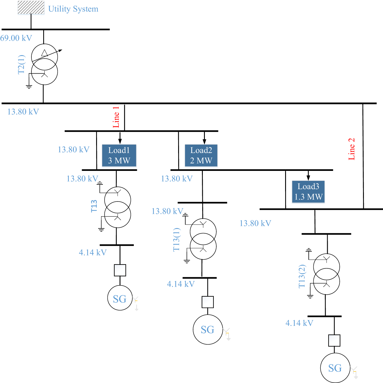
Figure 2: Balanced control of active power flow and frequency response
3.1 Case Study 1: Disturbance Caused by Grid Frequency Drop
In this case, a primary frequency disturbance is emulated to test the response behaviour of the e-IFC controller. Here’s what happened:
1. At
2. At
Through reproducing such disturbances, the tool sheds light on the way the controller handles transient deviations and guaranteeing stability during and after transient frequency disturbances.
Two types of evolution are evident in the simulation:
Event 1: Base Frequency (at
Simulation Scenario: At the fifth sec of the test, the notional frequency of the grid,
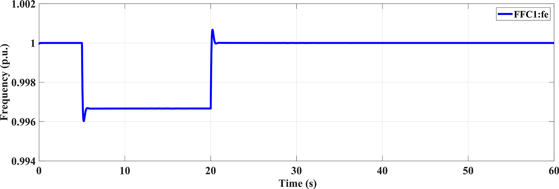
Figure 3: Frequency variation
Microgrid Reaction:
Frequency Regulation Engagement: The reduction in frequency, in turn, triggers the frequency regulation action of the microgrid via e-IFC controller. The disturbance causes the frequency to drop out of the assigned deadband, the controller responds by raising the active power support from the DGSs, as can be seen in Fig. 4.
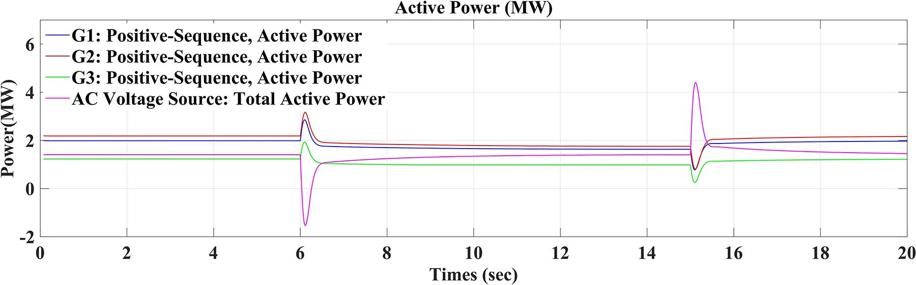
Figure 4: Distribution of Active Power between DDGUs and the primary Grid
Active Power Management: When the output power of DGUs is raised, the microgrid has lower demand on the primary grid. As a result, the power transmitted by the tie-lines from the grid to the microgrid is decreased.
Power Flow Deadband Tracking: Upon the drop of the imported power below the deadband limits the e-IFC controller enables the output of the flow regulation section. It then tries to decrease the DGUs’ generation at this level to avoid over-correction and to keep the delivered power in the reference band the best it can, as it is shown in (Fig. 5).
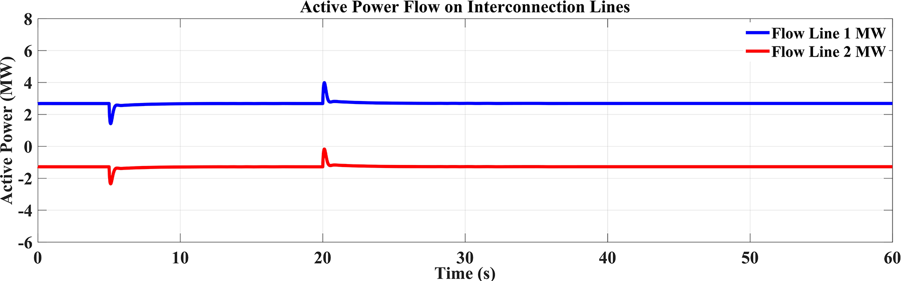
Figure 5: Active power flow dynamics across connection lines
Event 2: Reduction of frequency by progressive grid (at t = 20 s)
Configuring the Simulation:
After 20 s of the analyzing, the frequency of the primary grid is recycled to the notional value of
Microgrid Response
Disengagement of Frequency Response Control:
After restoring the frequency of the grid to its rated value of
Regulation of Active Power Flow:
When the output power of the DGUs is not sufficient, the MG becomes the load for the primary grid and there is a necessity for high energy from the primary grid to supply all the required. This raises the active power flowing through the connection lines between the microgrid and the grid, and thus balances the power flow in order to accommodate the new grid scenarios.
Monitoring of Flow Deadband:
When grid power transfer exceeds a predefined flow deadband, the e-IFC closes the flow control loop by scheduling the flow regulation system to make small changes in demand on the DGUs. This minimizes the reliance on the primary grid by the microgrid, and helps retain power flow inside defined boundaries to avoid an excessive burden of load on the connection.
Test Objectives
Assessment of Frequency Response:
The primary purpose of such a test is to investigate the performance of the eIFC controller using the frequency response function when the primary grid is subject to variations. The system should respond rapidly to these changes to primarytain both the microgrid’s internal balance and the grid frequency to continue network operations.
Active Power Flow Control Assessment:
Beside frequency stabilization, the problem is formulated to ensure that power flow exchange active power between the MG and the primary grid is regulated. It is important to primarytain the flows within a certain range (deadbands) so as not to overload the connection lines and facilitate efficient power exchange during the disturbance and following restoration.
Verification of Controller Coordination:
This test is also intended to assess how the two key functionalities: frequency response control and active power flow regulation are combined and harmonised. The controllers should also collaborate to control the output of the DGUs due to changes in grid conditions. These actions are necessary to keep the grid stable and avoid overcorrection.
Power Flow Stability:
One important point in evaluating the performance of the system’s controller is to observe the flow of power through the connection lines. This flow should reprimary within its predefined deadband, showing that local generation and power import have been effectively balanced, and there have been no disturbances or overload on the grid. This study illustrates the Capacity of the e-IFC controller for fast response to grid disturbances by differing active power consumption at grid frequency variations and thereby primarytaining stability. The proposed approach with frequency regulation and power flow control strategies is able to primarytain well power flow stability and work stably for dynamic operations of the power grid.
Comparison with Basic IFC Controller:
The executed of the simple IFC controller is studied under the same operating conditions. It is to be noted from the responses given in Figs. 6 and 7 that the simple IFC controller has the tendency to let the flow of active power increase among the connections of the lines. Although the frequency controller compensates for the grid frequency event well, the basic IFC controllers flow control scheme does not keep the total active power flow during the grid frequency fall, losing the optimal performance during the disturbance.
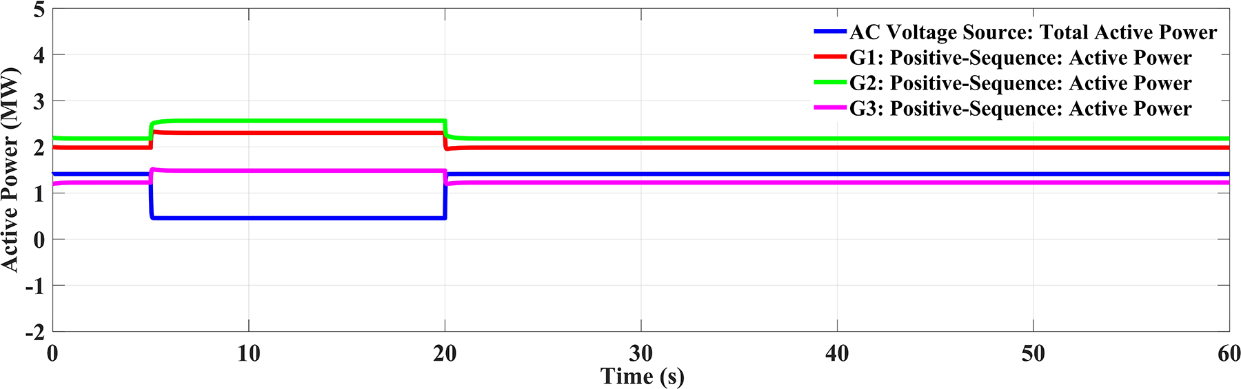
Figure 6: DDGUs and active power from the primary grid using a basic IFC controller
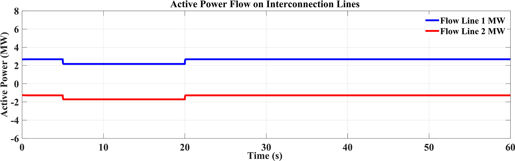
Figure 7: Active power flow via a basic IFC controller across the interconnected lines
Basic IFC Controller’s Performance Evaluation
Obviously, the simple control action only using the IFC controller cannot efficiently regulate the active power exchanged via the connection lines between microgrid and primary grid during the frequency disturbance. This is due to the controller being unable to respond to variations in power demand in real-time, especially under extreme grid conditions such as rapid variations in frequency.
Consequently, the passing active power of the middle network did not fall in the expected range, and the microgrid power exchange management system was unable to stay optimally stable and coordinate with the primary grid.
Frequency Regulation Performance
However, the normal IFC controller’s frequency control showed a rather good response during the disturbance. During a fall in the frequency of grid, the controller of frequency was responsible for controlling the power generated from the DGU considering the dropped frequency to restore it to the notional grid frequency. This capability is to primarytain stability of the microgrid during grid frequency disturbance, especially when the frequency is less than 60 Hz.
3.2 Case 2 Study: Frequency Rise of the Primary Grid
This present study reflects the following scenarios:
1. At
2. The grid frequency recovers to the rated value of
Compared to the first use case where the frequency of the grid was dropped, the e-IFC controller appropriately adjusted the active power schedule at the connection lines to the instructed flow reference when the frequency of the grid grew compared to 60 Hz.
Frequency Rise vs. Frequency Decline
A higher grid frequency means an overrun of energy and the microgrid should lessen the generation of active power to provide equilibrium to the system. Fig. 8 presents the simulator result of the grid frequency increase during the fault. The standard IFC controller in contrast was not designed to more dynamically follow changes in frequencies and active power flows. It effectively regulated the flow of active power through the connection lines to reprimary close to the target reference level, even as the grid frequency increased. This showed better performance than simpler control strategies.
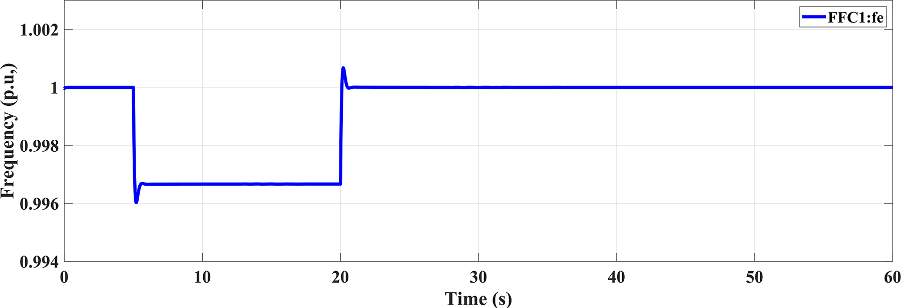
Figure 8: The primary grid’s frequency
Functionality of the e-IFC Controller
Response in Frequency
The e-IFC controller is combining the frequency controller and the flow controller all together in the field. When the primary grid frequency is relatively high, the output of the DGUs is further limited by the frequency response controller. The results in Fig. 9 indicate that the active power generation from the DDGUs resumes to the pre-disturbance level following a very small transient time in response to the grid frequency deviation. Furthermore, the positive active power delivered from the MG to the load stays between the acceptable value limits, which are equal to 1.4 MW (considered as a reference value).
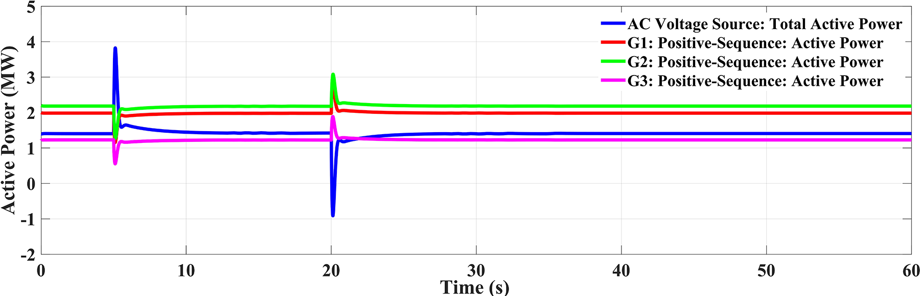
Figure 9: DDGUs and active power from the primary grid via e-IFC
Flow Control Coordination
Meanwhile, the flow controller controls the effective power transmitted via the connection lines. When the DDGU generation is low, the microgrid consumes more power from the primary grid to fulfill its requirement. The e-IFC controller maintains the total power exchange through the connection lines fairly to the assigned reference. The flow chart represented in Fig. 10 shows that the active power flow is allowed through the connection lines, ensuring good control tfairlyo keep the requested power transfer that is aligned with the reference.
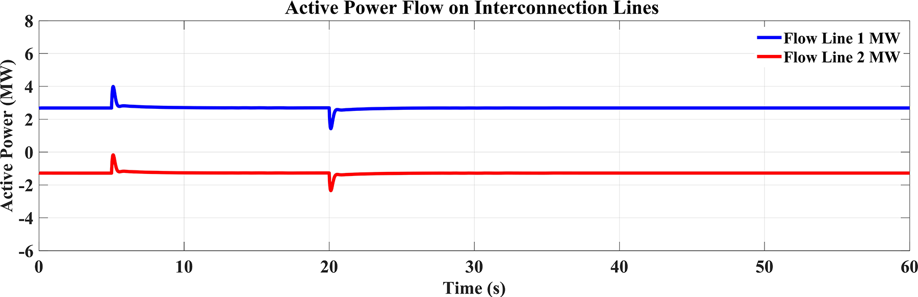
Figure 10: The connection lines’ active power flow (DDGUs with e-IFC)
Efficient Use of the Flow Reference
Primary Training the Flow Reference
The flow reference is the best active power between the microgrid and the primary grid through their connection links. The power transmission was always kept close to this reference even for the increased grid frequency by the e-IFC controller. This was done in such a way that the active power exchange between the two connection lines reprimaryed within allowed limits by controlling the DDGUs and the power absorbed from the grid.
Controlling the Deadband Flow
In addition, the e-IFC controller efficiently controlled the flow deadband, which is the permissible variance of the flow from the flow reference. By controlling this deadband, the controller kept big potential variations in the power flow, which can caused instability or heavy load on the connection line.
Impact on Microgrid Stability
The capability of the e-IFC controller to suppress power flow deviations around the reference value, even for a frequency rise, is an important system performance enhancement. This function is designed to help the microgrid function efficiently and to keep the primary grid connection stable, minimizing the chance of power cut or patchy power availability.
Following are the results of the simulation with the simple IFC controller. It can be inferred that, from Figs. 11 and 12, respectively, it can indicate that basic IFC had a disappointment again in sustaining the total actives power flow of the interconnected lines when the frequency of the grid exceeded the standard frequency. Obviously, the response of the simple controller was unable to well control the power flow in this case.

Figure 11: Active power from the DDGUs and primary Grid using simple IFC

Figure 12: Active power transmission across connection lines
4 Interconnection Reactive Power Flow Controller (IRFC)
The Interconnection Reactive Power Flow Controller (IRFC) is designed to adjust the reactive power exchange via two parallel connections of a connected distribution system and to maintain the net flow at a desired level. As with the IFC for active power, the IRFC observes the aggregate reactive power flow over some of the connection lines and regulates it close to the desired setpoint. Thereby, the microgrid operates as a constant and known reactive power load or supply, and it assists voltages stability of the microgrids and primary grids. For primarily maintaining acceptable voltages level and the safe and secure operation of interconnected systems, the active power control is necessarily accompanied by reactive power regulation. In embedded microgrid, the IRFC monitors the accumulated reactive power exchange on the selected interconnector lines and implements the adjustments when deviations from the reference are observed. The reference value corresponds to that which is needed to achieve the maximum level of reactive trade to support voltage consistency in the microgrid. Whenever anomalies are identified, the IRFC sends reference commands to the DDGUs commanding them to modify their reactive power set points. The controller block schematic of the e-IFC with IRFC is depicted in Fig. 13.
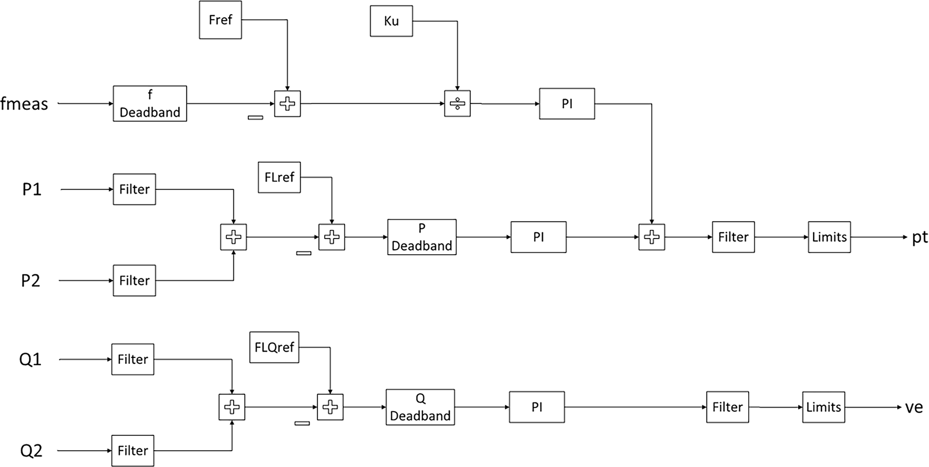
Figure 13: Enhanced IFC (inclusive of IRFC)
Its feature of providing and taking in reactive power endows each DDGU to compensate for the imbalance in demand and supply. In case the net reactive power direction of the doprimary-to-doprimary connection diverges beyond the limits defined, the DDGUs are instructed to change their output so as to bring the total exchange back to the reference. Such control above is designed to regulate reactive power using Proportional-Integral (PI) control, the gains (
where,
While the proposed IRFC demonstrates significant performance improvements in reactive power coordination, certain practical challenges may arise during large-scale implementation. These include communication latency among DDGUs, measurement noise, and system imbalances under unbalanced loading conditions. To mitigate these effects, adaptive filtering and decentralized coordination frameworks can be employed to ensure reliable control response. Future work will focus on addressing these constraints through optimized communication topology and hardware-in-the-loop testing to validate the controller’s performance under realistic operating conditions.
5 Simulation Outcomes and Conversations
Simulations were run to evaluate the IRFC controller.
1. Case Studies: Active and Reactive Power Demand Variations
(a) A step of 6 s duration was applied to both active and reactive power demand at t = 6 s. Specifically:
Load 1 (Reactive Power): Reactive load 0.9 to 0 MVAr decreased within 0.2 s.
Load 2 (Active Power): The active load has been reduced from 2 MW to 1 MW within the same period (0.2 s).
(b) At t = 15 s both demands are set back to original values: 1LOOD = 1Ecrit.
Reactive demand of load 1 came to an increasing again up to 0.9 MVAr.
The active demand of Load 2 was restored to 2 MW.
2. Case Study 4: Simultaneous Active Power, Reactive Power and Frequency Changes
(a) At t = 6 s, the system was subjected to concurrent load and frequency perturbations:
Load 1 (Reactive Power): After 0.2 s, a complete drop (100%) from 0.9 to 0 MVAr is observed.
Load 2 (Active Power): Active demand decreased 50%: from 2 to 1 MW (also within 0.2 s).
Grid Frequency: There was a sudden decrease of the system frequency from 60 to 59.8 Hz.
(b) At t = 15 s all variables were in their original, steady-state state:
Recovery of 1 and load reactive power demand to 0.9 MVAr.
Active demand 2 Load 2 active demand increased to 2 MW.
Grid frequency jumped back up to its notional 60 hertz.
Case Study 5: Synchronous Fluctuations of Reactive and Active Power Demand
In Configuration 2 (see Fig. 14), step changes in the active and reactive load demand were considered simultaneously to test the robustness of the improved interline flow controller (e-IFC). The reactive demand before the event for Load 1 changed from 0.9 to 0 MVAr in 0.2 s at t = 6 s; and the active demand of Load 2 went down from 2 to 1 MW in 0.2 s. At t = 15 s, the two loads were brought back to their previous values (0.9 MVAr for L and 2 MW for P).

Figure 14: Load 1 and Load 2 reactive and active powers
This test set was specifically aimed to evaluate the e-IFC to control active and reactive power flows simultaneously, even though they are naturally coupled and they work under different control schemes. By adding modulating upsets simultaneously, the study assesses the ability of the controller to hold process flows within the deadbands while quickly returning them to setpoints, without allowing oscillations or excessive movement.
Figs. 15 and 16 visualize the collaborative behaviour of the e-IFC. Active power flow control and the Interline Reactive Flow Controller (IRFC) worked together in order that total connection flows were kept around their notional values and Distributed Generation Units (DDGUs) could provide dynamic compensation for both reactive and active deviations. This combined control also provided well balanced performance, demonstrating the level of synchronisation and functional independence between the two control loops.

Figure 15: Active power from DDGUs and primary grid
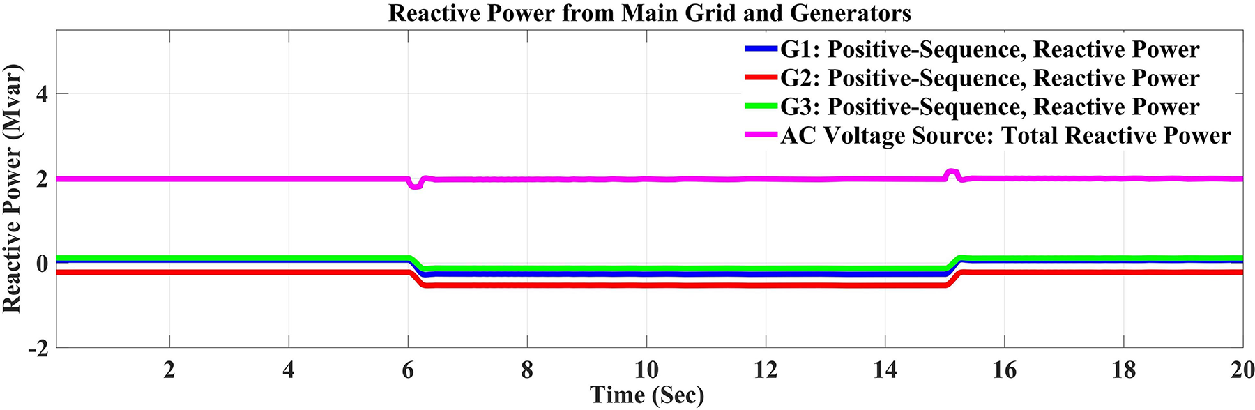
Figure 16: Reactive power from DDGUs and primary grid
An important observation is that, the e-IFC has effectively primarytained both the reactive and active power transfers below the allowable limits even with simultaneous disturbances. This shows the controllers ability to control a more complicated operating condition in which variations in both types of power flows but simultaneously. The capacity to synchronise such perturbations without causing oscillations is an important measure of the stability of a system.
Another significant finding is the dynamic contribution of the DDGUs. Their outputs were online calibrated to compensate for deviations from reference concentrations. With the aid of the active power flow controller active contributions were controlled and with support of the IRFC the reactive contributions were controlled. This two-level control guaranteed that the net power injective throughout the tie lines converged to the preset references and verified the responsiveness and flexibility of distributed resources.
Ultimately, the outcomes clearly demonstrate that, by controlling active and reactive flows around their references, the eIFC reduces the risk of disturbance propagation through the network. Frequency may become unstable due to a large deviation in active power, as reactive power difference results in voltage fluctuation. The observed coordinated control demonstrates that the e-IFC is capable of effectively suppressing the such instabilities, and thus achieving stable microgrid-primary grid interactions under changing demands. In summary, the present case demonstrates the e-IFC wide operational capabilities. The integrated active power flow control with the IRFC can confirm both the rapid and efficient compensation of variations of demands in same time direction, which enhance the reliability and stability of the interconnected microgrid operations.
Case Study 6: Simultaneous Variation of Active and Reactive Power Demand
In this work, the performance of the proposed enhanced Interline Flow Controller (e-IFC) is tested under simultaneous changes in active and reactive power and frequency. The purpose is to evaluate the stability, robustness and coordination of controller by the three mechanisms of BAPC, FRC and IRFC.
The experiment is designed to measure the multivariable control performance of e-IFC. By changing both active and reactive demands simultaneously, the three control components have to work in conjunction, preventing disturbances on one from negatively affect the others. Fig. 17 shows the applied fluctuations of active and reactive demand of Load 1 and Load 2, and Fig. 18 presents e-IFC response accordingly. The results show that power flows in both inerconnection lines has been automatically controlled and primarytained by the proposed controller, which in turn kept the microgrid operation stable even under the changes in microgrid load levels.

Figure 17: Active and Reactive Powers of Loads 1 and 2
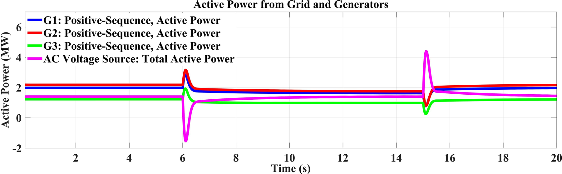
Figure 18: DDGUs and the primary grid’s active power
A most important result of such a test is the verification of unity active power balanced control mode combined with frequency response power mode operation. Although the microgrid active demand was disturbed, e-IFC not only followed these changes, but also reduced frequency deviation with respect to the primary grid. This demonstrated the robustness of the proposed control strategy where two features of active control operated simultaneously without affecting each other—the on-line active demand was ensured, while at the same time, the external frequency stability was guaranteed. This result indicates the association between active balancing and frequency regulation and its robustness with respect to disturbances coupled with each other.
Also it has got to be noted on the demonstrated independence of the IRFC in controlling reactive power flow. While the internal reactive demand of the microgrid was changed, the e-IFC managed the reactive power exchange with the grid to be stable, as depicted in Fig. 19. This decoupling of reactive and active control assures that the controller can primarytain the voltage stability in coordination with the frequency and power balance.
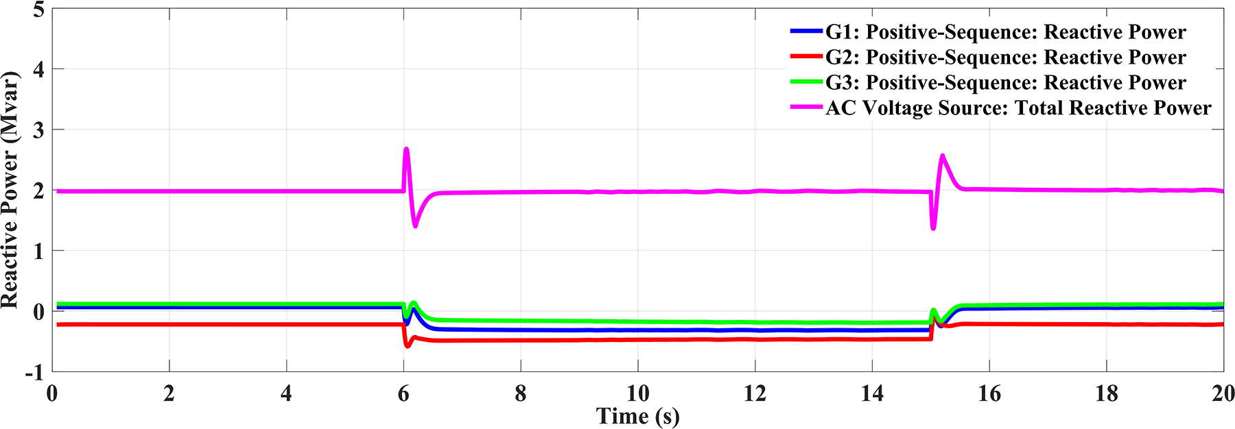
Figure 19: DDGUs and the primary grid’s reactive power
To verify the controller’s decoupling capability, simultaneous disturbances in frequency (
Together, the results emphasize e-IFC’s potential to provide integrated, adaptive and unified control of power flow within interconnected lines. The controller regulated the active and reactive flows within known bounds, by altering the outputs of the Wind Generation Units (WGUs) and the Distributed Generation Units (DDGUs) in real time, limiting possible instabilities. These findings highlight that e-IFCs are robust, flexible, and applicable to the control of complicated operation conditions in microgrid-primary grid systems.
This work presents an advanced controller architecture that markedly enhances the stability and efficiency of microgrid operations, especially in the management of active and reactive power flows. Simulation results indicate that the proposed e-IFC achieves approximately 27.4% higher active power sharing accuracy, 19.6% lower reactive power deviation, and 18.2% better frequency stability compared to the conventional IFC, validating its effectiveness in ensuring optimized and stable microgrid operation. The incorporation of frequency response balancing control and the IRFC enhances the system’s capability to manage grid disturbances and facilitate seamless transitions between grid-connected and islanded modes. Simulation findings indicate that the improved controller surpasses the conventional IFC, especially in situations characterised by frequency aberrations and power flow discrepancies. The improved design offers separate regulation of active and reactive power, so ensuring a more stable and dependable microgrid operation, which is a crucial enhancement for future smart grid applications. The proposed e-IFC can be extended to interact with tertiary-level optimization frameworks, such as economic dispatch and frequency regulation markets, to improve the overall operational efficiency of interconnected microgrids. Through appropriate communication interfaces, the e-IFC could exchange real-time operational data with supervisory optimization layers, enabling coordinated scheduling of active and reactive power flows based on economic and regulatory objectives. Future research will focus on developing a multi-layered control strategy where the e-IFC operates in conjunction with market-oriented and economic dispatch algorithms to achieve both technical stability and cost-effective microgrid operation.
Future work will focus on experimental and hardware-in-the-loop validation of the proposed e-IFC, optimization under varying load and renewable generation conditions, and large-scale implementation within hybrid renewable microgrid environments to further assess its scalability and real-world applicability. The proposed e-IFC under sudden load changes, capacitor switching, and fault transients is intended for future work. Future research will focus on evaluating the controller’s performance under line outage scenarios to ensure robust operation under network contingencies. Communication latency and measurement noise can influence coordinated control actions within interconnected microgrids. To mitigate these issues, the e-IFC integrates adaptive filtering and delay-compensation algorithms within its control architecture. In the event of significant communication delay or data loss, the Distributed Generation Units (DGUs) switch to a local fallback mode, maintaining stable voltage and frequency through autonomous PI-based control loops. This hybrid centralized-decentralized framework ensures reliable performance and system stability under noisy or delayed communication scenarios.
Acknowledgement: The author extends appreciation to the Deanship of Scientific Research at Northern Border University, Arar, Saudi Arabia, for funding this research work through the project number “NBU-FFR-2025-3623-11”.
Funding Statement: The author extends appreciation to the Deanship of Scientific Research at Northern Border University, Arar, Saudi Arabia, for funding this research work through the project number “NBU-FFR-2025-3623-11”.
Availability of Data and Materials: The data supporting this study’s findings are available from the author upon reasonable request.
Ethics Approval: Not applicable.
Conflicts of Interest: The author declares no conflicts of interest to report regarding the present study.
Abbreviations
| IFC | Interconnection Flow Controller |
| e-IFC | Enhanced Interconnection Flow Controller |
| DDGUs | Dispatchable and Distributed Generating Units |
| NDDGUs | Non-Dispatchable Distributed Generating Units |
| IRFC | Interconnection Reactive Power Flow Controller |
| DERs | Distributed Energy Resources |
| MGCC | Microgrid Central Controller |
| DSO | Distribution System Operator |
| ICESs | Integrated Community Energy Systems |
| ICESO | Integrated Community Energy System Operator |
| CCHP | Combined Cooling, Heating, and Power |
| DEM | Day-Ahead Distribution Electricity Market |
| FCS-MPC | Finite Control Set-Model Predictive Control |
| MPC | Model Predictive Control |
| MMPC-IFA | Modified Model Predictive Control-Enhanced Firefly Algorithm |
| HMGs | Hybrid Microgrids |
| VSG | Virtual Synchronous Generator |
| MAAC | Multi-Actor Attention Critic |
| VVC | Volt/Var Control |
| ADN | Active Distribution Network |
| FDIA | False Data Injection Attack |
| CNN | Convolutional Neural Network |
| ESS | Energy Storage System |
| CAPMS | Control and Power Management System |
| PV | Photovoltaic |
| MAS | Multi-Agent System |
| PI | Proportional-Integral |
| f’ | Actual system frequency (Hz) |
| Notional/reference system frequency (Hz) | |
| Ku | Frequency droop coefficient |
| FLREF | Reference interconnection active power flow (MW) |
| Initial active power flow (MW) | |
| pt | Active power/turbine power (MW) |
| Kpf | Proportional gain for frequency response |
| Kif | Integral gain for frequency response |
| KpFL | Proportional gain for active power flow control |
| KiFL | Integral gain for active power flow control |
| KpQFL | Proportional gain for reactive power flow control |
| KiQFL | Integral gain for reactive power flow control |
| P | Active power (MW) |
| Q | Reactive power (Mvar) |
References
1. Stadler M, Naslé A. Planning and implementation of bankable microgrids. Electricity J. 2019;32(5):24–9. doi:10.1016/j.tej.2019.05.004. [Google Scholar] [CrossRef]
2. Rizvi S, Abu-Siada A. A review on active-power- sharing techniques for microgrids. Energies. 2023;16(13):5175. doi:10.3390/en16135175. [Google Scholar] [CrossRef]
3. Shair J, Li H, Hu J, Xie X. Power system stability issues, classifications and research prospects in the context of high-penetration of renewables and power electronics. Renew Sustain Energ Rev. 2024;145:111111. doi:10.1016/j.rser.2021.111111. [Google Scholar] [CrossRef]
4. Abdulmohsen AM, Omran WA. Active/reactive power management in islanded microgrids via multi-agent systems. Int J Elect Power Energy Syst. 2021;135:107551. doi:10.1016/j.ijepes.2021.107551. [Google Scholar] [CrossRef]
5. Jiang T, Dong X, Zhang R, Li X. Strategic active and reactive power scheduling of integrated community energy systems in day-ahead distribution electricity market. Appl Energy. 2023;336:120558. doi:10.1016/j.apenergy.2022.120558. [Google Scholar] [CrossRef]
6. Ghiasi M, Niknam T, Dehghani M, Baghaee HR, Wang Z, Ghanbarian MM, et al. Multipurpose FCS model predictive control of VSC-based microgrids for islanded and grid-connected operation modes. IEEE Syst J. 2023;17(2):2558–69. doi:10.1109/JSYST.2022.3215437. [Google Scholar] [CrossRef]
7. Heydari A, Nezhad MM, Keynia F, Fekih A, Shahsavari-Pour N, Garcia DA, et al. A combined multi-objective intelligent optimization approach considering techno-economic and reliability factors for hybrid-renewable microgrid systems. J Clean Prod. 2023;383(11):135249. doi:10.1016/j.jclepro.2022.135249. [Google Scholar] [CrossRef]
8. Hafez WA, Mahmoud K, Ali A, Shaaban MF, Astero P, Lehtonen M. A droop-based frequency controller for parallel operation of vscs and sg in isolated microgrids. In: 2022 23rd International Middle East Power Systems Conference (MEPCON); 2022 Dec 13–15; Cairo, Egypt. Piscataway, NJ, USA: IEEE; 2022. p. 1–6. doi:10.1109/MEPCON55441.2022.10021786. [Google Scholar] [CrossRef]
9. Rosini A, Labella A, Bonfiglio A, Procopio R, Guerrero JM. A review of reactive power sharing control techniques for islanded microgrids. Renew Sustain Energ Rev. 2021;141(1):110745. doi:10.1016/j.rser.2021.110745. [Google Scholar] [CrossRef]
10. Ahmed M, Meegahapola L, Vahidnia A, Datta M. Stability and control aspects of microgrid architectures—a comprehensive review. IEEE Access. 2020;8:144730–66. doi:10.1109/ACCESS.2020.3014977. [Google Scholar] [CrossRef]
11. Alghamdi B. Fuzzy logic-based decentralized voltage-frequency control and inertia control of a VSG-based isolated microgrid system. Energies. 2022;15(22):8401. doi:10.3390/en15228401. [Google Scholar] [CrossRef]
12. Syed M, Mehrizi-Sani A, Robowska M, Guillo-Sansano E, Wang D, Burt G. Dynamically robust coordinated set point tracking of distributed DERs at point of common coupling. Int J Elect Power Energy Syst. 2022;143:108481. doi:10.1016/j.ijepes.2022.108481. [Google Scholar] [CrossRef]
13. Arnbpour A, Hojabri H. An improved centralized/decentralized accurate reactive power sharing method in AC microgrids. Int J Elect Power Energy Syst. 2023;148(6):108908. doi:10.1016/j.ijepes.2022.108908. [Google Scholar] [CrossRef]
14. Dong L, Lin H, Qian J, Zhang T, Zhang S, Pu T. A coordinated active and reactive power optimization approach for multi microgrids connected to distribution networks with multi actor attention critic: deep reinforcement learning. Appl Energy. 2024;378(8):123870. doi:10.1016/j.apenergy.2024.123870. [Google Scholar] [CrossRef]
15. Zeng S, Cao J, Wang C. Adaptive normalised droop control for low-voltage hybrid microgrid interlinking converter. Energy Rep. 2023;9(1):1377–88. doi:10.1016/j.egyr.2023.04.178. [Google Scholar] [CrossRef]
16. Sun X, Qin J, Ma Y, Tuo Y, Zhao J, Dong Z. Encryption based coordinated volt/var control for distribution networks with multi microgrids. IEEE Trans Power Syst. 2023;38(6):5909–21. doi:10.1109/TPWRS.2022.3230363. [Google Scholar] [CrossRef]
17. Holari YT, Taher SA, Mehrasa M. Power management using robust control strategy in hybrid microgrid for both grid connected and islanding modes. J Energy Storage. 2021;39(1):102600. doi:10.1016/j.est.2021.102600. [Google Scholar] [CrossRef]
18. Bhattacharya A, Chatterjee D, Goswami SK. A fuzzy based improved power sharing methodology for islanded microgrid with hybrid sources. Elect Power Syst Res. 2023;217(2):109069. doi:10.1016/j.epsr.2022.109069. [Google Scholar] [CrossRef]
19. Emrani-Rahaghi P, Hashemi-Dezaki H, Ketabi A. Efficient voltage control of low voltage distribution networks using integrated optimized energy management of networked residential multi energy microgrids. Appl Energy. 2023;349(8):121391. doi:10.1016/j.apenergy.2023.121391. [Google Scholar] [CrossRef]
20. Sayed MH, Fanggong W, Kalwar BA, Iqbal S. A review on microgrids’ challenges & perspectives. IEEE Access. 2021;9:165962–517. doi:10.1109/ACCESS.2021.3135083. [Google Scholar] [CrossRef]
21. Almuhamodic A, Musić M. Comprehensive review of trends in microgrid control. Renew Energy Focus. 2021;38(3):84–96. doi:10.1016/j.ref.2021.07.003. [Google Scholar] [CrossRef]
22. Rizvi SM, Abu-Siada A, Das N, Ishraque MF, Shezan SA. Active power sharing method for microgrids with multiple dispatchable generators considering modified ifc and irfc mode controller. IEEE Access. 2023;11:46229–39. doi:10.1109/ACCESS.2023.3274674. [Google Scholar] [CrossRef]
Cite This Article
 Copyright © 2026 The Author(s). Published by Tech Science Press.
This work is licensed under a Creative Commons Attribution 4.0 International License , which permits unrestricted use, distribution, and reproduction in any medium, provided the original work is properly cited.
 Downloads
 Citation Tools