
 Login
Login Register
 Submit a Paper
 Propose a Special lssue
 Open Access
ARTICLE

Transient Thermo-Hydraulic Behavior of a Thermocline Thermal Energy Storage Tank: A CFD Investigation
1 Laboratory of Energy Engineering and Materials (LEEM), Faculty of Sciences and Technologies, Sultan Moulay Slimane University, Beni Mellal, Morocco
2 LMPEQ, National School of Applied Sciences, Safi, Morocco
3 EnR2E Laboratory, National Center for Studies and Research on Water and Energy, Cadi Ayyad University, Marrakesh, Morocco
4 L3G, Faculty of Science and Technology Cadi Ayyad University, Marrakesh, Morocco
* Corresponding Author: Abdellah Idrissi. Email:
(This article belongs to the Special Issue: Next-Generation Solar Thermal and Energy Storage Systems: Modeling, Optimization and Performance)
Energy Engineering 2026, 123(10), 16 https://doi.org/10.32604/ee.2026.083896
Received 13 April 2026; Accepted 16 June 2026; Issue published 30 August 2026
 View Full Text
 Download PDF
Abstract
This study numerically investigates the influence of inlet–outlet arrangement on the thermo-hydraulic performance of a thermocline thermal energy storage (TES) tank using three-dimensional transient CFD simulations in ANSYS Fluent. Four different inlet–outlet configurations were analyzed under identical discharge conditions to evaluate their effects on thermal stratification, discharge efficiency, and internal flow behavior. The numerical model was developed using the continuity, momentum, and energy equations with the Boussinesq approximation and validated against reference experimental data with deviations below 5%. The results showed that the inlet–outlet arrangement significantly affects thermocline evolution and thermal mixing inside the storage tank. Among the investigated configurations, Configuration 2 exhibited the most favorable thermo-hydraulic behavior, improving thermal stratification and discharge efficiency by approximately 18%–22% compared with the baseline configuration because of reduced recirculation intensity and weaker thermal mixing. Although Configuration 2 produced a moderate increase in pressure drop and pumping power, the improved thermal performance justified the associated hydraulic penalty. The obtained findings indicate that relatively simple modifications in inlet–outlet positioning can improve thermocline preservation and thermal energy recovery in compact TES systems.Graphic Abstract
Keywords
The rapid expansion of renewable energy systems and the increasing demand for energy-efficient thermal management solutions have highlighted the strategic importance of thermal energy storage (TES) technologies in improving energy flexibility and overall energy efficiency [1,2]. Additional studies also emphasized the role of TES systems in renewable energy integration and thermal management applications [3,4]. Among the different TES technologies, thermocline thermal energy storage tanks have attracted considerable attention because of their simple design, reduced cost, and high storage capacity [5,6]. Experimental and numerical investigations also demonstrated their suitability for solar thermal and domestic hot water applications [7,8].
These systems are widely employed in solar thermal applications and domestic hot water systems, where maintaining strong thermal stratification is essential for preserving temperature layering and improving thermal storage performance [9,10]. Additional studies also reported the importance of thermocline preservation for improving discharge efficiency and reducing exergy losses [11–13]. Thermal stratification in TES tanks refers to the formation of distinct hot and cold fluid layers separated by a thermocline region. A well-preserved thermocline improves storage efficiency, enhances discharge performance, and reduces exergy losses [9]. However, the quality of thermal stratification is strongly affected by inlet flow characteristics, buoyancy-driven recirculation, tank geometry, and internal flow disturbances [14–18]. Inappropriate flow arrangements may intensify thermal mixing between hot and cold regions, leading to thermocline degradation and reduced discharge efficiency [17,18].
In recent years, Computational Fluid Dynamics (CFD) has become an effective tool for analyzing transient thermo-hydraulic behavior in thermal storage systems. CFD enables detailed investigation of velocity fields, temperature distributions, thermocline evolution, and internal mixing mechanisms under different operating conditions. Previous CFD investigations analyzed thermal stratification and transient flow behavior in TES tanks through modifications in tank geometry and flow control strategies [19]. Additional thermo-fluid simulations were also performed using advanced numerical approaches for TES applications [20]. Advanced thermal stratification enhancement techniques, including novel inlet systems [5], radial plate-type diffusers [15], and perforated inlet structures with dynamic flow control [9], were investigated to reduce jet-induced mixing and improve thermocline preservation.
Although several studies investigated thermocline enhancement techniques, fewer studies systematically examined the thermo-hydraulic influence of simplified inlet–outlet positioning under identical discharge conditions. Moreover, several previous investigations primarily focused on thermal performance without simultaneously evaluating hydraulic penalties such as pressure drop and pumping power [9]. Nevertheless, simplified inlet–outlet configurations remain attractive for compact and low-cost TES applications because of their reduced manufacturing complexity, lower maintenance requirements, and easier implementation.
In this context, the present study investigates the transient thermo-hydraulic behavior of a thermocline TES tank subjected to four different inlet–outlet arrangements using three-dimensional CFD simulations in ANSYS Fluent. The numerical model is developed by solving the continuity, momentum, and energy equations with the Boussinesq approximation to account for buoyancy effects. The model is first validated against reference experimental data and verified through a mesh independence analysis.
A comprehensive thermo-hydraulic assessment is then performed using key performance indicators, including thermal stratification, discharge efficiency, average outlet temperature, Richardson number, pressure drop, and pumping power. Special attention is given to the interaction between buoyancy-driven flow structures, recirculation intensity, and thermocline evolution during the discharge process. The present work provides a combined CFD-based evaluation of thermal and hydraulic performance under identical operating conditions and offers practical design insights for improving compact thermocline TES systems used in solar thermal and domestic hot water applications.
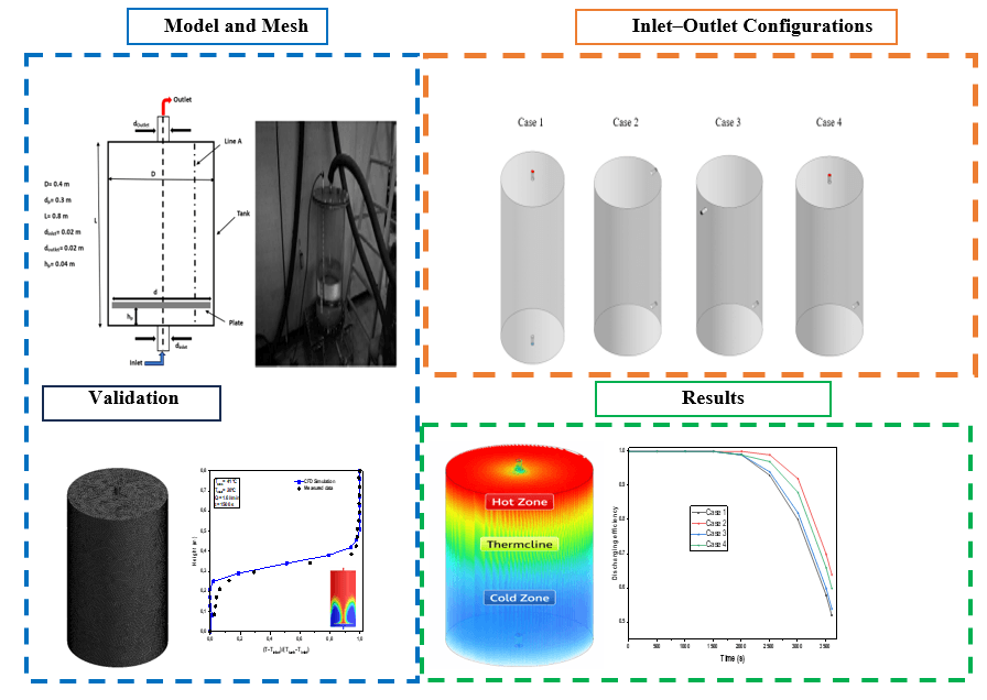
The three-dimensional computational domain of the thermocline thermal energy storage (TES) tank, along with the investigated inlet–outlet arrangements, is presented in Fig. 1. The studied TES tank consists of a vertical cylindrical storage vessel designed to evaluate the effect of flow arrangement on thermal stratification and discharge performance under transient operating conditions. The tank geometry was defined according to the experimental reference configuration used for model validation, with dimensions selected to ensure realistic flow and thermal behavior [21].

Figure 1: Overview of the CFD methodology and key results for the thermocline TES tank.
Four different inlet–outlet configurations were investigated under identical discharge conditions to evaluate their influence on internal flow structure, thermocline evolution, and thermo-hydraulic performance. The investigated configurations differ in the relative positions of the inlet and outlet ports, which directly affect flow penetration, buoyancy-driven recirculation, and thermal mixing inside the storage tank. The geometrical characteristics of the investigated configurations are summarized in Table 1.

To validate the numerical model, the predicted temperature distributions were compared with available experimental measurements obtained from the reference TES system [21]. A structured computational mesh was generated to accurately capture temperature gradients, thermocline displacement, and local recirculation phenomena during the transient discharge process. The adopted CFD framework enabled detailed analysis of thermal stratification, discharge efficiency, and hydraulic behavior for all investigated configurations (Fig. 2).

Figure 2: Three-dimensional TES tank model and investigated inlet–outlet configurations under discharge conditions.
The numerical simulations of the thermocline thermal energy storage (TES) tank were performed by solving the fundamental governing equations of fluid flow and heat transfer, including the continuity, momentum, and energy equations. The storage fluid was assumed to be incompressible and Newtonian, while thermal buoyancy effects were incorporated using the Boussinesq approximation. Heat transfer inside the tank was governed by the combined effects of natural convection and thermal conduction, whereas thermal radiation was neglected due to its limited influence under the investigated operating conditions [22–26]. The following assumptions were adopted in the present numerical model:
• The fluid is incompressible and Newtonian;
• The flow is transient and laminar;
• Thermal buoyancy is modeled using the Boussinesq approximation;
• Heat transfer occurs by conduction and convection only;
• Thermal radiation effects are neglected;
• Viscous dissipation effects are neglected;
• The tank walls are considered adiabatic unless otherwise specified.
Under these assumptions, the governing equations were discretized and solved numerically in ANSYS Fluent [27–29] using the finite volume method (FVM), originally proposed by Patankar and Spalding [30]. The governing equations were solved in their transient three-dimensional form to capture thermocline evolution and buoyancy-driven flow behavior during the discharge process.
1. Continuity equation
2. Momentum equations
3. Energy equation
4. Boussinesq validity
The Boussinesq approximation was considered valid because the maximum temperature difference inside the TES tank remained below 25 K, resulting in relatively small density variations within the storage fluid. Under these conditions, buoyancy effects can be accurately represented without solving the fully compressible form of the governing equations.
2.3 Thermo-Hydraulic Performance Indicators
The thermo-hydraulic performance of the thermocline thermal energy storage (TES) tank was assessed using several key performance indicators that quantify thermal stratification quality, discharge effectiveness, and flow behavior. These parameters provide a comprehensive evaluation of the tank’s ability to preserve thermal energy, maintain a stable thermocline, and deliver useful thermal output during discharge.
Thermal stratification quality is commonly characterized by the stratification number, which reflects the sharpness of the vertical temperature gradient inside the storage tank. A higher stratification number indicates better preservation of thermal layering and reduced mixing between hot and cold regions. The discharging efficiency evaluates the capability of the TES tank to recover useful thermal energy during operation. In addition, the Richardson number is used to characterize the relative importance of buoyancy forces compared with inertial effects, which directly influences thermocline stability.
Hydraulic performance was also assessed through pressure drop and pumping power, which are essential indicators of flow resistance and operational energy consumption. Together, these parameters provide a reliable basis for comparing the overall performance of the investigated inlet–outlet configurations and identifying the most effective design for thermocline preservation and discharge enhancement [31].
The Richardson number characterizes the balance between buoyancy and inertial forces. Higher Richardson numbers indicate stronger buoyancy dominance and improved thermocline stability.
The stratification number quantifies the sharpness of the vertical thermal gradient inside the storage tank. Higher values indicate better thermal layer preservation and reduced thermal mixing.
The discharge efficiency reflects the ability of the TES tank to deliver thermally useful energy during discharge before significant degradation of outlet temperature occurs.
The calculated Reynolds number was approximately Re ≈ 1.7 × 10³, which remains within the laminar or weak transitional regime typically reported for low-flow thermocline TES systems. The flow inside the tank is predominantly governed by buoyancy effects and weak inertial forces, which supports the use of the laminar flow assumption. Although localized recirculation zones develop during discharge, the overall flow structure remained predominantly buoyancy-driven and stratification-controlled rather than fully turbulent.
Although the Reynolds number approaches the lower limit of the transitional regime, the flow inside the TES tank remains strongly influenced by buoyancy effects, as confirmed by the relatively high Richardson numbers obtained for all investigated configurations (Ri = 4.79–5.35). Under these conditions, buoyancy forces dominate over inertial effects and govern thermocline stability and flow development. Therefore, the overall flow behavior remains primarily stratification-controlled rather than turbulence-controlled. While localized transitional structures may appear near the inlet region because of jet penetration and recirculation, their influence on the global thermo-hydraulic behavior is expected to remain limited. Consequently, the laminar flow model is considered appropriate for the investigated low-flow operating conditions. Future studies may employ transitional or low-Reynolds-number turbulence models to further assess local flow structures and mixing phenomena.
A mesh independence study was carried out to determine the optimal grid resolution for accurate and computationally efficient simulations of the thermocline thermal energy storage (TES) tank. Three structured meshes with different element densities were generated to evaluate their influence on temperature distribution and thermocline evolution. The tested grids consisted of Mesh 1 with 796,715 elements, Mesh 2 with 1,092,343 elements, and Mesh 3 with 1,550,532 elements. All meshes showed satisfactory quality, with average skewness values ranging from 0.202 to 0.204 and average orthogonal quality between 0.7945 and 0.7958, confirming their suitability for accurate and stable CFD simulations (Fig. 3 and Table 2).

Figure 3: Structured mesh configurations used for the mesh independence study of the TES tank.

The effect of mesh refinement on the predicted temperature profile was also analyzed. The average tank temperatures obtained for Mesh 1, Mesh 2, and Mesh 3 were 307.197, 306.873, and 306.552 K, respectively. Although Mesh 3 provided slightly improved numerical accuracy, the relative temperature variation between Mesh 2 and Mesh 3 remained below 0.10%, indicating negligible sensitivity to additional mesh refinement. Therefore, Mesh 2 was selected for all subsequent simulations because it provided an appropriate compromise between numerical accuracy and computational cost (Fig. 4) [32].

Figure 4: Effect of mesh refinement on the vertical temperature profile inside the TES tank.
To further quantify mesh sensitivity, a comparative error analysis was performed between successive grid refinements. The relative error between Mesh 1 and Mesh 2 was 0.106%, while the difference between Mesh 2 and Mesh 3 was only 0.105%. The maximum deviation observed between the coarsest and finest meshes remained below 0.21%. These results confirm that the numerical predictions are practically independent of further mesh refinement and support the selection of Mesh 2 as an optimal compromise between computational cost and numerical accuracy as shown in Table 3.

2.5 Numerical Simulations Framework
Transient three-dimensional CFD simulations were performed using ANSYS Fluent 19.R3 by solving the continuity, momentum, and energy equations with the Boussinesq approximation to account for buoyancy effects. Cold water entered the TES tank through a velocity inlet with a constant velocity of 0.085 m·s−1 and a temperature of 293.15 K, while the outlet was modeled as a pressure outlet under atmospheric conditions. The initial tank temperature was set to 314.15 K. No-slip and adiabatic boundary conditions were applied at the tank walls.
Pressure-velocity coupling was achieved using the SIMPLE algorithm, while second-order upwind discretization schemes were employed for the momentum and energy equations to improve numerical accuracy. Gravity was applied along the vertical direction to capture buoyancy-driven flow behavior. Hybrid initialization was used before transient calculations.
A fixed time step of 10−3 s was adopted for all simulations following preliminary stability and convergence tests. Convergence was considered achieved when the residuals fell below 10−5 for continuity and momentum equations and 10−8 for the energy equation (Table 4).

The present study focuses on low-flow operating conditions representative of domestic hot water and compact TES applications, where laminar or weak transitional flow regimes are commonly observed. Nevertheless, turbulence effects may become significant at higher flow rates or in large-scale TES systems. Future investigations should therefore include advanced turbulence modeling under broader operating conditions.
The selected operating condition was intentionally chosen to represent a typical low-flow discharge regime encountered in domestic hot water and compact TES applications. The objective was to isolate the influence of inlet–outlet arrangement on thermocline evolution and thermo-hydraulic performance while avoiding additional complexities associated with varying operating parameters. Although the conclusions are limited to the investigated operating range, the adopted approach provides useful insight into the relative performance of the different configurations.
The adopted numerical model was selected to capture the dominant thermo-hydraulic mechanisms governing thermocline evolution in the TES tank, including buoyancy-driven flow, thermal stratification, and transient heat transfer. The use of a three-dimensional transient CFD approach with the Boussinesq approximation allows accurate representation of density variations induced by temperature differences while maintaining reasonable computational cost. Considering the investigated low-flow operating conditions and the calculated Reynolds number, the adopted modeling assumptions provide an appropriate framework for comparative evaluation of the investigated inlet–outlet configurations.
3.1 Verification of the Simulation Model
To evaluate the reliability of the developed CFD model, the predicted dimensionless temperature profile along the tank height during discharge was compared with reference experimental data at t = 1500 s [21]. The comparison showed reasonable agreement between numerical and experimental results, with deviations remaining below 5% over most of the tank height. These results indicate that the adopted numerical methodology is capable of reproducing the transient thermo-hydraulic behavior and thermocline evolution inside the TES tank with acceptable accuracy.
The agreement between numerical and experimental results suggests that the governing equations, boundary conditions, and transient solution strategy appropriately represent the coupled effects of buoyancy-driven flow, thermal stratification, and heat transfer during the discharge process. The validated model therefore provides a suitable basis for analyzing the influence of inlet–outlet arrangements on temperature distribution, thermocline preservation, and discharge performance.
Although the reference experimental configuration included internal plates intended to improve thermal stratification, the present validation primarily aimed to assess the capability of the CFD model to reproduce the dominant thermo-hydraulic mechanisms governing transient thermocline evolution under buoyancy-driven flow conditions. Since the governing transport phenomena remain similar, the observed agreement between numerical and experimental temperature profiles is considered acceptable for validating the adopted numerical approach.
Fig. 5 presents the comparison between the numerical and experimental dimensionless temperature profiles along the TES tank height during the discharge process at t = 1500 s.

Figure 5: Comparison between numerical and experimental dimensionless temperature profiles during discharge process at t = 1500 s [21].
Some discrepancies were observed near the lower region of the tank and within the thermocline zone, particularly in the vertical region close to the inlet. These deviations may be attributed to differences between the experimental configuration and the present numerical setup, as well as uncertainties associated with transient buoyancy-driven mixing and local recirculation phenomena. The experimental temperature measurements were extracted along the central vertical axis of the TES tank, consistent with the reference experimental study [21].
Although the present validation demonstrated good agreement with the reference experimental temperature profile, it remains limited to a single operating condition and one measured temperature distribution. Therefore, the validation should be interpreted as a verification of the model capability to reproduce the dominant thermo-hydraulic mechanisms governing thermocline evolution rather than a comprehensive validation under all operating conditions. Additional experimental datasets covering different flow rates and thermal conditions would further strengthen the predictive capability of the model.
The reliability of the numerical predictions depends on several sources of uncertainty associated with both the CFD simulations and the experimental data used for validation.
Numerical uncertainties mainly arise from spatial discretization, assumptions related to thermophysical properties, boundary conditions, and simplifications adopted in the CFD model. The mesh independence study demonstrated that the difference in average temperature between Mesh 2 and Mesh 3 remained below 0.10%, indicating negligible sensitivity to further mesh refinement. Additional uncertainties may be associated with the Boussinesq approximation, the laminar flow assumption, and the use of idealized boundary conditions.
Experimental uncertainties are associated with thermocouple measurement accuracy, sensor positioning, and data acquisition procedures reported in the reference study. These uncertainties may contribute to the deviations observed between numerical and experimental temperature profiles.
It should also be noted that the validation was performed using a single reference temperature profile under one operating condition. Consequently, the validation should be interpreted as confirmation of the model’s capability to reproduce the dominant thermo-hydraulic mechanisms governing thermocline evolution rather than a comprehensive validation under all possible operating conditions.
Considering both numerical and experimental sources, the overall agreement obtained during model validation, with deviations generally below 5%, indicates that the numerical model provides a sufficiently reliable representation of the dominant thermo-hydraulic phenomena governing thermocline evolution in the TES tank.
3.3 Thermocline Evolution and Temperature Distribution
Fig. 6 presents the temporal evolution of temperature contours for the four investigated configurations at different discharge times. In all cases, the initial discharge process is characterized by the progressive penetration of cold fluid into the tank, which gradually displaces the hot fluid and leads to the formation of a thermocline region separating the upper hot zone from the lower cold zone. However, the sharpness and stability of this thermocline layer strongly depend on the inlet–outlet arrangement.

Figure 6: Temperature contour evolution for the four inlet–outlet configurations during the discharge process at different time instants.
The thermal behavior observed in the different configurations reveals a strong dependence on the inlet–outlet arrangement. In Configuration 1, the incoming cold jet penetrates directly through the central region of the tank, generating significant recirculation structures and enhanced mixing between hot and cold layers. As a result, the thermocline region becomes thicker and less stable during discharge, indicating accelerated degradation of thermal stratification.
In contrast, Configuration 2 exhibits a more stable thermal structure throughout the discharge process. The offset inlet–outlet arrangement reduces the direct interaction between the incoming cold flow and the upper hot region, thereby limiting large-scale recirculation and suppressing excessive thermal mixing. Consequently, a thinner and sharper thermocline layer is maintained for a longer duration, allowing improved preservation of useful thermal energy inside the storage tank.
Configurations 3 and 4 exhibit intermediate thermo-hydraulic behavior. Although both configurations reduce thermal mixing compared with Configuration 1, local recirculation zones remain visible near the inlet region, leading to moderate thermocline broadening during discharge. Their thermal fronts therefore remain less stable than that observed for Configuration 2. Overall, the temperature contour evolution confirms that the inlet–outlet arrangement significantly affects internal flow development, thermocline displacement, and thermal stratification preservation inside the TES tank.
The observed thermal behavior can be explained by the combined effects of jet penetration, thermal diffusion, and flow recirculation. In Configuration 1, the direct penetration of the incoming cold jet promotes stronger mixing between the hot and cold regions, leading to increased thermocline broadening during discharge. In contrast, Configuration 2 reduces direct jet interaction with the upper hot layer, which limits thermal diffusion across the thermocline and helps maintain a sharper temperature gradient. Configurations 3 and 4 exhibit intermediate behavior, where partial reduction of jet penetration decreases thermal mixing; however, localized recirculation zones still contribute to moderate thermocline spreading. These differences explain the superior stratification preservation observed for Configuration 2 compared with the other investigated arrangements.
Fig. 7 illustrates the variation of average tank temperature as a function of discharge time for the different inlet–outlet configurations. For all cases, the average tank temperature gradually decreases with time, reflecting the progressive replacement of hot water by colder incoming fluid during the discharge process. However, the cooling rate differs depending on the thermal stratification quality achieved in each configuration.

Figure 7: Variation of average tank temperature during discharge for different inlet–outlet configurations.
Configuration 2 maintains the highest average tank temperature during most of the discharge period, reaching approximately 303.0 K at 3500 s, whereas Configuration 1 decreases to nearly 302.2 K over the same period. Although the temperature difference may appear moderate, it is thermally significant because it indicates the ability of Configuration 2 to better preserve the hot upper layer and reduce thermal mixing inside the storage tank. This behavior is fully consistent with the higher stratification number and discharge efficiency observed for the same configuration. Configurations 3 and 4 again exhibit intermediate thermal performance, confirming that their inlet–outlet arrangements provide better stratification preservation than Configuration 1 but remain less effective than Configuration 2.
Although the average tank temperature does not directly quantify thermal stratification quality, it provides a complementary indication of the overall thermal energy remaining inside the storage tank during discharge.
3.4 Thermal Stratification Analysis
Fig. 8 illustrates the thermal stratification structure in the storage tank, highlighting the hot zone, thermocline layer, and cold zone for the four cases. The results clearly show that the selected inlet–outlet arrangement enhances the preservation of these three distinct thermal regions. A well-defined hot zone at the upper part of the tank and a stable cold zone at the lower part are observed when flow-induced mixing is minimized, whereas poor flow guidance tends to blur the temperature gradient and broaden the thermocline [33].

Figure 8: Thermal stratification structure in the TES tank under different inlet–outlet arrangements.
The temporal evolution of the stratification number shown in Fig. 8 provides a quantitative confirmation of these observations. For all configurations, the stratification number decreases with time during discharge, which is expected because the progressive replacement of hot water by cold water gradually weakens the initial thermal layering. Nevertheless, the rate of degradation differs significantly between the four cases. Configuration 2 maintains the highest stratification level throughout the discharge process, reaching a value of about 0.30 at 3500 s, whereas Configuration 1 decreases to nearly 0.22 over the same period. This difference indicates that Configuration 2 is more effective in preserving the thermocline and delaying the onset of full thermal mixing.
Configurations 3 and 4 again show intermediate performance, with stratification levels higher than Configuration 1 but lower than Configuration 2. These results indicate that the inlet–outlet arrangement directly affects the internal balance between inertial flow penetration and buoyancy-driven thermal stabilization, which ultimately governs the quality of thermal stratification in the storage tank (Fig. 9).

Figure 9: Temporal evolution of the stratification number for the four investigated TES tank configurations during discharge.
3.5 Discharge Efficiency Analysis
The discharge efficiency results presented in Fig. 10 further emphasize the influence of flow arrangement on TES tank performance. In general, higher discharge efficiency is associated with better thermal stratification because the tank is then able to deliver useful hot water over a longer period before the outlet temperature drops significantly. Among the investigated configurations, Configuration 2 achieves the highest discharge efficiency, reaching approximately 0.68 at the end of the discharge process, while Configuration 1 records the lowest value, around 0.55.

Figure 10: Comparison of discharge efficiency for the investigated TES tank configurations under identical operating conditions.
This improvement can be explained by the stronger thermocline preservation observed in Configuration 2, which limits mixing between the incoming cold fluid and the stored hot fluid. As a result, the outlet stream remains thermally useful for a longer duration. By contrast, the stronger recirculation and thermal blending observed in Configuration 1 accelerate the degradation of outlet water quality and reduce the effective utilization of the stored thermal energy. Configurations 3 and 4 provide moderate efficiency values, reflecting their intermediate thermal behavior. Overall, the results confirm that discharge efficiency is highly sensitive to the internal flow structure induced by the inlet–outlet design [34].
3.6 Hydraulic Performance Assessment
Fig. 11 shows the streamline patterns and internal flow structures for the four TES tank configurations during discharge, while Table 5 summarizes the corresponding thermo-hydraulic indicators, including Richardson number, pressure drop, and pumping power. The streamline distributions reveal that the inlet–outlet arrangement strongly affects the internal circulation zones, the magnitude of recirculation, and the degree of flow disturbance inside the tank. The streamline patterns provide additional physical insight into the relationship between recirculation intensity and thermocline degradation inside the TES tank.

Figure 11: Streamline patterns and flow structure inside the TES tank for different inlet–outlet configurations during discharge.

Configuration 1 is characterized by less favorable flow guidance, which promotes stronger mixing and weaker thermal stratification. In contrast, Configurations 2, 3, and 4 improve the balance between buoyancy and inertial flow effects, as reflected by their higher Richardson numbers. Configuration 2 exhibits the highest Richardson number, equal to 5.35, indicating the strongest dominance of buoyancy over destabilizing inertial effects and therefore the greatest ability to sustain thermal stratification. Configuration 4 and Configuration 3 follow closely with values of 5.25 and 5.10, respectively, whereas Configuration 1 shows the lowest value of 4.79.
From a hydraulic viewpoint, Configuration 2 also yields the highest pressure drop, reaching 6.10 Pa, together with the largest pumping power of 0.168 W. This indicates that the best thermal performance is accompanied by a moderate hydraulic penalty. Configuration 1 exhibits the lowest pressure drop and pumping power, 5.44 Pa and 0.145 W, respectively, but this lower hydraulic demand is achieved at the expense of poorer stratification and reduced discharge efficiency. Configurations 3 and 4 again represent intermediate solutions, offering a compromise between thermal preservation and hydraulic consumption.
Overall, the hydraulic analysis demonstrates that an optimal inlet–outlet arrangement should not be evaluated solely on the basis of minimum pressure loss, but rather through a combined thermo-hydraulic perspective. In this respect, Configuration 2 provides the best overall performance, since the moderate increase in pumping power is justified by the substantial improvement in thermal stratification, outlet temperature stability, and discharge efficiency.
Therefore, Configuration 2 appears to provide the most favorable compromise between thermal enhancement and hydraulic penalty under the investigated operating conditions [35]. Although the absolute differences remain moderate, they become significant during long-duration TES operation because improved thermocline preservation directly affects the availability of useful thermal energy.
A thermo-hydraulic trade-off can be observed among the investigated configurations. Although Configuration 2 exhibits the highest pressure drop (6.10 Pa) and pumping power (0.168 W), the corresponding hydraulic increase remains relatively moderate compared with the substantial improvement in thermal stratification and discharge efficiency. In contrast, Configuration 1 minimizes hydraulic losses but suffers from stronger thermal mixing and lower energy recovery performance. Therefore, the additional pumping power required by Configuration 2 is compensated by improved thermocline preservation and enhanced discharge effectiveness, making it the most favorable configuration under the investigated operating conditions (Table 5).
This study numerically investigated the influence of inlet–outlet arrangement on the thermo-hydraulic performance of a thermocline thermal energy storage (TES) tank using three-dimensional transient CFD simulations. The numerical model was validated against reference experimental data, while the mesh independence analysis confirmed the reliability of the selected computational grid.
The results showed that the inlet–outlet arrangement significantly affects thermocline preservation, thermal mixing, and discharge performance. Among the investigated cases, Configuration 2 exhibited the most favorable thermo-hydraulic behavior, maintaining the highest stratification level and discharge efficiency throughout most of the discharge process. Compared with the baseline Configuration 1, Configuration 2 improved thermal stratification and discharge efficiency by approximately 18%–22% because of reduced thermal mixing and weaker recirculation intensity.
Although Configuration 2 produced a moderate increase in pressure drop and pumping power, the corresponding improvement in thermal performance justified this hydraulic penalty under the investigated operating conditions. The obtained findings indicate that relatively simple modifications in inlet–outlet positioning can improve thermocline preservation and thermal energy recovery without requiring complex internal structures.
Furthermore, the present numerical model was developed using a simplified TES tank geometry and a single representative discharge operating condition. Therefore, the conclusions should be interpreted within the investigated operating range and configuration. Although the observed thermo-hydraulic trends provide useful design insights, additional studies involving different geometries, operating conditions, and flow regimes are required before generalizing the findings to other TES systems.
Acknowledgement: The authors would like to thank their respective laboratories for technical and scientific support.
Funding Statement: The authors received no specific funding for this study.
Author Contributions: Abdellah Idrissi carried out the numerical simulations, analyzed the results, and prepared the manuscript. Hicham El Mghari, Rachid El Amraoui, Siham Sakami and Lahcen Boukhattem supervised the work and contributed to the revision of the manuscript. Elbachir Abddaim and Brahim Addou contributed to the methodology, validation process, and manuscript editing. All authors reviewed and approved the final version of the manuscript.
Availability of Data and Materials: The data supporting the findings of this study are available from the corresponding author upon reasonable request.
Ethics Approval: Not applicable.
Conflicts of Interest: The authors declare no conflicts of interest.
Nomenclature

References
1. Gil A, Medrano M, Martorell I, Lázaro A, Dolado P, Zalba B, et al. State of the art on high temperature thermal energy storage for power generation. Part 1—concepts, materials and modellization. Renew Sustain Energy Rev. 2010;14(1):31–55. doi:10.1016/j.rser.2009.07.035. [Google Scholar] [CrossRef]
2. Cabeza LF. Advances in thermal energy storage systems: methods and applications. In: Advances in thermal energy storage systems. 2nd ed. Cambridge, UK: Woodhead Publishing; 2021. p. 37–54. doi:10.1016/b978-0-12-819885-8.00002-4. [Google Scholar] [CrossRef]
3. Sharma A, Tyagi VV, Chen CR, Buddhi D. Review on thermal energy storage with phase change materials and applications. Renew Sustain Energy Rev. 2009;13(2):318–45. doi:10.1016/j.rser.2007.10.005. [Google Scholar] [CrossRef]
4. Chiu JNW, Martin V. Multistage latent heat cold thermal energy storage design analysis. Appl Energy. 2013;112:1438–45. doi:10.1016/j.apenergy.2013.01.054. [Google Scholar] [CrossRef]
5. Wang Z, Zhang H, Dou B, Huang H, Wu W, Wang Z. Experimental and numerical research of thermal stratification with a novel inlet in a dynamic hot water storage tank. Renew Energy. 2017;111(10):353–71. doi:10.1016/j.renene.2017.04.007. [Google Scholar] [CrossRef]
6. Hosseinnia SM, Akbari H, Sorin M. Numerical analysis of thermocline evolution during charging phase in a stratified thermal energy storage tank. J Energy Storage. 2021;40:102682. doi:10.1016/j.est.2021.102682. [Google Scholar] [CrossRef]
7. Bahnfleth WP, Musser A. Thermal performance of a full-scale stratified chilled-water thermal storage tank. ASHRAE Trans. 1998;104:377–88. [Google Scholar]
8. Karim A, Burnett A, Fawzia S. Investigation of stratified thermal storage tank performance for heating and cooling applications. Energies. 2018;11(5):1049. doi:10.3390/en11051049. [Google Scholar] [CrossRef]
9. Castell A, Medrano M, Solé C, Cabeza LF. Dimensionless numbers used to characterize stratification in water tanks for discharging at low flow rates. Renew Energy. 2010;35(10):2192–9. doi:10.1016/j.renene.2010.03.020. [Google Scholar] [CrossRef]
10. Han YM, Wang RZ, Dai YJ. Thermal stratification within the water tank. Renew Sustain Energy Rev. 2009;13(5):1014–26. doi:10.1016/j.rser.2008.03.001. [Google Scholar] [CrossRef]
11. Huang H, Wang Z, Zhang H, Dou B, Huang X, Liang H, et al. An experimental investigation on thermal stratification characteristics with PCMs in solar water tank. Sol Energy. 2019;177(9):8–21. doi:10.1016/j.solener.2018.11.004. [Google Scholar] [CrossRef]
12. Abdelhak O, Mhiri H, Bournot P. CFD analysis of thermal stratification in domestic hot water storage tank during dynamic mode. Build Simul. 2015;8(4):421–9. doi:10.1007/s12273-015-0216-9. [Google Scholar] [CrossRef]
13. van Schalkwyk PD, Meyer JP, Engelbrecht JAA, Booysen MJ. Numerical modelling of thermal stratification scenarios in horizontal electric hot water storage tanks. Appl Therm Eng. 2025;258(14):124716. doi:10.1016/j.applthermaleng.2024.124716. [Google Scholar] [CrossRef]
14. Wang C, Zhu Y, Xiong Z, Wei A, Huang J, Wang F, et al. An inlet design for enhancing thermal stratification in heat storage tanks. J Energy Storage. 2026;161:121932. doi:10.1016/j.est.2026.121932. [Google Scholar] [CrossRef]
15. Xu C, Liu M, Jiao S, Tang H, Yan J. Experimental study and analytical modeling on the thermocline hot water storage tank with radial plate-type diffuser. Int J Heat Mass Transf. 2022;186:122478. doi:10.1016/j.ijheatmasstransfer.2021.122478. [Google Scholar] [CrossRef]
16. Xu T, Choi JI. Numerical investigation of flow and heat transfer characteristics in buoyancy-driven convection around cylinder arrays within an enclosure. Phys Fluids. 2025;37(2):023610. doi:10.1063/5.0251568. [Google Scholar] [CrossRef]
17. Li Q, Lin W, Huang X, Tai Y, Ding X, Zhang Y, et al. Thermocline dynamics in a thermally stratified water tank under different operation modes. Appl Therm Eng. 2022;212(5):118560. doi:10.1016/j.applthermaleng.2022.118560. [Google Scholar] [CrossRef]
18. Surya A, Prakash R, Nallusamy N. Experimental study on the charging and discharging performance of a thermal energy storage unit using low temperature phase change material. J Energy Storage. 2024;103:114311. doi:10.1016/j.est.2024.114311. [Google Scholar] [CrossRef]
19. Król B, Kupiec K. Thermal stratification in solar storage tanks: long-term modelling and efficiency analysis. Energies. 2026;19(3):627. doi:10.3390/en19030627. [Google Scholar] [CrossRef]
20. Claeskens M, Bogucki D, Février S, Lacroix M, Boman R, Ponthot JP, et al. Thermo-fluid simulation of latent heat thermal energy storage devices using the particle finite element method. Int J Numer Meth Heat Fluid Flow. 2026;36(7):1–28. doi:10.1108/hff-10-2025-0800. [Google Scholar] [CrossRef]
21. Zachár A, Farkas I, Szlivka F. Numerical analyses of the impact of plates for thermal stratification inside a storage tank with upper and lower inlet flows. Sol Energy. 2003;74(4):287–302. doi:10.1016/S0038-092X(03)00188-9. [Google Scholar] [CrossRef]
22. Idrissi A, Abddaim E, El Mghari H, El Amraoui R, Sakami S, Boukhattem L. Effect of plate configurations on thermal stratification and energy efficiency in solar hot water storage tanks: a CFD-based analysis. Int J Thermofluids. 2025;30(1):101501. doi:10.1016/j.ijft.2025.101501. [Google Scholar] [CrossRef]
23. Botezelli D. GPU-accelerated simulation of thermal-induced von Kármán flow around a single cylinder. In: Proceedings of the 10th Thermal and Fluids Engineering Conference (TFEC); 2025 March 9–12; Washington, DC, USA. doi:10.1615/TFEC2025.cmd.056222. [Google Scholar] [CrossRef]
24. Ferziger JH, Perić M. Computational methods for fluid dynamics. Berlin/Heidelberg, Germany: Springer; 2002. doi:10.1007/978-3-642-56026-2. [Google Scholar] [CrossRef]
25. Anderson JD Jr. Computational fluid dynamics: the basics with applications. New York, NY, USA: McGraw-Hill Education; 1995. [Google Scholar]
26. Moukalled F, Mangani L, Darwish M. The finite volume method in computational fluid dynamics: an advanced introduction with OpenFOAM® and Matlab. Berlin/Heidelberg, Germany: Springer; 2016. doi:10.1007/978-3-319-16874-6. [Google Scholar] [CrossRef]
27. ANSYS Inc. ANSYS fluent user’s guide. Canonsburg, PA, USA: ANSYS Inc.; 2018. [Google Scholar]
28. Menter FR. Two-equation eddy-viscosity turbulence models for engineering applications. AIAA J. 1994;32(8):1598–605. doi:10.2514/3.12149. [Google Scholar] [CrossRef]
29. Holman JP. Heat transfer. 10th ed. New York, NY, USA: McGraw-Hill; 2010. [Google Scholar]
30. Patankar SV, Spalding DB. A calculation procedure for heat, mass and momentum transfer in three-dimensional parabolic flows. Int J Heat Mass Transf. 1972;15(10):1787–806. doi:10.1016/0017-9310(72)90054-3. [Google Scholar] [CrossRef]
31. Kumar K, Singh S. Investigating thermal stratification in a vertical hot water storage tank under multiple transient operations. Energy Rep. 2021;7(4):7186–99. doi:10.1016/j.egyr.2021.10.088. [Google Scholar] [CrossRef]
32. Roache PJ. Perspective: a method for uniform reporting of grid refinement studies. J Fluids Eng. 1994;116(3):405–13. doi:10.1115/1.2910291. [Google Scholar] [CrossRef]
33. Feng Y, Wang B, Wang C, Li Y, Han Y, Xing Z. Performance improvement of thermally stratified storage tank via applying radial perforated inlet structure and dynamic flow control. Energy Convers Manag. 2025;344:120270. doi:10.1016/j.enconman.2025.120270. [Google Scholar] [CrossRef]
34. Xu C, Liu M, Xu P, Yan J. Dynamic thermal and mechanical performances of the molten salt thermocline storage tank for charging process: a numerical simulation study. Energy. 2025;337:138624. doi:10.1016/j.energy.2025.138624. [Google Scholar] [CrossRef]
35. Alesbe I, Abdul Wahhab HA, Aljabair S. Transient study of thermal stratification of full-scale chilled water storage tank during optimum discharge condition. J Energy Storage. 2023;65(1–2):107236. doi:10.1016/j.est.2023.107236. [Google Scholar] [CrossRef]
Cite This Article
 Copyright © 2026 The Author(s). Published by Tech Science Press.
This work is licensed under a Creative Commons Attribution 4.0 International License , which permits unrestricted use, distribution, and reproduction in any medium, provided the original work is properly cited.
 Downloads
 Citation Tools
