
 Submit a Paper
 Propose a Special lssue
 Open Access
ARTICLE

Coordinated Control Strategy for Active Frequency Support in PV-Storage Integrated Systems
1 State Grid Ningxia Electric Power Co., Ltd., Yinchuan, 750000, China
2 Northeast Electric Power University, School of Electrical Engineering, Jilin, 132012, China
3 Economic and Technological Research Institute, State Grid Ningxia Electric Power Co., Ltd., Yinchuan, 750000, China
* Corresponding Author: Haonan Zhao. Email:
Energy Engineering 2026, 123(2), 5 https://doi.org/10.32604/ee.2025.070530
Received 18 July 2025; Accepted 26 August 2025; Issue published 27 January 2026
 View Full Text
 Download PDF
Abstract
Energy storage-equipped photovoltaic (PV-storage) systems can meet frequency regulation requirements under various operating conditions, and their coordinated support for grid frequency has become a future trend. To address frequency stability issues caused by low inertia and weak damping, this paper proposes a multi-timescale frequency regulation coordinated control strategy for PV-storage integrated systems. First, a self-synchronizing control strategy for grid-connected inverters is designed based on DC voltage dynamics, enabling active inertia support while transmitting frequency variation information. Next, an energy storage inertia support control strategy is developed to enhance the frequency nadir, and an active frequency support control strategy for PV system considering a frequency regulation deadband is proposed, where the deadband value is determined based on the power regulation margin of synchronous generators, allowing the PV-storage system to adaptively switch between inertia support and primary frequency regulation under different disturbance conditions. This approach ensures system frequency stability while fully leveraging the regulation capabilities of heterogeneous resources. Finally, the real-time digital simulation results of the PV-storage integrated system demonstrate that, compared to existing control methods, the proposed strategy effectively reduces the rate of change of frequency and improves the frequency nadir under various disturbance scenarios, verifying its effectiveness.Keywords
Under the background of high penetration of renewable energy, the power system gradually exhibits characteristics of low inertia and weak damping, posing great challenges to the frequency stability of the system. New energy power generation represented by wind power and photovoltaic (PV) actively participating in the primary frequency regulation of the power system, while using energy storage characteristics to smooth the output fluctuations of new energy, has become an inevitable development trend of the new power system [1–4]. China has successively issued the Guidelines for Power System Security and Stability (GB 38755-2019) and the Technical Specifications and Testing Guidelines for Primary Frequency Regulation of Grid-Connected Power Sources (GB/T 40595-2021), which set specific requirements for photovoltaic power plants participating in frequency support. Therefore, how to give play to the regulatory advantages of the two and collaboratively support the grid frequency is a key issue in improving the frequency stability of the new power system.
To enable PV systems to participate in grid frequency regulation, existing methods mainly focus on two aspects: the de-loading operation of PV itself and the combined PV-storage power generation [5–8]. In terms of de-loading operation of PV itself for frequency regulation, Reference [9] controls the output voltage of PV to make its operating point deviate from the maximum power point, thereby leaving a certain de-loading frequency regulation reserve. Reference [10] proposes a constant power operation control strategy for PV power generation, which relies on a certain reserve capacity to enable the PV system to actively participate in grid frequency regulation by changing the active power when the grid frequency is disturbed. However, the frequency control range of this method is limited, and the system’s regulation capability is insufficient under long-term or large load changes. Reference [11] enables PV power generation to have a droop characteristic similar to that of a synchronous generator set by setting a virtual speed governor, but if the PV operating point is located on the uphill section of the P-V characteristic curve, a lower reference power may trigger an inverter fault. References [12,13] propose a control strategy combining virtual inertia control and droop control to enable the PV system to deeply participate in grid frequency regulation. However, the effectiveness of the strategy is mainly verified through a specific simulation platform, and in complex actual industrial scenarios, the adaptability of different types of PV arrays and the coordinated control with other frequency regulation resources have not been deeply studied.
In terms of the combined PV-storage power generation system participating in grid frequency regulation, References [14–16] propose using energy storage to provide power support and propose a virtual synchronous generator control method to enable the PV power generation system to have synchronous generator characteristics, but the control process may cause overcurrent problems. Reference [17] coordinates the maximum power point tracking control of PV, the control of the hybrid energy storage system, and the control of the PV inverter. Combining the control of the energy storage system, the control of the PV inverter, and the two control modes of droop and virtual inertia, the PV-storage system can provide inertia support and primary frequency response for the grid. Reference [18] uses the PV virtual synchronous generator energy storage control strategy to control the energy storage system to compensate for the frequency regulation demand of the PV-storage grid-connected system and enhance the stability of the grid. Reference [19] makes the active power of the energy storage system proportional to the rate of change of the grid frequency through the control strategy of the energy storage converter, providing an inertial response for the PV grid-connected system. However, the introduction of the required configuration of the system brings additional equipment costs and maintenance requirements, and the performance degradation problem of the battery itself may affect the long-term operation stability of the system. Reference [20] performs primary frequency regulation by using the method that PV responds to frequency increase and energy storage responds to frequency decrease, while controlling energy storage to provide inertia support.
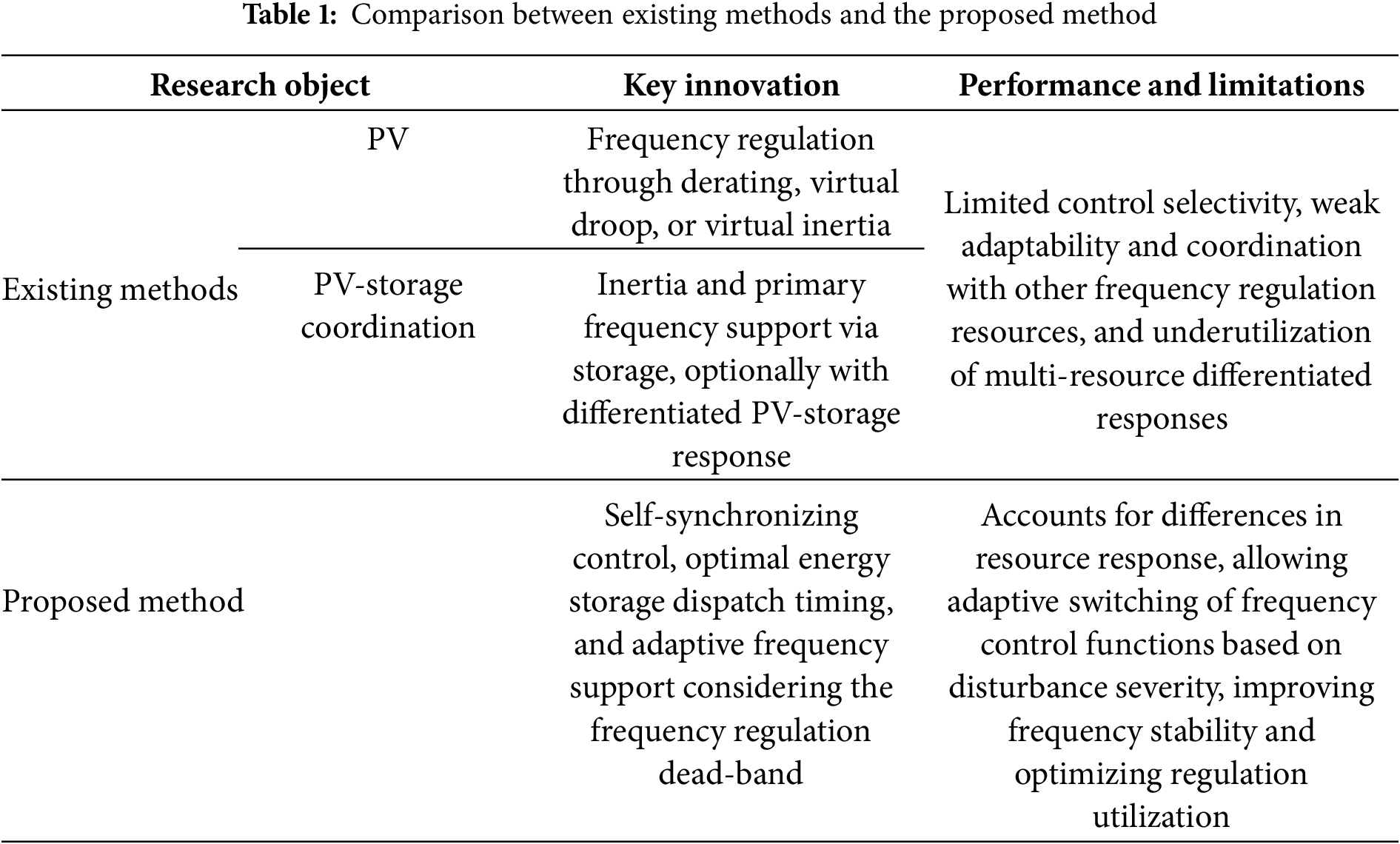
In summary, the existing control methods for PV systems participating in frequency regulation have not fully considered the coordinated support capability of multiple types of frequency regulation resources, and there is a problem of unreasonable utilization of frequency regulation resources. The specific comparison is shown in Table 1. Therefore, it is urgent to explore the regulatory potential of the PV-storage grid-connected system, clarify the response characteristic differences of multiple types of frequency regulation resources, make PV and energy storage present differentiated support characteristics under different disturbance conditions, and achieve reasonable utilization of frequency regulation resources while ensuring the safe and stable operation of the system frequency.
Under this background, this article aims to propose a multi-timescale frequency regulation coordinated control strategy for PV-storage integrated systems, which can ensure system frequency stability while fully leveraging the regulation capabilities of heterogeneous resources. The major novelty and contributions of this article are as follows:
• A inertia self-synchronization control strategy for grid-connected inverters is designed to enable active inertia support while transmitting frequency variation information, which can provide the response conditions for PV participation in frequency regulation without communication.
• A system frequency response model incorporating energy storage is established, and a method for determining the optimal activation time of energy storage in frequency regulation is proposed, which can effectively improve the frequency nadir.
• A active frequency support control strategy of PV considering frequency regulation dead zone is proposed. By appropriately designing the dead-band value, it enables effective coordination with synchronous generators and energy storage, allowing adaptive participation in frequency support according to disturbance severity, with the ability to switch between inertia support and primary frequency regulation.
2 Structure of PV-Storage Integrated System and Analysis of Its Frequency Support Requirements
2.1 Topological Structure of PV-Storage Integrated System
The topological structure of the PV-storage integrated system studied in this paper is shown in Fig. 1. In the figure, PPV is the output power of the photovoltaic array, and PSC is the output power of the supercapacitor. A positive value indicates that the supercapacitor is discharging, while a negative value indicates that the supercapacitor is charging. UPV is the port voltage of the photovoltaic; IPV is the output current of the photovoltaic; Udc is the DC bus voltage; Cdc is the capacitor on the DC bus side; USC is the port voltage of the supercapacitor; and ISC is the output current of the supercapacitor.
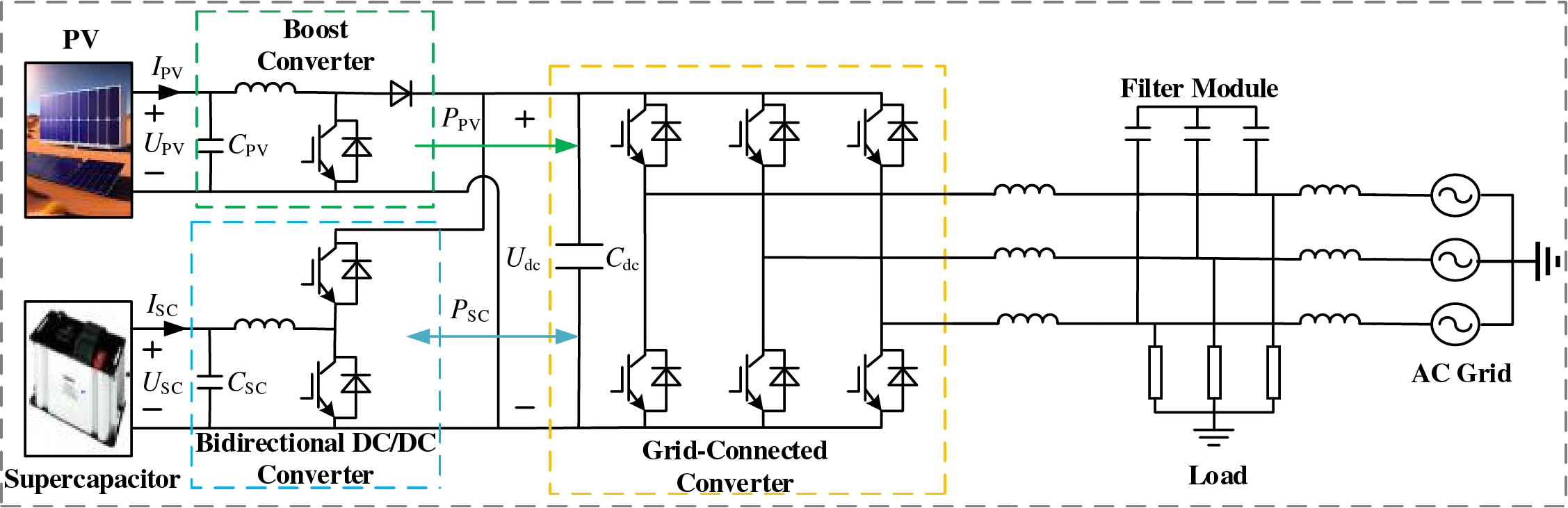
Figure 1: Structure of PV-storage integrated system
2.2 Analysis of Frequency Support Requirements
For the grid-connected system with high-penetration PV power generation, synchronous generators remain the main frequency regulation resources, showing significant differences from PV systems in terms of frequency regulation capability and response speed. Due to the intermittency and uncertainty of PV power generation, its frequency regulation capability also has the same characteristics, making it difficult to independently maintain the stable operation of system frequency. At present, it still plays the role of auxiliary frequency regulation. Therefore, under different disturbance conditions, the system’s frequency support requirements for PV will vary. In order to ensure the stability of system frequency and reduce the participation degree of PV systems, the power regulation margin of synchronous generators should be used as much as possible to bear the unbalanced power of the system, so as to reduce the scope of disturbance impact. According to the power regulation margin of synchronous generators and the unbalanced power in the PV-storage integrated system, the frequency support can be divided into the following three operating conditions.
Condition 1: After a load disturbance, when the disturbed power is small and the minimum frequency does not exceed the dead zone of the photovoltaic frequency control, the energy storage system and synchronous generator provide frequency support. If it exceeds the dead zone of the photovoltaic frequency control, the photovoltaic system and synchronous generator will provide frequency support.
Condition 2: After a load disturbance, if the constraint of Eq. (1) is satisfied, it means that the power regulation margin of the synchronous unit is sufficient to bear the system’s unbalanced power. Since frequency fluctuations caused by load disturbances are quite common during system operation, in most cases, the primary frequency regulation of the synchronous generator can maintain system frequency stability, so the probability of this scenario occurring is generally high. In this condition, the PV-storage integrated system and synchronous generator jointly regulate the system’s unbalanced power during the dynamic process. After returning to steady state, the unbalanced power is completely borne by the synchronous generator, and the photovoltaic system only provides inertia support
where ΔPmax is the power regulation margin of the synchronous unit; ΔPload is the unbalanced power of the system.
Condition 3: After a power disturbance, the system’s unbalanced power fails to meet the constraint of Eq. (1), indicating that the power regulation margin of the synchronous unit is insufficient to bear the unbalanced power. Since large-power disturbances in the system are usually caused by faults, their occurrence probability is lower compared to load disturbances. Therefore, to maintain the safety and stability of the system frequency, photovoltaics need to jointly participate in the primary frequency regulation of the system. Meanwhile, to reduce the impact of photovoltaic power generation during the system frequency regulation process, the synchronous unit should be responsible for the main frequency regulation task. On the basis of fully exerting its maximum frequency regulation capability, photovoltaics are then used to bear the remaining unbalanced power to maintain the system frequency stability. In this condition, when the system frequency reaches a steady state again after the disturbance, both photovoltaics and synchronous units bear the unbalanced power, and the photovoltaic system provides inertia while participating in primary frequency regulation.
3 Multi-Timescale Frequency Regulation Coordinated Control Strategy
A multi-time scale frequency regulation control strategy for coordinated cooperation of three frequency regulation resources is proposed in view of the frequency support requirements of the photovoltaic-storage grid-connected system under three working conditions, combined with the advantages of the fast response speed of the photovoltaic-storage system and the strong frequency regulation capability of the synchronous generator. The design principles of relevant control parameters are given to enable the photovoltaic-storage system to adaptively switch between inertia support and primary frequency regulation functions. While making full use of the frequency regulation capability of the synchronous generator, the influence range of disturbances is reduced, the rational use of frequency regulation resources is realized, and the frequency security and stability of the new energy power system are effectively improved.
3.1 Inertia Self-Synchronization Control
For the grid-connected inverter of the photovoltaic-storage system, an inertia self-synchronization control strategy based on the dynamic characteristics of DC capacitors is designed, and the specific control block diagram is shown in Fig. 2.
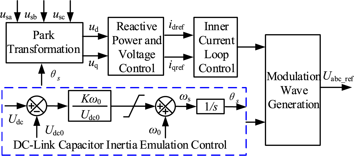
Figure 2: Inertia self-synchronization control of DC capacitor for PV-storage integrated system
In the figure, usa, usb, and usc are the three-phase AC voltages at the point of common coupling (PCC); ud and uq are the PCC voltages in the dq coordinate system; idref and iqref are the inner-loop current reference values; and Uabc_ref is the three-phase regulation voltage.
This control strategy exhibits the characteristics of a voltage source, enabling the inverter to achieve phase-locked loop (PLL)-free self-synchronization grid connection, thereby improving the frequency support capability under weak grid conditions. At this time, the DC voltage can follow the changes in the grid frequency like the rotor of a synchronous generator, transmitting the fluctuation information of the AC-side grid frequency. The control principle is as follows.
The rotor motion equation of a synchronous generator can be described as follows
where J represents the rotor moment of inertia; ωm is the angular frequency of the synchronous generator; Pm is the mechanical power; Pe is the electromagnetic power.
In the PV-storage system, the characteristic equation of the DC capacitor voltage on the high-voltage side changing with power is shown in Eq. (3), which can be used to describe the dynamic variation characteristics of the capacitor voltage caused by unbalanced power
where Pin represents the output power of the photovoltaic-storage system; Pout represents the output power of the grid-connected inverter.
By drawing an analogy between the synchronous generator rotor motion equation and Eq. (3), the following correspondences and insights can be derived
where Js represents the virtual moment of inertia of the grid-connected inverter; ωs is the output angular frequency of the grid-connected inverter.
It can be seen that the output angular frequency ωs and phase θs of the grid-connected inverter have a coupling relationship with the DC voltage Udc as shown in Eq. (5), and the relationship between Pout and θs is shown in Eq. (6).
where ω0 is the rated output angular frequency of the grid-connected inverter; K is the coupling coefficient between the DC voltage Udc and the inverter output frequency ωs; Udc0 is the steady-state DC voltage under normal operation; s is the integral operator; Es is the internal voltage of the grid-connected inverter; X is the equivalent reactance; U0 and θ0 are are the grid-connected point voltage and phase, respectively.
It can be seen from Eqs. (5) and (6) that the output angular frequency of the grid-connected converter can change with the variation of the capacitor voltage during power imbalance, thereby adjusting the output power of the grid-connected converter to endow it with response characteristics similar to those of a synchronous generator, which generates the grid-connected synchronous frequency and phase to achieve self-synchronization. Compared with conventional PLL-based synchronization, the proposed inertia self-synchronization control directly establishes the voltage phase without relying on external phase detection, thereby offering enhanced frequency and voltage regulation capabilities.
3.2 Energy Storage Frequency Regulation Control Strategy
The system frequency response model considering energy storage support power is shown in Fig. 3. In the figure, 1/R is the governor gain; TRH is the reheat component time constant; FHP is the power proportion coefficient of the high-pressure cylinder of the steam turbine; TG is the time constant of the synchronous generator governor; and s is the Laplace operator [21].
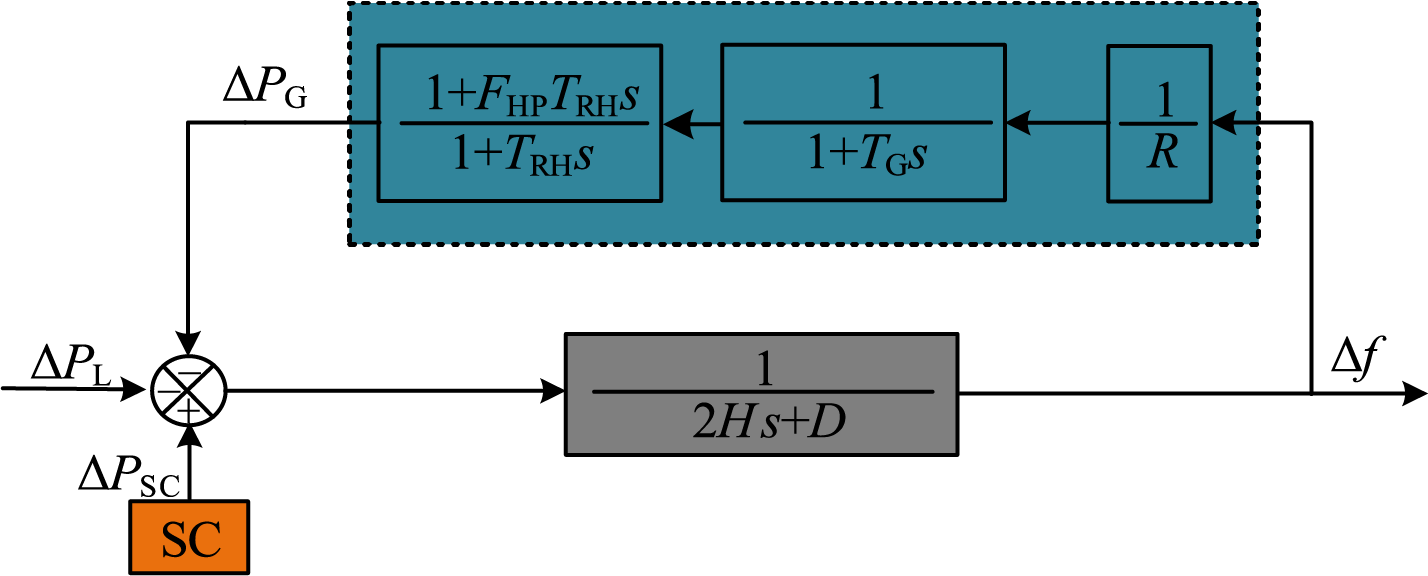
Figure 3: Frequency response model of systems containing energy storage
The closed-loop transfer function from load disturbance power to frequency is derived through Fig. 3, as shown in Eq. (7).
The system parameters are set as R = 5%, TG = 0.5 s, H = 6.5 s, D = 0, ΔPL = 0.05, PS = 0.05, FHP = 0.245, TRH = 10. Using the operational rules and methods of the inverse Laplace transform, the time-domain response of the system frequency under a step load change is determined by transforming the closed-loop transfer function from load to frequency in the complex frequency domain into a time-domain expression:
When PL increases by 5%, the frequency response of the system is shown in Fig. 4.
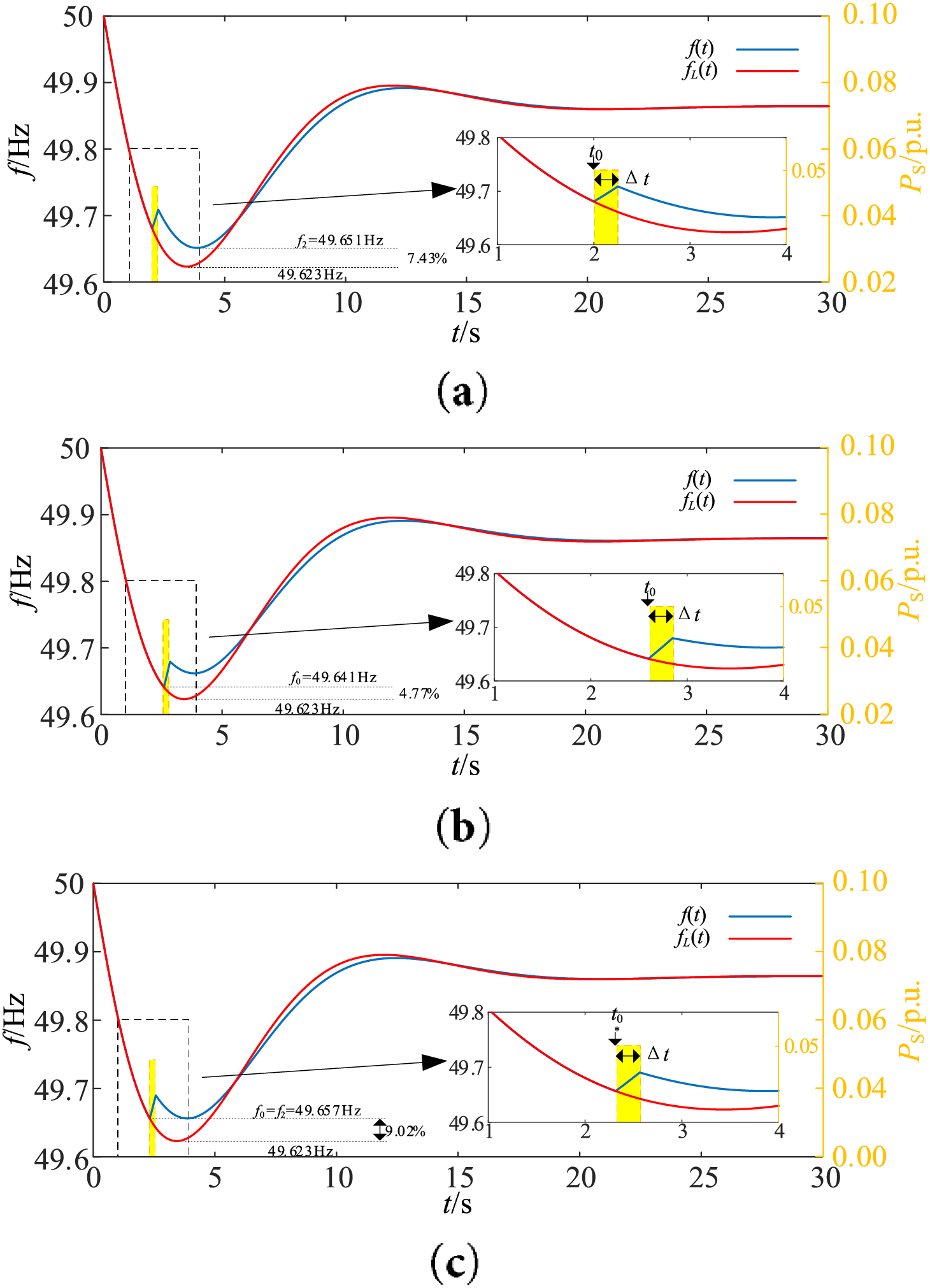
Figure 4: Frequency response of the system at increasing load. (a) When the energy storage power starts to support at t0 = 2 s; (b) When the energy storage power starts to support at t0 = 2.6 s; (c) When the energy storage power starts to support at t0 = 2.315 s
In Fig. 4, the blue and red lines represent the cases with and without energy storage power support, respectively; the power injected by the energy storage is denoted by the yellow dashed line. The time tn when the minimum frequency occurs can be obtained by setting the time derivative of fL(t) to zero dfL(t)/dt|t=tn = 0. After a power disturbance, the energy storage supports the system with power at a given time to raise the minimum frequency.
Therefore, the time t0 must be set before the occurrence of the minimum frequency (i.e., t0 < tn).
If the energy storage power is activated at t0 = 2 s and deactivated after 0.25 s (i.e., Δt = 250 ms), with the injected power PS = 5% (5% of the generator’s rated power). Fig. 4a shows the energy storage injected power and the resulting system frequency (yellow dashed line and blue line, respectively). The power injection mitigates the frequency drop after t = t0 but subsequently, at t = t2 the frequency f2 (where the new minimum frequency occurs) drops below the value f0 = f(t0). In this case, a 7.43% improvement in the minimum frequency is achieved.
On the other hand, as shown in Fig. 4b, if the power t0 = 2.6 s is injected at PS, the frequency at t = t0 is lower than that at t = t2. In this case, the improvement in the minimum frequency is 4.77%. It can be seen that injecting power at 2 s is too early, while starting at 2.6 s is too late. Therefore, theoretically, there should be an optimal power injection time to maximize the improvement of the minimum frequency, as shown in Fig. 4c.
It can be seen that by selecting the energy storage support time t0 such that the frequencies f0 and f2 are equal (i.e., t0 satisfies the condition f(t0) = f(t2)), the minimum frequency can be maximally improved. The optimal t0 for maximizing the minimum frequency improvement is denoted as t0* in this paper.
To determine the optimal time t0*, for energy storage support power, the time-domain expression of the system frequency response including the energy storage support power is calculated. The system frequency response can be decomposed into the combined effect of three disturbances: a step increase in PL at t = 0 s, a step increase in PS at t = t0, and a step decrease in PS at t = t1, where t1 = t0 + Δt. Therefore, the system frequency response f(t) can be represented as the following piecewise function:
wherein, substituting Eq. (8) into Eq. (9) allows solving for fL(t). The functions fs0 and fs1 are given by fs0(t) = fs(t − t0) and fs1(t) = fs(t − t1), respectively, where fs(t) is the time-domain response of the system frequency to a step change in PS. Similarly to the load step case, fs(t) can be obtained by applying the inverse Laplace transform:
Fig. 5 shows the piecewise function f(t) and the piecewise function defined in Eq. (9).
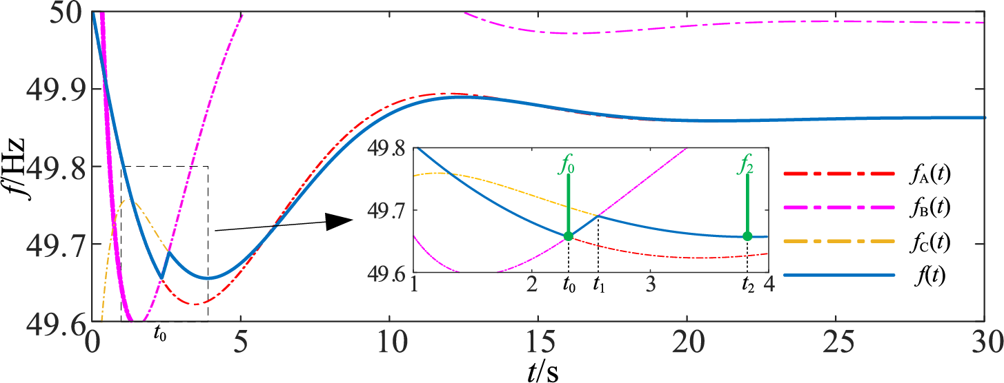
Figure 5: The segmented representation of the frequency response of the power PS provided by the energy storage between t0 and t1
The process for calculating the optimal activation time t0* of the support power can be summarized as follows. First, the value of f0 is calculated as f0 = fA(t0) using Eq. (9). Second, the time (expressed in terms of t0) is obtained by solving the equation dfC(t)/dt|t=t2 = 0. Then, the value of f2 is calculated as f2 = fC(t2). Where:
Finally, the optimal time t0* for power support is obtained from the equality condition.
It should be noted that in Eq. (12), both f0 and f2 are functions of the support power time t0. Different power system inertia and energy storage support power values will affect the minimum frequency and the optimal time t0* for support power. In the case shown in Fig. 4c, where H = 6.5 s and PS = 5%, the optimal time for support is t0* = 2.315 s.
When unbalanced power occurs in the system, the minimum frequency is calculated through the transfer function. If the minimum frequency is lower than the photovoltaic (PV) frequency regulation dead zone, the energy storage system control strategy is used to solve for the energy storage power support time, and power support is provided in a set power form to maximally raise the minimum frequency.
3.3 Frequency Support Control Strategy of PV Considering Frequency Regulation Dead Zone
To enable PV systems to provide primary frequency regulation under power disturbances, it is necessary to implement load-shedding strategies to reserve a certain amount of frequency regulation standby capacity. In other words, the PV system does not operate in maximum power point tracking (MPPT) mode, allowing it to offer active frequency support and rapid power reserves during grid disturbances, thereby enhancing overall system stability. Although it slightly reduces instantaneous power generation, this short-term loss can be compensated by participating in frequency regulation markets and providing ancillary services. On the basis of load-shedding standby capacity, the DC voltage deviation is introduced into the frequency control loop. Combined with the design of voltage deadband parameters, this enables PV systems to actively participate in grid frequency regulation.
The principle of the control strategy can be mathematically expressed by Eq. (13), as shown below.
where Δud is Voltage deadband value in the frequency control loop; Kp is proportional coefficient; Ki is integral gain; σ% is load-shedding coefficient (set to 20%); ΔPPV is regulation power during frequency support; P0 is initial power value after PV load-shedding; Ppv_ref is reference value of PV output power.
The control block diagram of the corresponding Boost converter is illustrated in Fig. 6. In the diagram, PWM denotes Pulse Width Modulation, PI represents the Proportional-Integral controller. Pi is the PV output regulation variable generated through the integral element. To prevent excessive PV power regulation, its amplitude limits are set to Pimin~0 and 0~Pimax, respectively; To constrain ΔPPV within the reserve capacity while avoiding excessive PV curtailment, its upper limit ΔPmax and lower limit ΔPmin are set to 0.2 and −0.2, respectively.
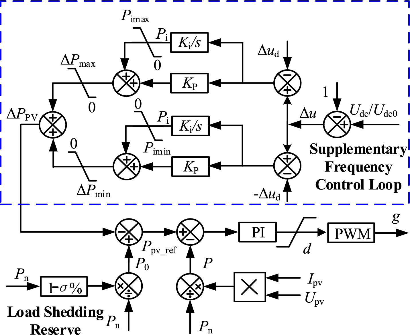
Figure 6: Frequency support control strategy of PV
Taking the frequency dip after a system disturbance as an example, the detailed working principle of the control strategy is described as follows.
When the load increases, the system frequency decreases, and the DC voltage decreases accordingly. After the DC voltage deviation exceeds the dead zone, the control link starts to act. The proportional controller and the integral controller start to adjust the power that the photovoltaic needs to support and change the power reference value.
The difference between the power reference value and the actual value passes through the PI controller to obtain the duty cycle d. Then, it drives the Boost circuit to work, changes the output voltage of the low-voltage side of the photovoltaic, further increases the photovoltaic output power, and suppresses the system frequency change. When the voltage deviation is smaller than the dead-zone value, the adjustment amount of the photovoltaic will gradually decrease until the control output is 0.
(1) Design of Coupling Coefficient K
To ensure that the DC voltage fluctuation of the PV-storage integrated system remains within a reasonable range during frequency stability support, the coupling coefficient K should be reasonably valued. Under normal circumstances, the system frequency change does not exceed ±1%, and the DC voltage change range is within ±5%. Substituting these into Eq. (5) yields Eq. (14). Through calculation, the minimum value of K is obtained as 0.2.
Considering that the frequency may temporarily exceed ±1% during the dynamic regulation process, according to the relevant provisions of the Technical Specifications for Photovoltaic Power Stations Connected to Power Systems, when the frequency is within the range of 48 to 49.5 Hz, the photovoltaic power station should have the capability to operate for at least 10 min. In practical applications, the frequency lower limit should be set according to the minimum allowable operating frequency of the photovoltaic power station inverter. In this paper, the frequency lower limit is set to 48.5 Hz, that is, the maximum value of K is 0.6 (0.03/0.05). To ensure that the DC voltage can be maintained within the safe range during the dynamic frequency regulation process, the value of K is taken as 0.6.
(2) DC Voltage Dead Zone Design
To fully leverage the frequency regulation advantages of PV and synchronous units, the dead zone value of the frequency support control strategy for the PV-storage integrated system is designed by utilizing the power regulation margin of the primary frequency regulation capability of synchronous units. This value ensures that when the frequency regulation capability of synchronous units is fully released, the PV-storage integrated system absorbs the excess unbalanced power. While fully utilizing the frequency regulation capability of synchronous generators, it reduces the unbalanced power that the PV system needs to absorb, as specifically shown in Eq. (15).
where Rp is the droop coefficient of the primary frequency regulation of the synchronous generator; ΔPmax is the per-unit value of the power regulation margin for the primary frequency regulation of the synchronous generator; Δfm is the per-unit value of the frequency deviation corresponding to the power regulation margin of the primary frequency regulation of the synchronous generator. According to the parameters of the synchronous generator used in this paper, the calculation shows that Δfm = 0.005.
According to the established coupling relationship between DC voltage and frequency, the relationship between the DC voltage dead zone value Δud and Δfm is shown in Eq. (16).
Based on the above analysis, it can be seen that Δud determines the unbalanced power borne by the photovoltaic power generation system and the dynamic response of the system frequency during the active frequency support process. It can effectively coordinate the frequency regulation power distribution between the synchronous generator and the PV system, ensuring the stability of the system frequency while reducing the degree of participation of the photovoltaic power generation system in frequency regulation, and avoiding the randomness of PV from affecting the stability of the power grid.
Take the frequency drop as an example to describe the action logic of the multi-agent frequency support coordination control strategy: When the load disturbance is less than or equal to the maximum power regulation margin of the synchronous generator, If the unbalanced power is small and does not reach the dead zone Δud, the synchronous generator acts, and the energy storage power support control is activated. After the system recovers stability, only the synchronous generator bears the unbalanced power. If the unbalanced power is large, the synchronous generator acts. When Δu exceeds the dead zone Δud, the energy storage power support control is locked, and the photovoltaic (PV) frequency support control is activated. When the system recovers to Δu < Δud, the PV frequency support control gradually withdraws and restores to nominal levels to prepare for resisting the next power disturbance. After the frequency reaches a new steady state, only the synchronous generator is responsible for bearing the unbalanced power, while the PV-storage system only provides inertia support.
When the load disturbance is greater than the maximum power regulation margin of the synchronous generator: After the unbalanced power is generated, the synchronous generator acts, and the energy storage inertia support control is activated. When Δu exceeds the dead zone Δud, the energy storage power support control is locked out, and the PV frequency support control is activated. When the frequency deviation reaches its peak, the energy storage starts charging. After the system reaches a new steady state, the synchronous generator and PV jointly bear the unbalanced power. The maximum power regulation margin of the synchronous generator is fully utilized, and the PV-storage system exhibits the functions of primary frequency regulation and inertia support.
The implementation process of multi-timescale frequency regulation coordinated control strategy is shown in Fig. 7, which can adaptively switch between inertia support and primary frequency regulation functions under different disturbance conditions, ensuring system frequency stability while fully utilizing the power regulation margin of synchronous generators.
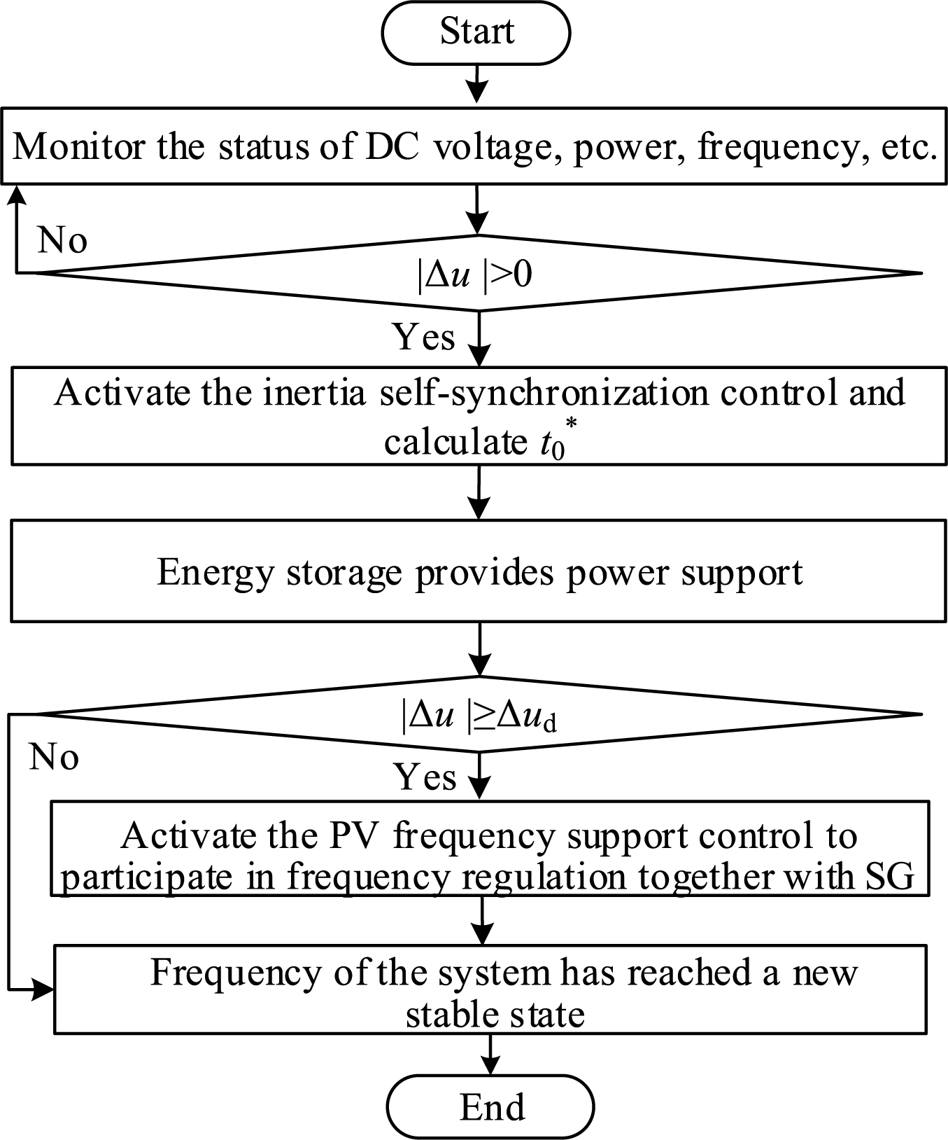
Figure 7: Implementation process of frequency regulation coordinated control strategy
A system simulation model of an actual power grid network topology as shown in Fig. 8 is built based on the RTLAB OP5707XG-8 real-time digital simulation platform, with a simulation step size of 50 μs. The photovoltaic power station connected to the QJ bus has a rated capacity of 300 MW and is equipped with a 1 MWh supercapacitor, while the synchronous generator unit connected to the BCR bus has a rated capacity of 900 MW. When the system operates stably, the PV output power at QJ is 240 MW (load reduction rate σ% = 20%), and the synchronous generator output power at BCR is 810 MW. It should be noted that the PV-storage systems at QJ adopts the control strategy proposed in this paper, while other wind power and PV systems do not participate in frequency events, and all set load disturbances are applied at QJ.
Figure 8: Simulation model based an actual power grid network topology
The main parameters of the simulation system are shown in Table 2. The photovoltaic cell model is SunPower SPR-305E-WHT-D.
To verify the frequency support capability of the control strategy proposed in this paper, three working cases are set up for validation: Case 1: At t = 40 s, the load increases by 30 MW, with no power support from energy storage; Case 2: At t = 40 s, the load increases by 70 MW, with energy storage supporting in the form of a square wave; Case 3: At t = 40 s, the load increases by 105 MW, with energy storage supporting in the form of a triangular wave with the same energy magnitude as the square wave.
For Case 2 and Case 3, simulation comparison and analysis are conducted for the following different control methods: Method 1: Without additional control, only synchronous generators participate in system frequency regulation; Method 2: Photovoltaic-storage additional frequency control, i.e., the proposed frequency support coordinated control strategy. Meanwhile, to verify the rationality of the dead-zone ud parameter design, simulation comparison and analysis of the proposed control strategy are carried out using voltage dead-zone values corresponding to frequency deviations of 0.20, 0.25, and 0.3 Hz, respectively.
4.1 Simulation Analysis of Case 1
The simulation results for Case 1 are shown in Fig. 9, and the analysis is as follows. When supporting with square-wave power, the lowest frequency point is improved to the greatest extent. However, this form of frequency support causes the frequency curve to be non-smooth, and a secondary drop occurs. When supporting with triangular-wave power, the frequency curve is smoother than that of the square-wave form, and the maximum value of the supporting power can be reduced. The trade-off is that the improvement degree of the lowest frequency point is slightly smaller than the former. Nevertheless, both forms effectively enhance the lowest frequency point.
Figure 9: Schematic diagram of simulation results for Case 1. (a) Grid frequency; (b) Energy storage support power
4.2 Simulation Analysis of Case 2
The simulation comparison results of the two methods for Case 2 are shown in Fig. 10, and a phased analysis is conducted to highlight the effectiveness and advantages of the control strategy proposed in this paper.
Figure 10: Schematic diagram of simulation results for Case 2. (a) System frequency; (b) DC voltage; (c) Output power of photovoltaic power station; (d) Output power of synchronous generator
As shown in Fig. 10a,b, the system frequency can be accurately and real-time transmitted to the PV-ES system via the DC voltage, verifying the effectiveness of the DC capacitor inertia synchronization control. Meanwhile, it also confirms the feasibility of using DC voltage information to enable the PV-ES system to participate in frequency support.
According to the simulation results, after the system load increases by 70 MW, the system frequency drops rapidly. Under the proposed coordinated control strategy for frequency support with multi-agent participation, the system frequency deviation reaches its peak at 44.32 s, that is, the frequency offset stage is from 40 to 44.32 s. It can be seen from Fig. 10a,c: When the voltage value exceeds the voltage dead-zone value of the control loop, the PV system starts to bear the unbalanced power. The frequency regulation capability of the PV system is fully utilized, which reduces the rate of frequency change, improves the minimum frequency point, reduces the overshoot, and effectively improves the system frequency, as shown in Table 3.
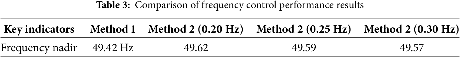
Compared with the proposed control under other dead-zone parameters: A smaller dead-zone value improves the minimum frequency point but fails to fully utilize the frequency regulation capability of synchronous generators. A larger dead-zone value fully utilizes the frequency regulation capability of synchronous generators, but leads to a larger peak frequency deviation. The coordinated control strategy for frequency support with multi-agent participation proposed in this paper shows better frequency support effects: it not only fully utilizes the frequency regulation capability of synchronous generators but also achieves a higher minimum frequency point. As shown in Fig. 10d, additional power output of synchronous generators in the early disturbance stage is lower than that in Method 1, indicating that the PV-storage integrated system quickly responds to the system unbalanced power under the action of frequency control and inertia control, relieving the frequency regulation pressure on traditional synchronous units.
The frequency rising stage after 44.32 s is the frequency recovery stage, and the coordinated frequency support control strategy of the PV-storage system and synchronous generators withdraws at 63.26 s. As shown in Fig. 10c: When the PV output continues to increase, the frequency deviation had reached its peak. After the PV output reaches the maximum value, the frequency has entered the recovery stage, where synchronous generators and PV jointly respond to the system unbalanced power. As the frequency recovers, once the frequency returns within the dead-zone value, the PV withdraws from frequency regulation and reverts to its initial operating state. The system frequency continues to recover under the action of the synchronous generator governor. After the system frequency stabilizes, the synchronous units assume all unbalanced power.
4.3 Simulation Analysis of Case 3
The simulation comparison results of the two methods for Case 3 are shown in Fig. 11. As can be seen from Fig. 11a,e: When only synchronous generators participate in frequency regulation, and the system unbalanced power exceeds the power regulation margin of synchronous units, the output power of synchronous units reaches the regulation upper limit. At this point, if the PV-storage system does not participate in regulation, the system frequency will continue to drop, leading to system frequency instability.
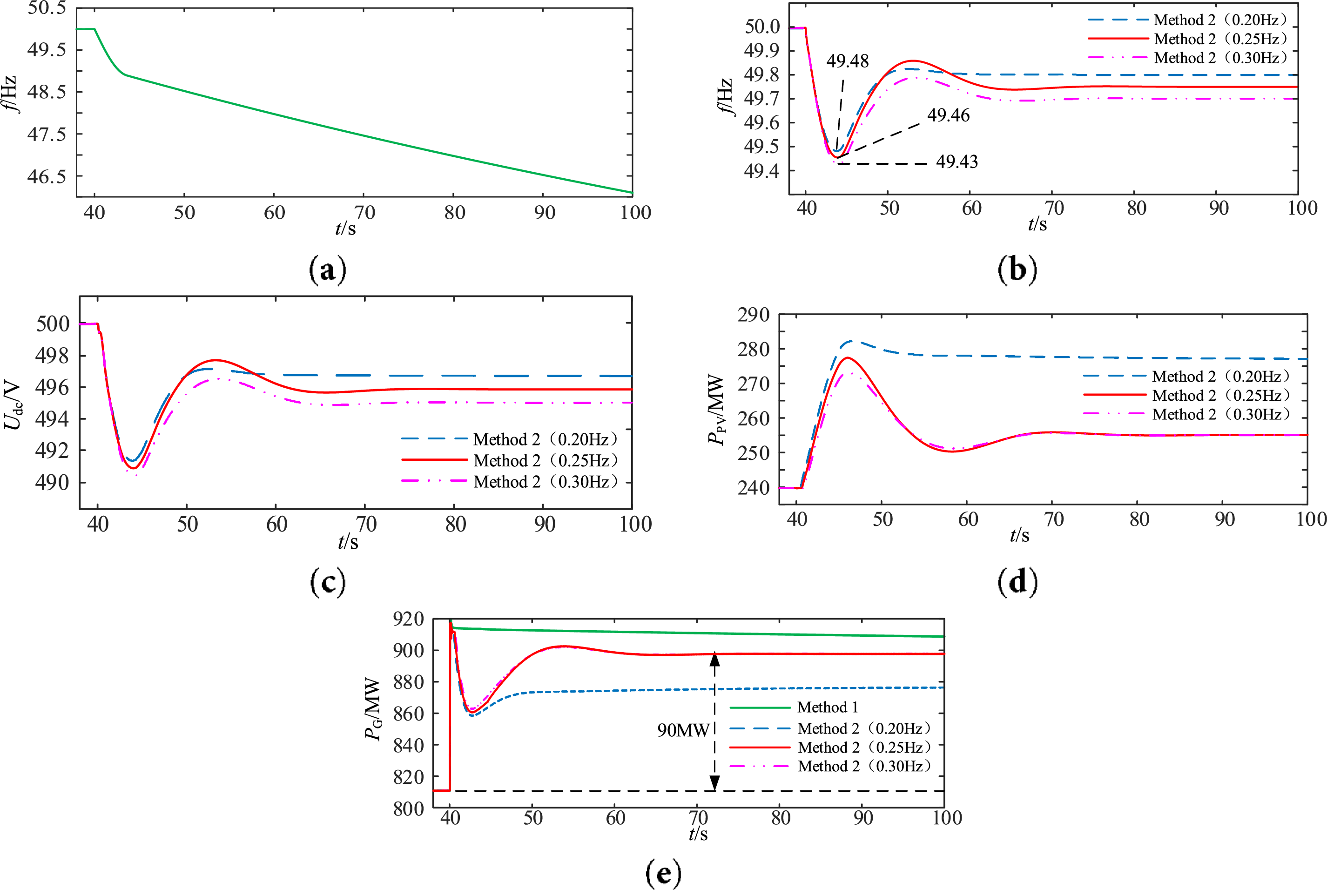
Figure 11: Schematic diagram of simulation results for Case3. (a) System frequency without additional control; (b) System frequency with additional control; (c) DC voltage; (d) Output power of PV; (e) Output power of synchronous generator
Under the frequency support control proposed in this paper, the system frequency deviation reaches its peak at 44.05 s for the PV-ES system, meaning the frequency offset stage is from 40 to 44.05 s. The role of PV in this stage is consistent with that of Stage 1 in Case 1, and the phenomena exhibited by using larger or smaller dead-zone values are the same as those in Case 1, so they will not be repeated here.
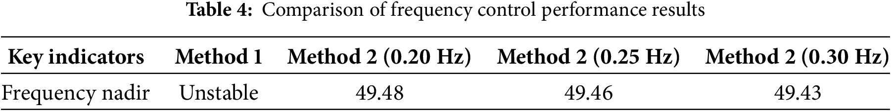
The frequency rising stage after 44.05 s is the recovery stage. As shown in Fig. 11b–e: Due to the limited power regulation margin of synchronous units, and the dead-zone value Δud of the control loop is designed based on the power regulation margin of synchronous generators, when the output power of synchronous generators is limited, the remaining unbalanced power is borne by the PV system. The synchronous units finally assume 90 MW of unbalanced power, fully utilizing the primary frequency regulation capability of synchronous generators, while the PV assumes 15 MW of unbalanced power. The two jointly maintain the system frequency stability. At this time, the PV plays the role of primary frequency regulation to adjust the system frequency. When the system recovers stability, the frequency deviation stabilizes within the dead-zone value. The comparison results of frequency control performance are shown in Table 4.
Aiming at the frequency stability issues caused by low inertia and weak damping of the system, this paper proposes a coordinated control strategy for frequency support applicable to PV-storage integrated system and its parameter design principles. The strategy enables adaptive switching between inertia support and primary frequency regulation, realizes rational utilization of multiple frequency regulation resources, improves the minimum frequency point under different working conditions, and effectively enhances the safety and stability of the frequency in PV-storage integrated systems. The simulation analysis leads to the following conclusions:
(1) For the working condition where the synchronous generator can completely absorb the unbalanced power, the inertia self-synchronization control of the grid-connected inverter provides response conditions for the PV-storage system to actively support the system frequency. Through dynamic adjustment of the DC-side capacitor, energy storage, and PV output, the rate of frequency change and frequency deviation are effectively reduced. In this condition, the PV-storage system only exhibits the role of inertia support.
(2) For the working conditions where the synchronous generator cannot completely absorb the unbalanced power, the rational design of the frequency regulation dead-zone value can fully utilize the maximum frequency regulation capability of the synchronous generator. In this case, the PV-storage system not only provides inertia support but also undertakes the primary frequency regulation task. During steady state, the frequency deviation is stabilized within the dead-zone value, and the energy storage adaptively recovers to the initial operating state, realizing the rational utilization of frequency regulation capability while maintaining the system frequency stability.
Acknowledgement: The authors thank the Northeast Electric Power University for conducting this research.
Funding Statement: This study is supported by the State Grid Corporation of China under Grant for Science and Technology Projects (No. SGNXJYOOZWJS2500029).
Author Contributions: The authors confirm contribution to the paper as follows: Junxian Ma: Funding acquisition, study design. Haonan Zhao: Validation, original draft. Zhibing Hu: Project administration, data analysis. Yaru Shen: Supervision. Fan Ding: Software. Shouqi Jiang: Methodology. All authors reviewed the results and approved the final version of the manuscript.
Availability of Data and Materials: Data will be made available on request.
Ethics Approval: Not applicable.
Conflicts of Interest: The authors declare no conflicts of interest to report regarding the present study.
References
1. Wang Z, Ni F. Maximum power point tracking based on improved Kepler optimization algorithm and optimized perturb & observe under partial shading conditions. Energy Eng. 2024;121(12):3779–99. doi:10.32604/ee.2024.055535. [Google Scholar] [CrossRef]
2. Yang DQ, Li MJ, Ma T, Ni JW, Han ZY. Study on adaptive VSG parameters and SOC control strategy for PV-HESS primary frequency regulation. Energy. 2025;314(3):133909. doi:10.1016/j.energy.2024.133909. [Google Scholar] [CrossRef]
3. Li YL, Zhao F, Fan XJ. Review of grid-forming energy storage and its applications. Power Gener Technol. 2025;46(2):386–98. doi:10.12096/j.2096-4528.pgt.24052. [Google Scholar] [CrossRef]
4. Jiang MH, Li D, Kong DZ, Wang Z, Bai NN, Li ZW. Multi-source coordinated control and parameter optimization methods for frequency stability in high-proportion new energy sending-end systems. Electr Power Constr. 2025;46(5):36–46. doi:10.12204/j.issn.1000-7229.2025.05.004. [Google Scholar] [CrossRef]
5. Ramesh M, Yadav AK, Pathak PK. An extensive review on load frequency control of solar-wind based hybrid renewable energy systems. Energy Sources Part A Recovery Util Environ Eff. 2025;47(1):8378–402. doi:10.1080/15567036.2021.1931564. [Google Scholar] [CrossRef]
6. Zhang R, Ren X, Liu Z, Bie Z, Chen C. Distributed cooperative secondary frequency control for power system penetrated with renewable energy sources and energy storage with communication time delays. Int J Electr Power Energy Syst. 2025;164(8):110411. doi:10.1016/j.ijepes.2024.110411. [Google Scholar] [CrossRef]
7. Zhang J, Sun P, Dong G, Chen Y. Adaptive power regulation-based coordinated frequency regulation method for PV and energy storage system. J Energy Storage. 2025;106(1):114794. doi:10.1016/j.est.2024.114794. [Google Scholar] [CrossRef]
8. Ray I, Tolbert LM. Grid-forming inverter control design for PV sources considering DC-link dynamics. IET Renew Power Gener. 2025;19(1):e12454. doi:10.1049/rpg2.12454. [Google Scholar] [CrossRef]
9. Rahmann C, Castillo A. Fast frequency response capability of photovoltaic power plants: the necessity of new grid requirements and definitions. Energies. 2014;7(10):6306–22. doi:10.3390/en7106306. [Google Scholar] [CrossRef]
10. Kakimoto N, Takayama S, Satoh H, Nakamura K. Power modulation of photovoltaic generator for frequency control of power system. IEEE Trans Energy Convers. 2009;24(4):943–9. doi:10.1109/TEC.2009.2026616. [Google Scholar] [CrossRef]
11. Xin H, Liu Y, Wang Z, Gan D, Yang T. A new frequency regulation strategy for photovoltaic systems without energy storage. IEEE Trans Sustain Energy. 2013;4(4):985–93. doi:10.1109/TSTE.2013.2261567. [Google Scholar] [CrossRef]
12. Nanou SI, Papakonstantinou AG, Papathanassiou SA. A generic model of two-stage grid-connected PV systems with primary frequency response and inertia emulation. Electr Power Syst Res. 2015;127:186–96. doi:10.1016/j.epsr.2015.06.011. [Google Scholar] [CrossRef]
13. Zhong C, Zhou Y, Yan G. A novel frequency regulation strategy for a PV system based on the curtailment power-current curve tracking algorithm. IEEE Access. 2020;8:77701–15. doi:10.1109/ACCESS.2020.2989785. [Google Scholar] [CrossRef]
14. Mao M, Tang Y, Chen J, Ma F, Li Z, Ma H, et al. An overview of solar photovoltaic power smoothing control strategies based on energy storage technology. Energies. 2025;18(4):909. doi:10.3390/en18040909. [Google Scholar] [CrossRef]
15. Baral KK, Nayak PC, Mohanty B, Barisal AK. Improved frequency regulation of dual-area hybrid power system with the influence of energy storage devices. Electr Eng. 2025;107(3):3511–32. doi:10.1007/s00202-024-02670-8. [Google Scholar] [CrossRef]
16. Alipoor J, Miura Y, Ise T. Power system stabilization using virtual synchronous generator with alternating moment of inertia. IEEE J Emerg Sel Top Power Electron. 2015;3(2):451–8. doi:10.1109/JESTPE.2014.2362530. [Google Scholar] [CrossRef]
17. Hernández JC, Bueno PG, Sanchez-Sutil F. Enhanced utility-scale photovoltaic units with frequency support functions and dynamic grid support for transmission systems. IET Renew Power Gener. 2017;11(3):361–72. doi:10.1049/iet-rpg.2016.0714. [Google Scholar] [CrossRef]
18. Hou Y, Liu J, Li X, Liu J. Energy storage minimization control in grid-connected photovoltaic virtual synchronous generator. In: Proceedings of the 2022 IEEE Energy Conversion Congress and Exposition (ECCE); 2022 Oct 9–13; Detroit, MI, USA. p. 1–6. doi:10.1109/ECCE50734.2022.9947765. [Google Scholar] [CrossRef]
19. Wang X, Yue M, Muljadi E. PV generation enhancement with a virtual inertia emulator to provide inertial response to the grid. In: 2014 IEEE Energy Conversion Congress and Exposition (ECCE); 2014 Sep 14–18; Pittsburgh, PA, USA. p. 17–23. doi:10.1109/ECCE.2014.6953370. [Google Scholar] [CrossRef]
20. Jia J, Yan X, Li T, Wang Y, Ma H. Fast frequency regulation strategy of PV power system assisted by energy storage based on improved measurement method of RoCoF. Trans China Electrotech Soc. 2022;37(S1):93–105. [Google Scholar]
21. Shi Q, Li F, Cui H. Analytical method to aggregate multi-machine SFR model with applications in power system dynamic studies. IEEE Trans Power Syst. 2018;33(6):6355–67. doi:10.1109/TPWRS.2018.2824823. [Google Scholar] [CrossRef]
Cite This Article
 Copyright © 2026 The Author(s). Published by Tech Science Press.
This work is licensed under a Creative Commons Attribution 4.0 International License , which permits unrestricted use, distribution, and reproduction in any medium, provided the original work is properly cited.
 Downloads
 Citation Tools