
 Submit a Paper
 Propose a Special lssue
 Open Access
ARTICLE

Multi-Dimensional Collaborative Optimization Strategy for Control Parameters of Thermal-Energy Storage Integrated Systems Considering Frequency Regulation Losses
Key Laboratory of Modern Power System Simulation and Control & Renewable Energy Technology, Northeast Electric Power University, Ministry of Education, Jilin, 132012, China
* Corresponding Author: Xingxu Zhu. Email:
Energy Engineering 2026, 123(3), 17 https://doi.org/10.32604/ee.2025.072679
Received 01 September 2025; Accepted 20 October 2025; Issue published 27 February 2026
 View Full Text
 Download PDF
Abstract
With the increasing penetration of renewable energy, the coordination of energy storage with thermal power for frequency regulation has become an effective means to enhance grid frequency security. Addressing the challenge of improving the frequency regulation performance of a thermal-storage primary frequency regulation system while reducing its associated losses, this paper proposes a multi-dimensional cooperative optimization strategy for the control parameters of a combined thermal-storage system, considering regulation losses. First, the frequency regulation losses of various components within the thermal power unit are quantified, and a calculation method for energy storage regulation loss is proposed, based on Depth of Discharge (DOD) and C-rate. Second, a thermal-storage cooperative control method based on series compensation is developed to improve the system’s frequency regulation performance. Third, targeting system regulation loss cost and regulation output, and considering constraints on output overshoot and system parameters, an improved Particle Swarm Optimization (PSO) algorithm is employed to tune the parameters of the low-pass filter and the series compensator, thereby reducing regulation losses while enhancing performance. Finally, simulation results demonstrate that the total loss cost of the proposed control strategy is comparable to that of a system with only thermal power participation. However, the thermal power loss cost is reduced by 42.16% compared to the thermal-only case, while simultaneously improving system frequency stability. Thus, the proposed strategy effectively balances system frequency stability and economic efficiency.Keywords
In response to the call for green and low-carbon development, China has in recent years vigorously promoted the optimization of its energy structure, resulting in continuous growth in the installed capacity of renewable energy sources such as wind and solar power [1]. However, the increasing penetration of renewable energy introduces significant challenges to power system frequency stability due to its intermittent and volatile nature, making it more difficult for conventional thermal power units to fulfill frequency regulation demands [2,3]. In comparison, battery energy storage systems (BESS) offer advantages including fast response, accurate control, and flexible power capacity. Thus, the collaboration between energy storage and thermal power in frequency regulation can effectively improve regulation performance and enhance generator operational efficiency [4–6].
Although the participation of energy storage alongside thermal power in grid frequency regulation improves system performance while reducing wear on thermal power units themselves, the large-scale integration of renewable energy forces thermal units to frequently and rapidly adjust their output to compensate for load and renewable generation fluctuations. This results in severe equipment wear and shortens the operational lifespan of the units [7]. Moreover, the current high capital costs of energy storage power plants, coupled with the generally short lifecycle of battery storage systems, mean that frequent charging and discharging also contribute to capacity degradation [8,9]. Therefore, analyzing the causes of equipment wear and operational losses in thermal power units, as well as the lifetime degradation of energy storage systems during frequency regulation, is of great significance for extending equipment service life and enhancing overall system economic efficiency.
Currently, battery energy storage systems assisting thermal power plants in grid frequency regulation have achieved notable progress and demonstrated promising results. Reference [10] introduced a variable universe fuzzy adaptive PI control strategy that utilizes frequency deviation as the input scaling factor. This approach effectively reduced system frequency deviation. Building on this, Reference [11] combined a trend control strategy with inertia and droop control, which significantly improved system frequency response and slowed the rate of grid frequency deterioration. Reference [12] proposes a configuration methodology for an Energy Storage System based on third-order Virtual Synchronous Generator control, aimed at the simultaneous enhancement of grid inertia response and primary frequency control. While the studies above enhanced energy storage utilization and improved grid frequency performance primarily through virtual droop or virtual inertia control strategies, they did not adequately account for the operational degradation and lifetime losses incurred by both the energy storage system and the thermal power plant during the frequency regulation process.
To address the trade-off between performance and cost, research efforts have been undertaken to mitigate frequency regulation losses in integrated thermal-energy storage systems. Reference [13] presents a hierarchical coordinated control strategy, including three layers: the system layer, the ESS operation layer, and the coordination control layer, which enhances system frequency regulation performance while reducing the lifespan degradation of the energy storage system. Reference [14] proposes an analytical formulation for the optimal operation of BESS in frequency regulation service, which strikes a balance between the revenue and the battery lifetime, which reduces the operational lifespan degradation of the battery. Reference [15] proposes multi-constrained optimal control strategy of energy storage combined thermal power participating in frequency regulation based on life model of energy storage, which reduces the cost associated with frequency regulation losses and extends the service life of the energy storage system, while maintaining regulation performance. References [16,17] took into account the differences in frequency regulation characteristics between thermal power and energy storage systems. They applied a low-pass filter to the combined primary and secondary frequency regulation commands, allocating the high-frequency components to the energy storage system and the low-frequency components to the thermal power unit. This strategy fully leverages the respective advantages of each regulation resource.
In addition to the coordinated strategies utilizing energy storage and thermal power, the academic field has witnessed the emergence of numerous advanced controller design and optimization methods for broader frequency control applications. Reference [18] integrated an Imperialist Competitive Algorithm optimized dual-mode controller with Capacitive Energy Storage and a Static Synchronous Series Compensator, demonstrating significant advantages in key performance indicators such as frequency deviation, tie-line power oscillations, and settling time. Furthermore, Reference [19] addressed Load Frequency Control in multi-microgrid systems with a high penetration of renewable energy by proposing an ICA-optimized controller incorporating an Integral-Tilt-Derivative Filter. This controller exhibited exceptional robustness against substantial variations in system parameters and diverse disturbances from both load and renewable sources.
Most of the aforementioned literature lacks a detailed analysis of the frequency regulation losses incurred by integrated thermal-energy storage systems during operation. While some studies propose simplified calculation methods for these losses, they remain inadequate for accurately assessing the total cost of frequency regulation. Furthermore, several approaches employ low-pass filters to decompose the regulation signal. However, analysis from the system’s overall magnitude-frequency characteristic perspective reveals that such filtering strategies can result in lower gain within the low-frequency region compared to systems relying solely on thermal power, potentially leading to suboptimal frequency regulation performance. Additionally, a significant shortcoming is the frequent neglect of practical constraints, such as preventing energy storage from over-charging or over-discharging, which can leave it unable to respond to allocated power commands.
Therefore, to clearly evaluate the frequency regulation losses of the thermal-storage system during the regulation process and to address the issues of insufficient regulation performance in traditional strategies and the poor trade-off between performance and loss, this paper proposes a multi-dimensional cooperative optimization strategy for the control parameters of a combined thermal-storage system that accounts for regulation losses.
Based on this analysis, the novel contributions of this work are as follows:
(1) Established a comprehensive quantitative model for regulation loss: A refined calculation method for the frequency regulation loss of various components in thermal power units was proposed. Furthermore, a novel energy storage loss model coupling Depth of Discharge (DOD) and C-rate was constructed. This model, based on irregular cycle decomposition technology, enables a more accurate assessment of energy storage lifespan degradation.
(2) Designed a series compensation-based cooperative control strategy for the thermal-storage system: Building upon the traditional low-pass filter-based frequency division control, a series compensation module was introduced. This strategy not only effectively enhances the overall frequency regulation performance of the system but also addresses the practical issue where the energy storage system cannot respond to commands due to its operational limits, through a dynamic constraint mechanism.
(3) Constructed a constrained multi-objective optimization framework and parameter tuning method: Considering system output overshoot and parameter boundary constraints, a multi-dimensional optimization problem was established with the competing objectives of minimizing regulation loss cost and optimizing regulation output. An improved Particle Swarm Optimization algorithm was adopted to cooperatively optimize the filter and compensation parameters, thereby significantly improving frequency performance while simultaneously enhancing the system’s economy.
2 Primary Frequency Regulation Modeling of Thermal-Energy Storage Integrated Systems Considering Frequency Regulation Losses
2.1 Dynamic Model of the Thermal-Energy Storage Primary Frequency Regulation System
2.1.1 Frequency Regulation Model of Thermal Power Units
The thermal power unit is modeled considering three key components: the electro-hydraulic servo system, the oil servo system, and the steam turbine, as illustrated in the thermal power unit section of Fig. 1. Here, Gehs(s) denotes the transfer function of the electro-hydraulic servo system, Goil(s) represents the transfer function of the oil servo system, and Gst(s) corresponds to the transfer function of the steam turbine. ΔPref signifies the total frequency regulation output command for both the thermal and energy storage systems, while ΔPsum indicates their actual output. Δ
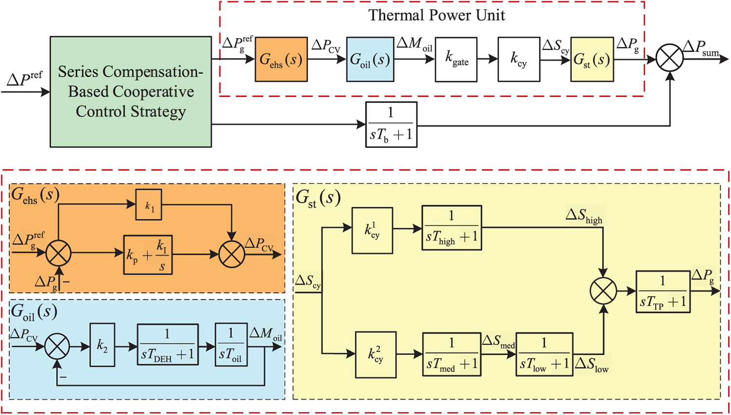
Figure 1: Thermal-storage coordinated control block diagram for primary frequency regulation
Given that the valve stem drives the steam intake of the cylinder, the total steam intake volume, along with the high-pressure cylinder steam volume ΔShigh, intermediate-pressure cylinder steam volume ΔSmed, and low-pressure cylinder steam volume ΔSlow, are given by Eqs. (1)–(4):
where, kcy denotes the positive proportionality factor between the steam admission valve stem displacement and the steam volume within the cylinder, while kgate represents the positive proportionality factor between the oil servomotor piston displacement and the valve stem opening. Thigh, Tmed, and Tlow are the time constants of the high-pressure, intermediate-pressure, and low-pressure cylinders, respectively, with the constraint that
The transfer function of the turbine output is thus given by Eq. (5):
where, TTP denotes the turbine rotor time constant.
The transfer function of the oil servomotor output is given by Eq. (6):
where, TDEH is the electro-hydraulic conversion time constant, Toil is the oil servomotor time constant, and k2 represents the proportional gain of the electro-hydraulic converter.
The transfer function of the electro-hydraulic control system output is given by Eq. (7):
where, k1 is the load control feedforward coefficient, kp is the proportional gain of the PID controller, kI is the integral gain of the PID controller, and GTP(s) denotes the overall transfer function of the thermal power unit.
Thus, the output transfer function of the thermal power unit can be given by Eq. (8):
During primary frequency regulation, when a system frequency deviation occurs, the relationship between the total output command for the thermal-energy storage system and the frequency deviation can be given by Eq. (9):
where, KG represents the speed droop coefficient of the thermal power unit.
2.1.2 Energy Storage Frequency Regulation Model
Battery energy storage systems exhibit rapid response and high precision in frequency regulation. To fully leverage these advantages in frequency regulation scenarios, they are commonly represented using a first-order inertial transfer function, denoted as Gb(s), which can be given by Eq. (10):
where, Tb is the time constant of the battery energy storage system.
Furthermore, to facilitate the calculation of battery lifespan degradation, the state of charge (SOC) is introduced, defined as the ratio of the remaining energy capacity to the rated capacity. The expression for SOC is given by Eq. (11):
where, Δt represents the sampling time interval, Sn is the rated capacity of the energy storage system, Pch(t) and Pdis(t) denote the charging and discharging power at time t, respectively, SOC(t) represents the state of charge at time t, and ηc, ηd are the charging and discharging efficiencies, respectively.
2.2 Calculation Method for Frequency Regulation Losses in the Thermal-Energy Storage Primary Frequency Regulation System
Based on the dynamic model of the thermal-energy storage primary frequency regulation system presented in Section 2.1, this section introduces the corresponding method for calculating frequency regulation losses. The calculation of frequency regulation losses in the integrated system primarily includes the losses of the thermal power unit—covering the oil servomotor, steam valve stem, rotor, and cylinder—as well as the energy storage losses evaluated based on DOD and C-rate.
2.2.1 Calculation Method for Frequency Regulation Losses in the Thermal Power Unit
(1) Frequency Regulation Losses of the Oil Servomotor
The oil servomotor is the component with the highest energy consumption within the digital electro-hydraulic (DEH) control system. Based on the aforementioned modeling of the thermal power unit, the piston displacement of the oil servomotor at time t during frequency regulation, denoted as ΔMoil,t, is calculated from the input command to the oil servomotor ΔSTP (i.e., the output signal after amplification by the proportional gain of the electro-hydraulic converter within the oil servomotor module) and is given by Eq. (12):
According to Archard’s wear theory, the wear volume Voil,t of the inner cylinder wall caused by piston sliding at time t is given by Eq. (13):
where, F is the friction coefficient, representing the volumetric wear per unit sliding distance of the piston against the inner cylinder wall, NF is the normal friction force, and MH is the material hardness.
The loss associated with the oil servomotor is then defined as the ratio of the increase in inner cylinder wall wear volume to a predetermined threshold, which can be given by Eq. (14):
where, Loil,t is the oil servomotor loss at time t, Y* is the threshold for the increase in inner wall radius (commonly set to 1.4 mm in practical engineering applications), Yoil,t is the increase in inner wall radius at time t, r is the piston radius, and d is the sliding distance of the piston along the cylinder wall.
(2) Frequency Regulation Losses of the Steam Valve Stem
The oil servomotor drives the movement of the steam admission valve stem, which regulates the steam flow. The greater the deviation of the piston from its central position, the larger the valve opening. The displacement of the valve stem is positively correlated with that of the piston. Thus, the stress on the steam valve stem at time t, denoted Δ
where, E is the modulus of elasticity, E* is the rated elastic modulus, and
The loss of the steam valve stem at time t, Lgate,t is given by Eq. (16):
where,
The frequency regulation losses associated with the turbine rotor and cylinder of the thermal power unit are provided in Appendix A and Appendix B, respectively.
2.2.2 Calculation Method for Frequency Regulation Losses in Energy Storage Systems
To establish a lifecycle degradation model for battery energy storage, this paper comprehensively considers the influence of both DOD and C-rate on battery aging. Battery aging is quantified by integrating the cycle life loss under charge-discharge cycles at different DOD levels with an aging factor that captures the impact of C-rate on degradation.
Based on battery cycle failure characteristics, DOD is recognized as the most critical factor affecting battery aging. Higher DOD leads to accelerated battery life consumption, which increases exponentially. Prior studies have demonstrated the effectiveness and accuracy of using exponential functions to model the relationship between cycle life and DOD. In this paper, the cycle life Ldod at a specific DOD is quantified using the following exponential function, as given by Eq. (17):
where,
The percentage loss per full cycle at this depth of discharge, denoted as dpcycle, can thus be given by Eq. (18):
In practical operation, battery energy storage systems often undergo partial rather than full cycles. It is therefore necessary to decompose such incomplete charge-discharge processes into equivalent full cycles. Any arbitrary charging or discharging process can be described as a transition of the battery’s depth of discharge from x% to y%. Assuming a specific relationship
Furthermore, any complete cycle from x% to y% and back to x% can be decomposed into the difference between two full cycles, as illustrated in Fig. 2. Consequently, the absolute difference in battery capacity fade percentage between these two full cycles corresponds to the capacity degradation percentage attributable to one complete cycle from x% to y% and back to x%, as given by Eq. (21):
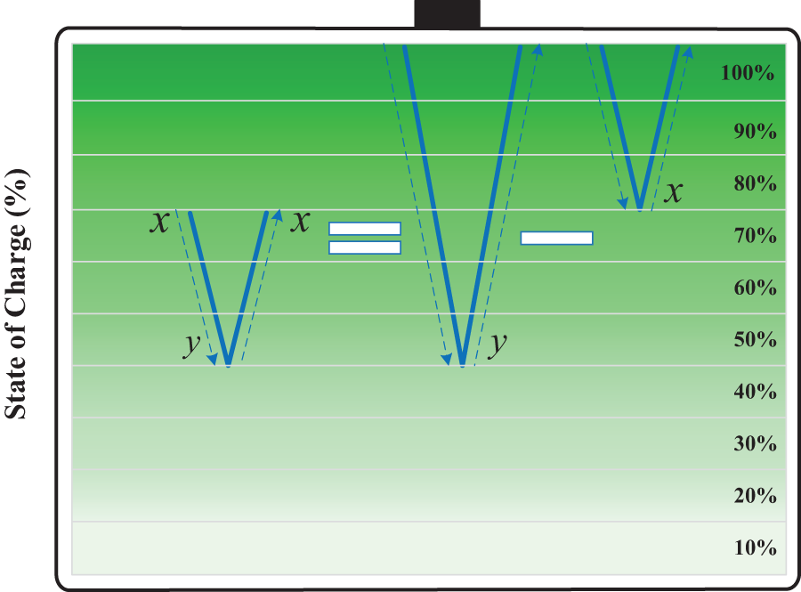
Figure 2: Schematic of irregular cycle decomposition
Therefore, the percentage of capacity fade resulting from a discharge from x% to y% is given by Eq. (22):
Combining the above equations, the percentage capacity loss per charge-discharge cycle from x% to y% can be expressed as Eq. (23):
In modeling energy storage systems, the SOC is typically used instead of DOD for computational convenience. Using the relation SOC = 1 − DOD, the percentage capacity loss per charge-discharge cycle from x% to y% is given by Eq. (24):
Battery discharge cycles at different C-rate levels have distinct impacts on battery lifespan. Previous studies have validated that polynomial functions can effectively capture the nonlinear relationship between C-rate and battery degradation. In this paper, to better model the effect of cycles under varying C-rate conditions, a C-rate scaling factor is introduced to adjust the capacity loss, as given by Eq. (25):
where, δcrate is an aging factor that reflects the influence of C-rate on battery degradation. It is a dimensionless coefficient whose value indicates the effect of C-rate variation on the aging rate; m1, m2, m3, and m4 are parameters derived from experimental data [22].
Here, Crate is calculated based on the operating power and the rated power of the energy storage system, as given by Eq. (26):
where, Pnom is the rated power of the energy storage system.
Based on the above analysis, Ldod quantifies the battery cycle life at different DOD levels. Thus, its reciprocal represents the battery life loss per cycle under various DOD conditions. Therefore, the percentage of capacity loss per charge-discharge cycle for an arbitrary SOC transition from x% to y% is denoted as
where, Lb,t represents the quantified percentage of battery life loss at time t, indicating the proportion of life consumed relative to the total expected battery lifespan under the current cycling and C-rate conditions.
3 Series Compensation-Based Cooperative Control Strategy for Thermal-Energy Storage Systems
The primary frequency regulation power command for the thermal power unit, derived from the virtual droop control described above, contains high-frequency components. This leads to frequent fluctuations in the output of the thermal unit during primary frequency regulation. To mitigate this issue, the current approach leverages the faster response capability of energy storage systems by employing a first-order low-pass filter (FLPF). This filter allocates the high-frequency components of the originally calculated command to the energy storage system. However, analysis reveals that the overall frequency regulation performance of this scheme within the main frequency deviation range is inferior to that of a system relying solely on thermal power for primary frequency regulation.
3.1 Integrated Thermal-Energy Storage Control Based on Series Compensation
Enhancing the frequency regulation performance of a system utilizing a low-pass filter with thermal-energy storage can fundamentally be achieved only by either increasing the output of the thermal power unit or increasing the output of the energy storage system. Increasing the thermal power output implies assigning more high-frequency components to the thermal unit, which would exacerbate its output fluctuations. Therefore, this paper proposes adding a series compensation block in the forward path of the energy storage system’s transfer function. This aims to improve the low-frequency response characteristics of the energy storage system, thereby enhancing the overall system frequency performance. Commonly used series compensation methods include first-order and second-order series compensation, whose transfer functions are given by Eqs. (28) and (29):
where, δ1 and δ2 represent the amplifier gains of the first-order and second-order series compensation blocks, respectively, and T2 and T3 denote their corresponding time constants.
The first-order and second-order series compensation blocks, tuned using empirical values, were incorporated into the frequency regulation system. The magnitude-frequency characteristics of the total system output are illustrated in Fig. 3. As shown in the figure, although the first-order series compensation increased the magnitude at the extreme point and improved the frequency regulation performance within the frequency range where load disturbance data are most concentrated, the performance remained inferior to that of the system without energy storage. In contrast, the second-order series compensation significantly increased the magnitude at the extreme point and achieved superior frequency regulation performance within the targeted interval compared to the system without energy storage. Therefore, the second-order series compensation F2(s) was selected for integration into the system to enhance the overall frequency regulation performance.
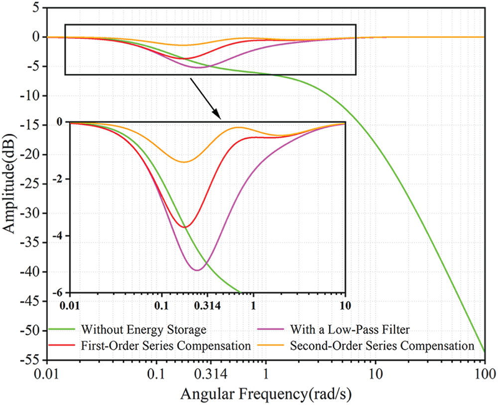
Figure 3: Total output magnitude-frequency characteristics with first-order and second-order series compensation
3.2 Coordinated Control of Thermal-Energy Storage Systems Considering Energy Storage Output Constraints
As the frequency regulation process continues, SOC of the energy storage system may enter an output-constrained region. This could cause the overall frequency response characteristic of the system to fall below that of the thermal power unit without energy storage support, thereby degrading the rapid-response performance of the hybrid frequency regulation system. Therefore, while the energy storage system prioritizes responding to the high-frequency components of the primary frequency regulation command, any portion of high-frequency power that exceeds the available output margin of the energy storage shall be compensated by the thermal power unit. Conversely, if the high-frequency component remains within the storage system’s capability, no compensation from the thermal unit is required. The specific strategy is illustrated in Fig. 4. Where PH denotes the high-frequency component allocated to the energy storage after low-pass filtering, and PL represents the low-frequency component assigned to the thermal power unit.
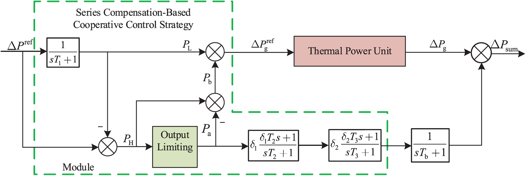
Figure 4: Series compensation-based cooperative control strategy for integrated thermal-energy storage systems
To prevent over-charging or over-discharging of the energy storage system, a Logistic regression function dependent on SOC is introduced in the output limiting module to dynamically constrain the output power. The expression of this function is given by Eq. (30):
where, Pd is the discharging power, Pc is the charging power, Pmax is the maximum output power of the energy storage system, S is the SOC of the energy storage, Smax and Smin are the maximum and minimum allowable SOC values, respectively, and m is a constant.
The input to the output control module is the reference power for the energy storage, PH. The output of the constraint module after limitation, denoted as Pa, is given by Eq. (31):
The compensation value for the high-frequency component to be supplied by the thermal power unit, Pb, is then given by Eq. (32):
Accordingly, the theoretical output command for the thermal power unit, Δ
As observed from Fig. 3, the frequency regulation performance of the system is improved. However, this enhancement is accompanied by an increase in frequency regulation losses. To mitigate these losses, it is necessary to optimize the parameters of the low-pass filter, T1 and the series compensation blocks, T2, T3, δ1, δ2. The objective is to identify a parameter set that simultaneously ensures satisfactory frequency regulation performance and minimizes associated regulation losses.
3.3 System Stability Analysis in Frequency and Time Domains
The stability consideration in this context involves analyzing the closed-loop characteristics of the forward path—from the frequency deviation input to the thermal-storage frequency regulation system, through the regulation power calculation, to the frequency deviation derived from the rotor motion equation. Specifically, the analysis verifies whether this loop satisfies Bode’s first law (i.e., whether the gain slope is –20 dB/dec at the crossover frequency), and assesses whether the gain margin and phase margin of the open-loop transfer function are sufficient.
Strictly speaking, due to the maximum output constraint of the energy storage system in the proposed strategy, the stability analysis can be divided into two typical operating cases:
1. Unconstrained Energy Storage Output: The energy storage operates within its linear region without saturating, and the frequency regulation task assigned to it is not transferred to the thermal power units.
2. Constrained Energy Storage Output: The energy storage is unable to fulfill the entire regulation task due to its output limits. In this case, the control effort from the energy storage path no longer acts linearly, and the frequency-domain characteristics can be approximately dominated by the thermal power path.
For Case 1, since the energy storage operates linearly, the overall system can be regarded as a linear combination of two forward paths. Analysis of the Bode plot of the open-loop transfer function confirms that both the gain margin and phase margin meet stability requirements.
For Case 2, the system effectively reverts to a thermal-power-only frequency regulation mode—a widely adopted configuration in conventional power plants. In this study, this scenario was primarily used to validate the rationality of the setpoints for the thermal power unit’s regulation capacity. Therefore, the necessary linear stability analysis has already been conducted for this operating mode.
As shown in Fig. 5, under unsaturated energy storage conditions, the system exhibits an infinite gain margin, a phase margin of 69.87°, an infinite phase crossover frequency, and a gain crossover frequency of 1.82 rad/s. When the energy storage becomes saturated, the stability margins reduce to a gain margin of 2.92 dB and a phase margin of 39.22°, with corresponding phase and gain crossover frequencies of 4.07 and 2.06 rad/s, respectively.
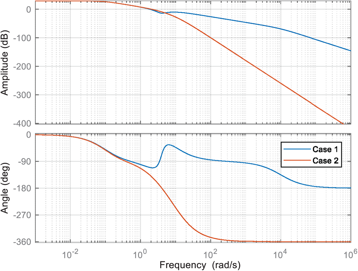
Figure 5: Bode diagrams of the open-loop transfer function of the system under different circumstances
Fig. 6 presents the closed-loop step response of the frequency control system under different operating conditions, demonstrating that the proposed strategy achieves faster response, lower overshoot, and improved stability compared to conventional methods.
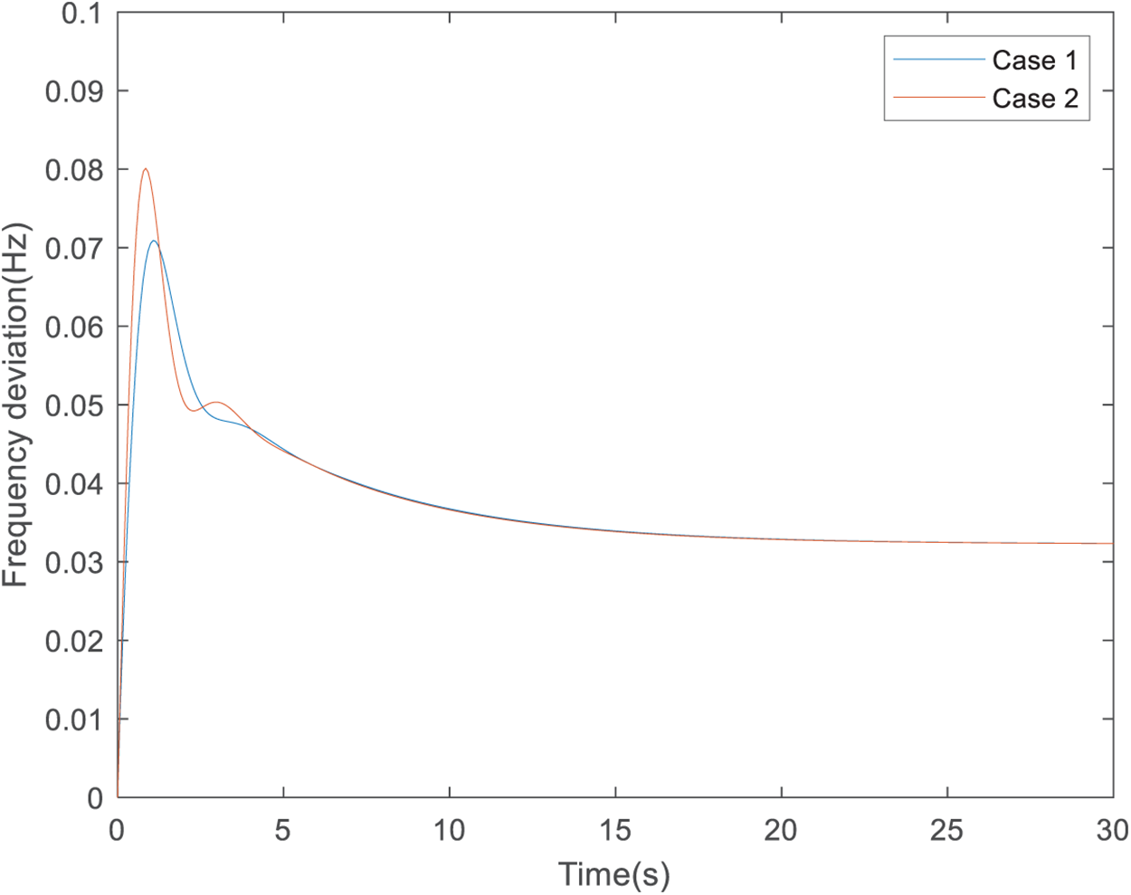
Figure 6: Under different circumstances, the closed-loop step response of the frequency closed-loop control system
4 Tuning of Filter and Compensation Parameters Based on an Improved Particle Swarm Optimization Algorithm
4.1 Objective Function and Constraints
To ensure satisfactory frequency regulation performance while reducing the primary frequency regulation losses of the system, the tuning of parameters, T1, T2, T3, δ1, and δ2 is formulated as an optimization problem. The objective function incorporates both the frequency regulation loss cost and the output performance of the thermal and energy storage systems. Additionally, system output overshoot constraints and parameter bound constraints are taken into account.
where, f1 is the penalty function for system overshoot constraints; f2, f3, f4, f5, f6 are the penalty functions corresponding to the five parameters, respectively; ω0 is the local minimum point of the magnitude-frequency characteristic curve
Based on the calculation methods for frequency regulation losses of the thermal and energy storage systems presented in Section 2.2, the total frequency regulation lifecycle loss costs over the regulation period T for the thermal power unit and the battery storage system, denoted as CTP,T and Cb,T, respectively, are given by Eqs. (35) and (36):
where, Coil, Cgate, Crotor, Chigh, Cmed, and Clow represent the investment costs associated with the oil servomotor, steam valve stem, turbine rotor, high-pressure cylinder, intermediate-pressure cylinder, and low-pressure cylinder, respectively, and CbN denotes the investment cost of the energy storage system.
(1) Overshoot Constraint
(2) Parameter Constraint
where,
4.2 Dynamic Particle Parameter Strategy
Given that the objective function is high-order and nonlinear, employing solvers such as Gurobi may encounter difficulties in modeling and solution. Therefore, the particle swarm optimization (PSO) algorithm, a heuristic method, is selected for parameter optimization. The velocity and position update equations for the particles are given by Eqs. (43) and (44):
where, Jn, c1,n, and c2,n represent the inertia weight and learning factors at the n-th iteration, respectively; r1 and r2 are random numbers uniformly distributed in [0, 1]; pi,j and pg,j denote the best historical position in the j-th dimension of particle i and the entire swarm, respectively; and vi,j(n) and xi,j(n) indicate the velocity and position of particle i in the j-th dimension at the n-th iteration.
To enhance algorithm performance, an improved particle swarm optimization (IPSO) algorithm with dynamic adjustment of J, c1, and c2 is proposed. Specifically, J and c1 decrease linearly over iterations, while c2 increases linearly. In the early evolutionary phase, a larger inertia weight helps maintain strong global exploration capability, whereas a smaller weight in later phases facilitates more precise local exploitation. Regarding the learning factors, a larger c1 accelerates convergence toward individual historical best positions during initial iterations, thereby speeding up early evolution, while a smaller c2 helps preserve swarm diversity. However, in later stages, as the global best approaches the optimum, a larger c2 and smaller c1 are adopted to enhance convergence accuracy by encouraging particles to refine their search near the best solution. The update formulas for Jn, c1,n, and c2,n are given by given by Eqs. (45)–(47):
where, Jmax, Jmin, c1,max, c1,min, c2,max, and c2,min are the maximum and minimum values of J, c1, and c2, respectively; n is the current iteration number; and D is the total number of iterations.
4.3 Algorithm Flowchart and Parameter Tuning Results
Based on the methodologies outlined in Sections 4.1 and 4.2, the flowchart of the IPSO algorithm for parameter optimization is illustrated in Fig. 7. The process begins with the initialization of the particle swarm. Each generated particle is assigned to the parameters T1, T2, T3, δ1, and δ2. The thermal-energy storage primary frequency regulation control system model is then simulated using these parameter sets. Subsequently, the frequency regulation loss cost and the output performance of the system are computed to evaluate the objective function. The algorithm checks whether the convergence criterion is satisfied. If satisfied, the current set of parameters is recorded as the optimal solution; otherwise, the iteration continues until convergence is achieved.
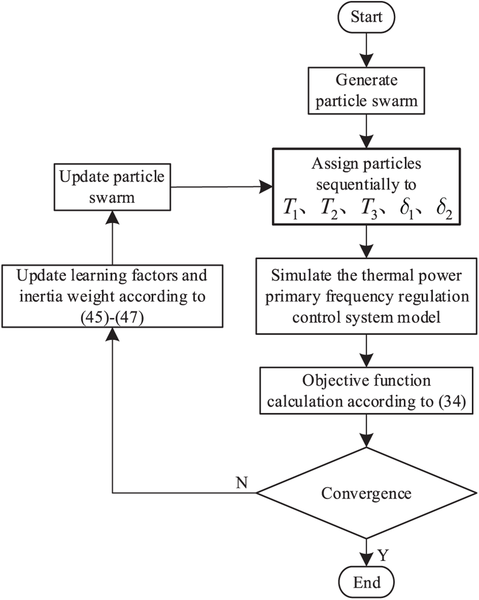
Figure 7: Flowchart of parameter optimization based on the improved particle swarm optimization algorithm
For the parameter optimization process, the total number of particles in the swarm is set to 25. The iteration terminates when the maximum coordinate difference among all particles in the population is less than 0.001. The fitness evolution curve during the parameter tuning process using the IPSO algorithm is shown in Fig. 8, and the parameter optimization trajectories are provided in Fig. 9. As observed, the fitness value gradually decreases and meets the convergence criterion after 256 iterations. Among the parameters, T1 and T2 stabilize after approximately 150 iterations, while T3 stabilizes after about 100 iterations. The final tuned values of the five parameters are: T1 = 1.1389, T2 = 1.1390, T3 = 11.9742, δ1 = 0.6803, and δ2 = 0.2639.
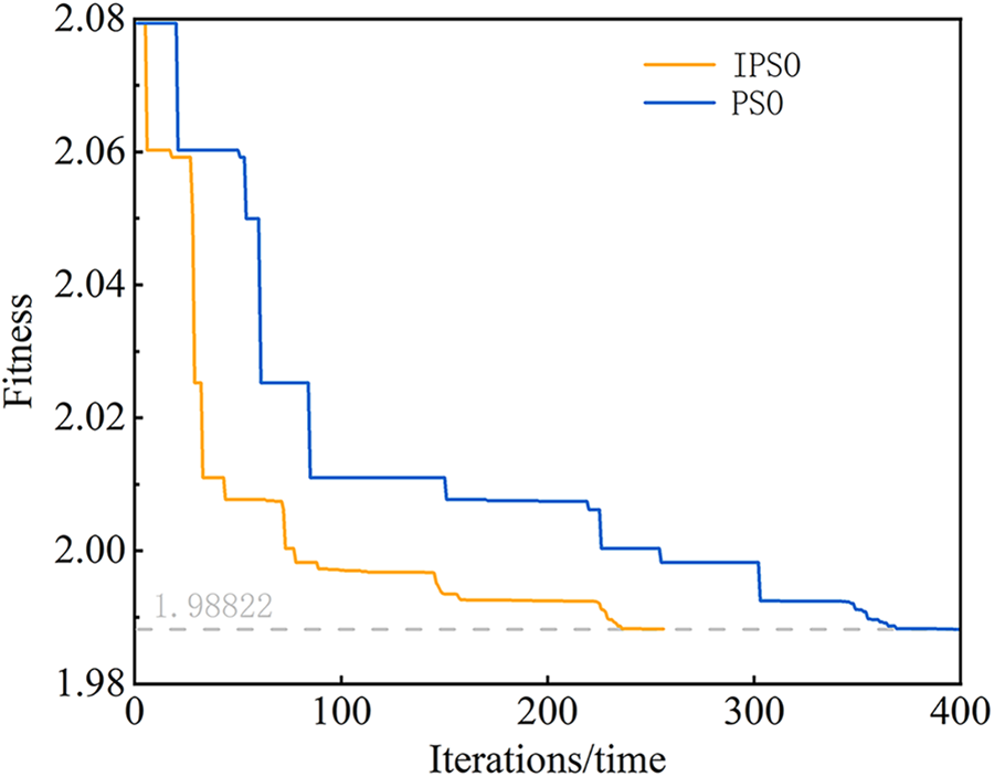
Figure 8: Fitness value evolution curve
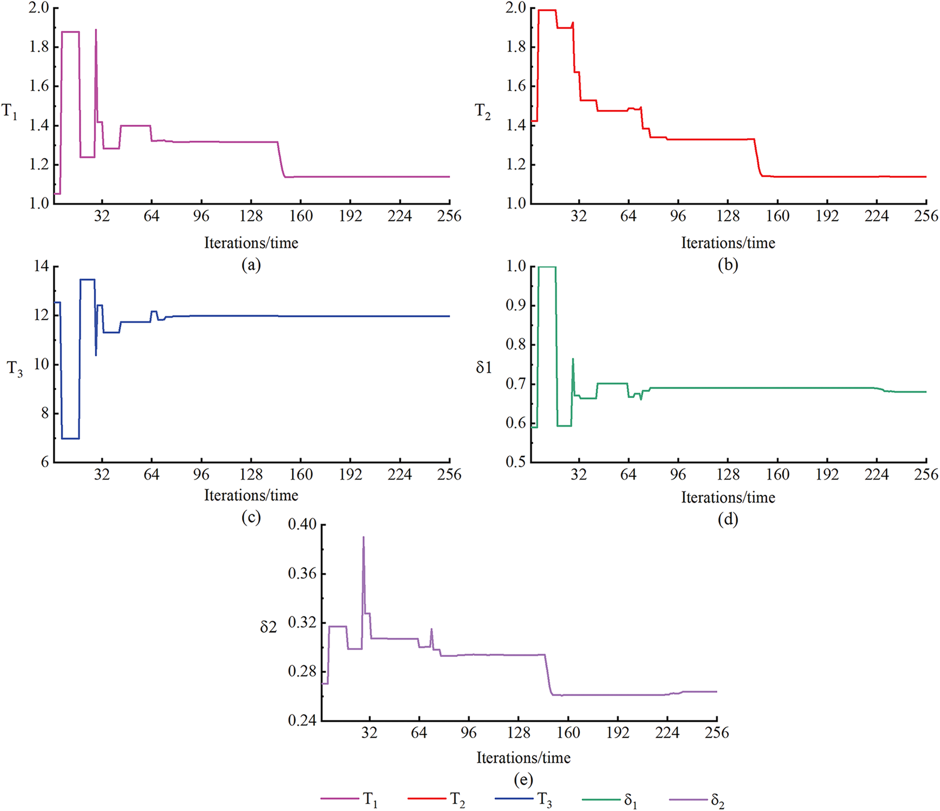
Figure 9: Parameter optimization trajectory
The IPSO demonstrates significantly faster convergence speed and higher solution stability compared to the traditional PSO. The dynamic adjustment mechanism of inertia weights and learning factors in IPSO effectively enhances its global search capability and prevents premature convergence, thereby improving the optimization performance.
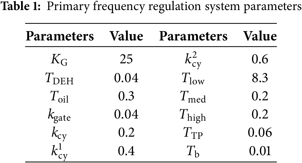
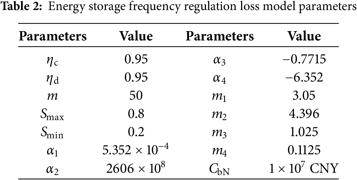
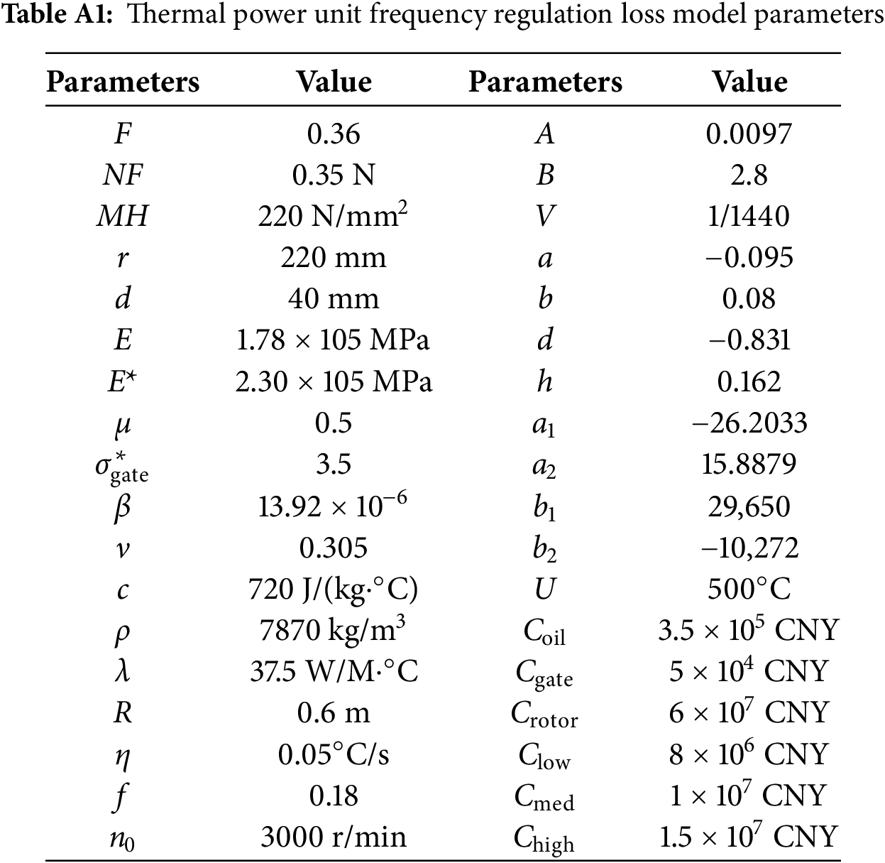
To validate the effectiveness of the proposed control strategy, the following case is established: the rated capacity of the thermal power unit is 350 MW, with a frequency regulation capacity of 10% of its rated value (i.e., 35 MW). The battery energy storage system has a rated power of 10 MW and a rated energy capacity of 10 MW∙2 h. The grid nominal frequency is 50 Hz. The system power base value is set to 350 MW, and the frequency base value is 50 Hz. The primary frequency regulation dead band for both the thermal unit and the energy storage system is set to 0.033 Hz. All other system parameters are normalized according to the per-unit system based on these base values. The specific parameters of the primary frequency regulation system are listed in Table 1, while the relevant parameters for the frequency regulation loss models of the energy storage and thermal power unit are provided in Tables 2 and A1 in Appendix C, respectively. A simulation model for the thermal-energy storage primary frequency regulation is built in the MATLAB/Simulink platform, based on the schematic diagram shown in Fig. 1, which illustrates the participation of the thermal unit and energy storage in the power system’s primary frequency regulation.
To verify the effectiveness of the proposed strategy, the following four control strategies are designed and analyzed under the aforementioned case conditions regarding their frequency regulation performance and system frequency regulation loss costs:
Strategy 1: Only the thermal power unit participates in primary frequency regulation.
Strategy 2: The thermal power unit and the energy storage system share the power through a low-pass filter.
Strategy 3: Based on Strategy 2, a series compensation block is added to the forward path of the energy storage system, with its parameters selected based on empirical values.
Strategy 4: Based on Strategy 2, a series compensation block is added to the forward path of the energy storage system, with its parameters set to the optimized values obtained through the proposed method.
5.1 Frequency Regulation Performance
A 24-h load disturbance profile, as shown in Fig. 10, is selected as the continuous disturbance input to the thermal-energy storage primary frequency regulation system, with a total simulation duration of 24 h. The peak-to-peak value (Δfp−v), average value (Δfaverage), and root mean square value (Δfindex) of the frequency deviation are chosen as evaluation metrics for assessing the frequency regulation performance. These are given by Eq. (48):
where, Δfi represents the grid frequency deviation at the i-th time step.
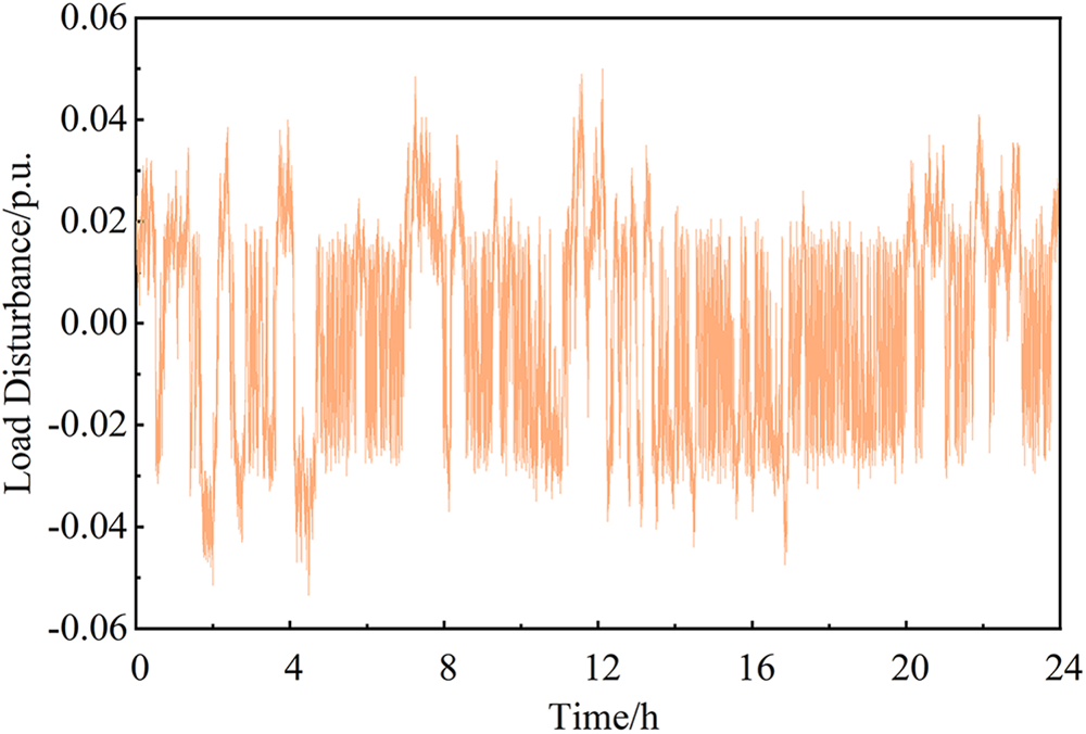
Figure 10: 24-h load disturbance profile
The frequency profiles under Strategy 1 and Strategy 2 are shown in Fig. 11. It can be observed that Strategy 2 reduces the amplitude of the frequency deviation; however, most frequency excursions still remain outside the dead band, indicating limited improvement. Specific frequency evaluation metrics are listed in Table 3. Compared to Strategy 2, Strategy 1 results in a 2.94% increase in the peak-to-peak frequency deviation, a 0.15% decrease in the average deviation, and a 0.024% reduction in the variance. Although the magnitude of frequency fluctuations is similar under both strategies, Strategy 1 clearly leads to larger frequency deviations. Therefore, using a low-pass filter to coordinate the thermal-energy storage system in primary frequency regulation can improve overall system performance and enhance frequency stability.
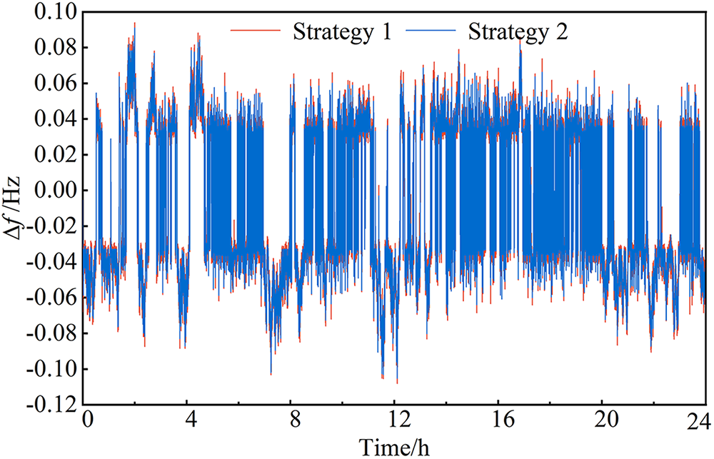
Figure 11: System frequency under strategy 1 and strategy 2
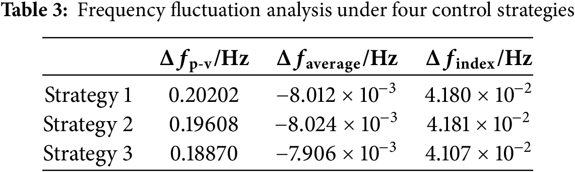
The frequency responses under Strategy 2 and Strategy 3 are compared in Fig. 12. Strategy 3 effectively reduces most frequency deviations within 0.05 Hz into the dead band, particularly during the period from 4 to 20 h where fluctuations are more frequent, resulting in significantly improved performance. Furthermore, compared to Strategy 2, Strategy 3 also slightly reduces lower-magnitude fluctuations above 0.06 Hz. Key evaluation metrics are summarized in Table 3. Specifically, Strategy 3 achieves a 3.91% reduction in the peak-to-peak frequency deviation, a 1.49% decrease in the average deviation, and a 1.80% lower variance compared to Strategy 2. Thus, Strategy 3 incorporating series compensation effectively reduces system frequency deviation, decreases the magnitude of frequency fluctuations, improves frequency regulation performance, and ensures enhanced system frequency stability.
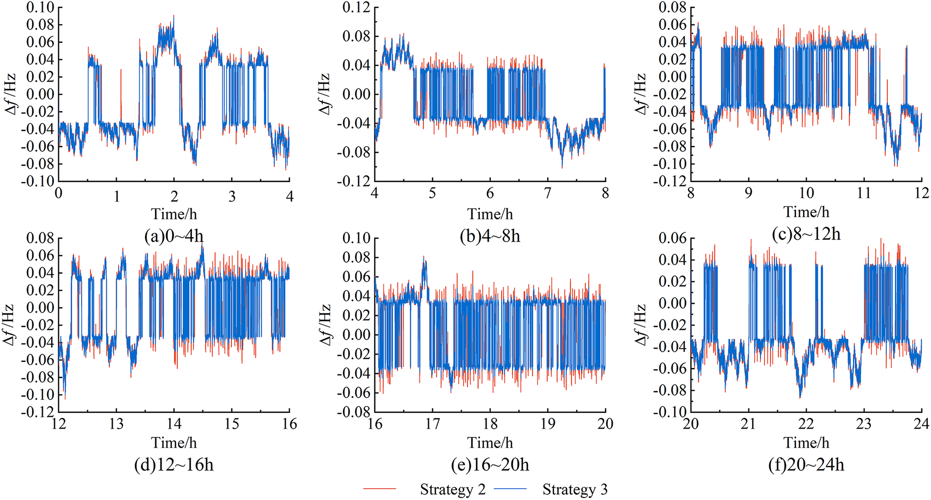
Figure 12: System frequency under strategy 2 and strategy 3: (a) Frequency deviation variation within 0–4 h, (b) Frequency deviation variation within 4–8 h, (c) Frequency deviation variation within 8–12 h, (d) Frequency deviation variation within 12–16 h, (e) Frequency deviation variation within 16–20 h, (f) Frequency deviation variation within 20–24 h
5.2 Frequency Regulation Loss Cost
The variation curves of the frequency regulation loss costs for individual components of the thermal power unit under Strategy 1, as well as the total loss cost, are provided in Fig. 13. The loss costs of the low-pressure, intermediate-pressure, and high-pressure cylinders increase sharply at the beginning of the frequency regulation process, significantly exceeding those of other components and becoming the dominant factors in the overall loss cost of the thermal unit. After 8 h, the loss costs of these three cylinders exhibit a gradual increasing trend, with the low-pressure cylinder incurring the highest cost, followed by the intermediate-pressure and high-pressure cylinders. The loss costs of the oil servomotor, steam valve stem, and rotor increase approximately linearly, with the rotor demonstrating the highest rate of increase, followed by the steam valve stem. These two components surpass the loss cost of the low-pressure cylinder after 4 and 12 h, respectively, becoming the dominant contributors to the total loss cost of the thermal power unit.
Figure 13: Thermal power loss cost under strategy 1: (a) Actuator loss, (b) Throttle valve loss, (c) Lowpressure cylinder loss, (d) Intermediate-pressure cylinder loss, (e) High-pressure cylinder loss, (f) Rotor loss
The frequency regulation loss costs for various components of the thermal power unit under Strategies 2, 3, and 4 are shown in Fig. 14. Compared to Strategy 1, Strategy 2 significantly reduces the loss costs of the oil servomotor, steam valve stem, and cylinders. However, the rotor loss cost remains largely unchanged. Therefore, by reducing the wear on these components, Strategy 2 effectively decreases the daily frequency regulation loss cost of the thermal unit. This demonstrates that coordinating the thermal unit and energy storage via a low-pass filter can reduce the frequency regulation loss cost of the thermal power unit.
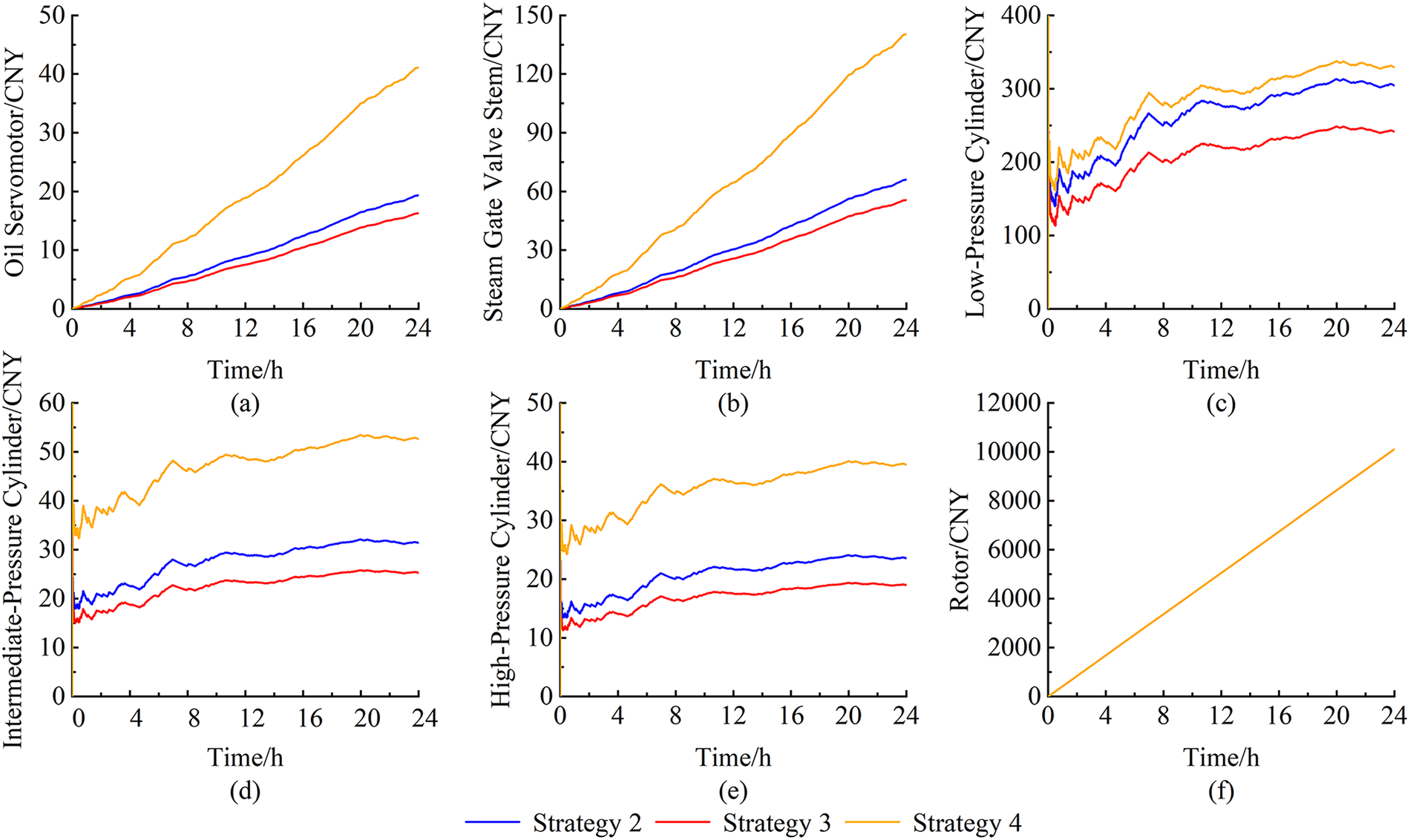
Figure 14: Loss cost breakdown for thermal power components under strategies 2, 3 and 4
As observed in Fig. 14, among Strategies 2, 3, and 4, Strategy 4 results in the highest loss costs for the oil servomotor, steam valve stem, and cylinders, while Strategy 3 yields the lowest. Nevertheless, the differences in these costs among the three strategies are marginal, and all are substantially lower than those under Strategy 1. Additionally, the rotor loss costs under Strategies 2, 3, and 4 are nearly identical and consistent with that of Strategy 1. This is attributed to the fact that the centrifugal stress on the rotor is relatively low, and thus its frequency regulation loss is primarily determined by thermal stress, which is directly related to the duration of frequency regulation. Consequently, both Strategies 3 and 4 also significantly reduce the overall frequency regulation loss cost of the thermal power unit. The total thermal loss costs under Strategies 2, 3, and 4 are comparable, with Strategy 4 exhibiting the highest total cost and Strategy 3 the lowest. The variation process of the total thermal loss cost is illustrated in Fig. 15. Regarding the energy storage loss cost under Strategies 2, 3, and 4, Strategy 3 results in the highest loss, while Strategy 4 yields the lowest, as shown in Fig. 16.
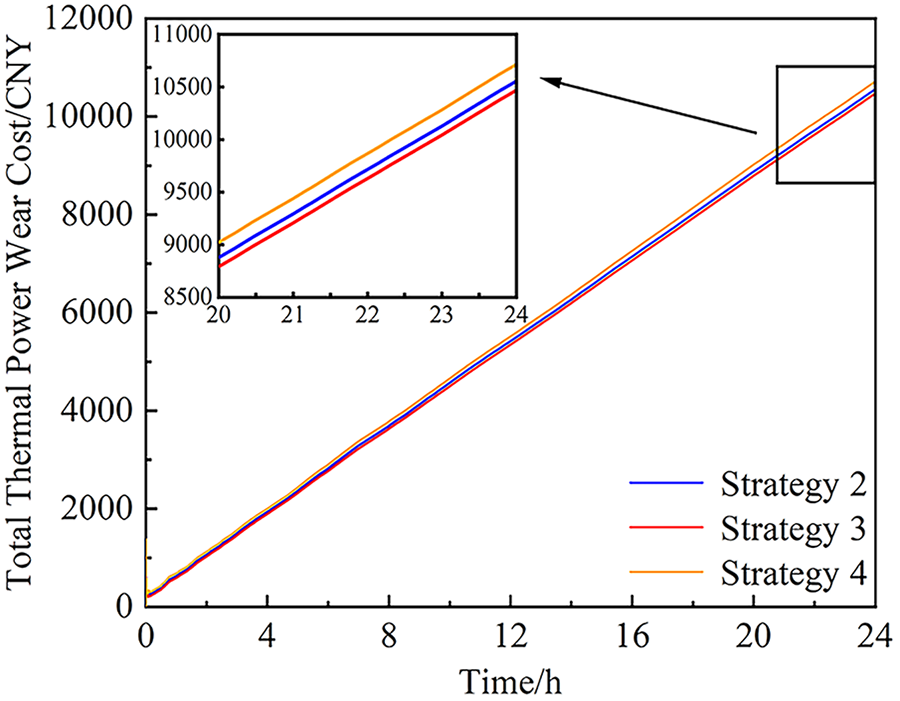
Figure 15: Total thermal power loss cost under strategies 2, 3 and 4
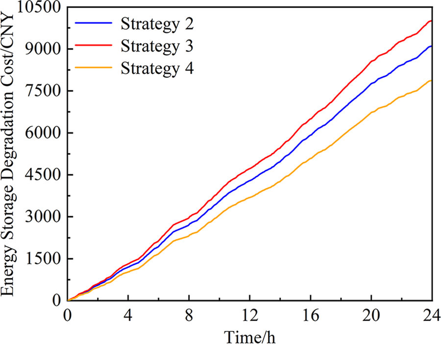
Figure 16: Energy storage loss cost under strategies 2, 3 and 4
A detailed cost analysis for the thermal and energy storage systems is presented in Table 4. Compared to Strategy 1, although Strategies 2 and 3 reduce the frequency regulation loss cost of the thermal power unit, the total system loss cost increases by 6.13% and 10.57%, respectively. In contrast, Strategy 4 not only reduces the thermal unit’s loss cost but also limits the increase in the total system loss cost to only 0.34% relative to Strategy 1, making it nearly equivalent to the total loss cost incurred when only the thermal unit participates in frequency regulation. Thus, Strategy 4 effectively reduces the thermal unit’s loss cost while maintaining the overall system loss cost at a acceptable level.
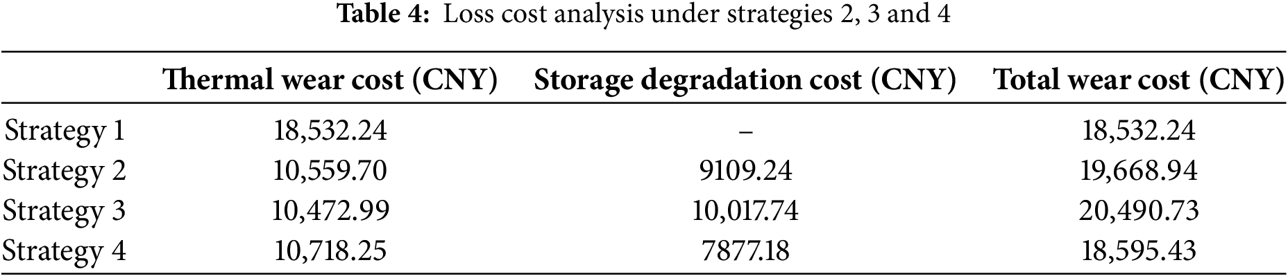
Although Strategy 3 results in a slight reduction in the thermal unit’s loss cost compared to Strategy 2, and Strategy 4 leads to a marginal increase relative to Strategy 2, the total daily energy storage loss cost under Strategies 3 and 4 increases by 9.97% and decreases by 13.53%, respectively, compared to Strategy 2. Consequently, the total daily system frequency regulation loss cost under Strategies 3 and 4 increases by 4.18% and decreases by 5.77%, respectively, relative to Strategy 2, resulting in Strategy 4’s total loss cost being comparable to that of Strategy 1. This behavior can be attributed to the fact that Strategy 3 incorporates a series compensation block with empirically selected parameters in the forward path of the energy storage system, which increases the output of the energy storage system. On the other hand, Strategy 4 utilizes parameters tuned by the improved Particle Swarm Optimization algorithm. Although this approach increases the output of the thermal power unit compared to Strategy 2, it significantly reduces the loss cost of the energy storage system, thereby lowering the total system loss cost.
Furthermore, under Strategy 4, the system frequency deviation exhibits a peak-to-peak value of 0.18796 Hz, an average value of –7.893 × 10⁻³ Hz, and a variance of 4.103 × 10⁻² Hz. These values represent reductions of 0.39%, 0.16%, and 0.1%, respectively, compared to Strategy 3. In addition, the total system frequency regulation loss cost under Strategy 4 is 9.25% lower than that under Strategy 3. Therefore, Strategy 4 not only enhances the economic efficiency of the system but also ensures its frequency stability.
5.3 Frequency Regulation Loss Cost
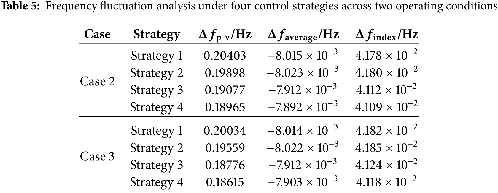
In terms of frequency regulation performance, Strategy 4 consistently achieves the best frequency metrics across all three configurations (200, 350, and 500 MW). It yields the smallest frequency peak-to-peak deviation, a mean value closest to zero, and the lowest variance. These results confirm that the proposed control strategy effectively suppresses frequency fluctuations and enhances grid stability, with its superior performance being robust to changes in system scale, which is given by Table 5.
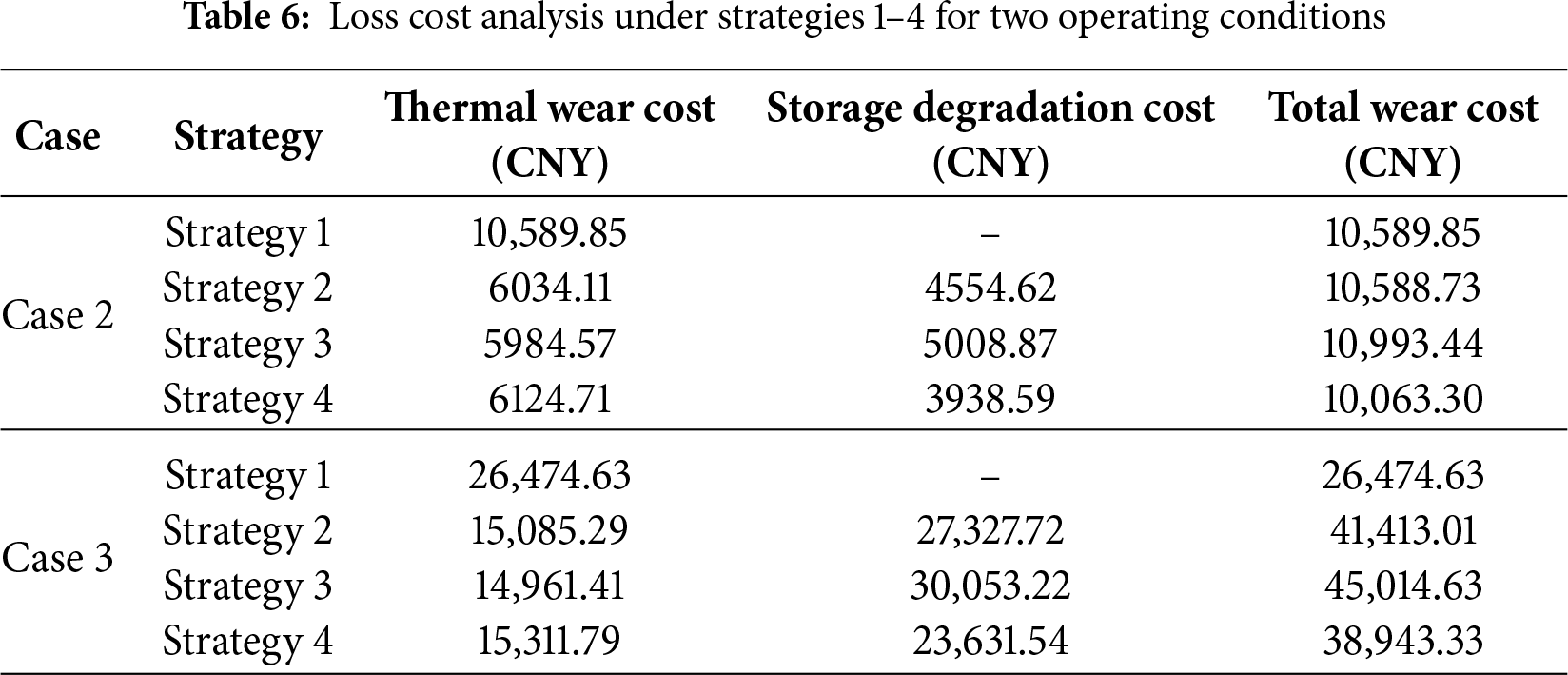
In terms of economic performance, an shown in Table 6, Strategy 4 also demonstrates excellent results. It achieves relatively low total loss costs under the 200 MW configuration, matches nearly the minimum cost in the 350 MW baseline scenario, and maintains significantly lower costs compared to other energy storage participation strategies even in the 500 MW large-scale configuration. These findings indicate that Strategy 4 successfully achieves an optimal balance between high performance and low cost.
In summary, Strategy 4 demonstrates the capability to simultaneously deliver optimal frequency regulation performance and maintain competitive economic efficiency across system configurations of varying scales, highlighting its substantial value for engineering applications. Characterized by wide applicability and strong robustness against system parameter variations, the proposed strategy presents a reliable and efficient solution for integrated thermal-storage frequency regulation systems.
Addressing the challenge of improving the primary frequency regulation performance of a combined thermal-storage system while reducing system regulation loss, this paper proposed a multi-dimensional cooperative optimization strategy for the control parameters of a thermal-storage combined system that accounts for regulation loss. Simulation studies lead to the following conclusions:
(1) The proposed loss calculation methods for various components of the thermal power unit and the energy storage system can effectively quantify their respective losses during frequency regulation operation, providing an accurate basis for loss assessment.
(2) The series compensation-based cooperative control strategy enhances system frequency regulation performance. Compared to Strategy 2, the peak-to-valley frequency deviation, variance, and mean under Strategy 3 decreased by 3.76%, 1.77%, and 1.47%, respectively, thereby improving system frequency stability.
(3) The parameter tuning strategy based on the improved PSO algorithm achieves a better balance between regulation performance and economy. Compared to Strategy 3, the total system regulation loss cost under Strategy 4 is reduced by 9.25%, reaching a level comparable to Strategy 1, while the thermal power loss cost is significantly reduced by 42.16% compared to Strategy 1. Furthermore, the frequency regulation performance under Strategy 4 is slightly superior to that of Strategy 3.
This study provides a theoretical foundation and practical guidance for balancing frequency regulation performance and regulation loss in power systems with a high penetration of renewable energy, demonstrating its value and development potential. However, it currently focuses solely on the regulation loss of thermal units and energy storage during primary frequency regulation, without considering the compensation benefits and penalties within the ancillary service market. Future research will incorporate frequency regulation compensation revenues and penalties derived from market assessment metrics, based on detailed regulation rules, to further optimize the economic dispatch of the thermal-storage frequency regulation system, thereby enhancing the comprehensive application value of the proposed methodology.
Acknowledgement: This research was supported by the Key Laboratory of Modern Power System Simulation and Control & Renewable Energy Technology, Ministry of Education (Northeast Electric Power University), and the Science and Technology Development Project of Jilin Province, which provided funding, technical support, and data resources. We have confirmed that all acknowledged individuals and organizations have consented to being recognized for their contributions, which have been invaluable in advancing the goals of this study.
Funding Statement: This study was supported by the Science and Technology Development Project of Jilin Province (Project No. YDZJ202301ZYTS284).
Author Contributions: The authors confirm contribution to the paper as follows: study conception, task division, content planning, model development, simulation validation, and draft manuscript preparation: Zezhong Liu, Jinyu Guo; project introduction, progress and direction oversight, data support, practical validation, funding acquisition, and final manuscript review: Xingxu Zhu, Junhui Li. All authors reviewed the results and approved the final version of the manuscript.
Availability of Data and Materials: Due to the nature of this research, the data are restricted by confidentiality clauses in contracts and legal regulations, so supporting data is not available.
Ethics Approval: Not applicable.
Conflicts of Interest: The authors declare no conflicts of interest to report regarding the present study.
Abbreviations
| DOD | Depth of discharge |
| SOC | State of charge |
| FLPF | First-order low-pass filter |
| PSO | Particle swarm optimization |
| IPSO | Improved particle swarm optimization |
The losses of the steam turbine rotor during frequency regulation primarily include low-cycle fatigue damage and creep damage. Both types of damage are related to the stress experienced by the rotor during unit start-ups/shut-downs or frequent load variations. This stress comprises thermal stress, caused by severe temperature fluctuations during operation, and centrifugal tangential stress due to rotation. Therefore, it is essential to first calculate the thermal stress and centrifugal tangential stress acting on the rotor to determine its frequency regulation loss.
(1) Rotor Thermal Stress
To simplify the calculation, a one-dimensional analytical method is employed to obtain the rotor thermal stress. The formula for rotor thermal stress is given by Eqs. (A1) and (A2):
where, σth,t is the rotor thermal stress (MPa) at time t, β is the coefficient of linear expansion of the rotor material, υ is Poisson’s ratio of the rotor material, c is the specific heat of the rotor material (J/kg·°C), ρ is the density of the rotor material (kg/m3),
(2) Rotor Centrifugal Tangential Stress
The centrifugal tangential stress on the rotor is given by Eqs. (A3) and (A4):
where, σc,t is the centrifugal tangential stress (MPa) at time t, nt is the rotor speed at time t, σ0 and n0 are the rated centrifugal tangential stress and rated speed, respectively, ω is the rated angular velocity.
The equivalent von Mises stress σeq,t at time t is then given by Eq. (A5) based on the fourth strength theory:
The total strain Δεt at time t is given by Eq. (A6):
Considering material hardness, a modified Manson-Coffin relationship between total strain and the number of cycles to crack initiation is given by Eq. (A7):
where, V is the alternating frequency of the stress, A, B, a, b, d, h are time constants, Nt is the number of cycles to crack initiation at time t [24].
Based on creep experimental results, the relationship between the Larson-Miller parameter P, hardness, and stress is given by Eq. (A8) [25]:
where, a1, b1, a2, b2 are time constants.
The parameter P is related to the creep rupture time, which can be given by Eq. (A9):
where,
The total frequency regulation loss of the turbine rotor at time t, Lrotor,t representing the combined low-cycle fatigue and creep damage, is given by Eq. (A10):
The life consumption of the steam turbine cylinders is primarily related to the steam admission flow. Therefore, the life consumption of the cylinders is determined by calculating the steam admission flow through the high-pressure, intermediate-pressure, and low-pressure cylinders. Thus, the total steam admission flow ΔScy,t, during frequency regulation at time t, along with the respective flows for the high-pressure cylinder ΔShigh,t, intermediate-pressure cylinder ΔSmed,t, and low-pressure cylinder ΔSlow,t, are given by Eqs. (A11)–(A14):
Thus, the cylinder loss can be given by Eqs. (A15)–(A17):
where, Lhigh,T, Lmed,T, and Llow,T represent the life consumption of the high-pressure, intermediate-pressure, and low-pressure cylinders, respectively, over the frequency regulation period T. Shigh,t, Smed,t, and Slow,t denote the required steam flow rates for the high-pressure, intermediate-pressure, and low-pressure cylinders, respectively, during normal operation at time t. For the timescale of frequency regulation, the steam flow rate for each cylinder is considered approximately constant [20].
References
1. Ren J, Tian W, Gao G, Yao P, Xin C, Ye M, et al. Day-ahead scheduling model for high-penetration renewable energy power system considering energy storage for auxiliary peak shaving and frequency regulation. IEEE Access. 2025;13:50480–92. doi:10.1109/access.2025.3552758. [Google Scholar] [CrossRef]
2. Zhang X, Tan T, Yu T, Yang B, Huang X. Bi-objective optimization of real-time AGC dispatch in perfor-mance-based frequency regulation market. CSEE J Power Energy Syst. 2024;10(6):2360–70. doi:10.17775/cseejpes.2020.01860. [Google Scholar] [CrossRef]
3. Zhang X, Ma Z, Gu B, Fang L, Yu X. On BESS capacity optimization of hybrid coal-fired generator and BESS power station for secondary frequency regulation. IEEE Access. 2025;13:60833–45. doi:10.1109/ACCESS.2025.3557853. [Google Scholar] [CrossRef]
4. Liu L, Hu Z, Mujeeb A. Automatic generation control considering uncertainties of the key parameters in the frequency response model. IEEE Trans Power Syst. 2022;37(6):4605–17. doi:10.1109/tpwrs.2022.3153509. [Google Scholar] [CrossRef]
5. Li Z, Cheng Z, Wang Y, Sui Q. Distributed event-triggered fixed-time SMC-based AGC for power systems with heterogeneous frequency regulation units. IEEE Trans Ind Inform. 2024;20(5):8031–43. doi:10.1109/TII.2024.3367003. [Google Scholar] [CrossRef]
6. Xue S, Zeng S, Song Y, Hu X, Liang J, Qing H. Adaptive secondary frequency regulation strategy for energy storage based on dynamic primary frequency regulation. IEEE Trans Power Deliv. 2024;39(6):3503–13. doi:10.1109/tpwrd.2024.3485121. [Google Scholar] [CrossRef]
7. Desingu K, Selvaraj R, Kumar BA, Chelliah TR. Thermal performance improvement in multi-megawatt power converters serving to asynchronous hydro generators operating around synchronous speed. IEEE Trans Energy Convers. 2021;36(3):1818–30. doi:10.1109/tec.2020.3037244. [Google Scholar] [CrossRef]
8. Diao R, Hu Z, Song Y, Mujeeb A, Liu L. Cooperation mode and operation strategy for the union of thermal generating unit and battery storage to improve AGC performance. IEEE Trans Power Syst. 2023;38(6):5290–301. doi:10.1109/tpwrs.2022.3231044. [Google Scholar] [CrossRef]
9. Li C, Li J, Li J, Zhang X, Hou T. Optimization strategy of secondary frequency modulation based on dynamic loss model of the energy storage unit. J Energy Storage. 2022;51:104425. doi:10.1016/j.est.2022.104425. [Google Scholar] [CrossRef]
10. Stecca M, Soeiro TB, Elizondo LR, Bauer P, Palensky P. Lifetime estimation of grid-connected battery storage and power electronics inverter providing primary frequency regulation. IEEE Open J Ind Electron Soc. 2021;2:240–51. doi:10.1109/ojies.2021.3064635. [Google Scholar] [CrossRef]
11. Liang JY, Yuan Z, Wang WQ, Li J. Comprehensive adaptive primary frequency control strategy based on battery energy storage system. Trans China Electrotech Soc. 2025;40(7):2322–34. (In Chinese). doi:10.19595/j.cnki.1000-6753.tces.240456. [Google Scholar] [CrossRef]
12. Liu H, Zhang C, Peng X, Zhang S. Configuration of an energy storage system for primary frequency reserve and inertia response of the power grid. IEEE Access. 2021;9:41965–75. doi:10.1109/access.2021.3065728. [Google Scholar] [CrossRef]
13. Xiao J, Li P, Mao Z, Tu C. Hierarchical coordinated control strategy for enhanced performance of energy storage system in secondary frequency regulation. IEEE Trans Sustain Energy. 2025;16(3):1874–88. doi:10.1109/tste.2025.3540599. [Google Scholar] [CrossRef]
14. Ma Q, Wei W, Wu L, Mei S. Life-aware operation of battery energy storage in frequency regulation. IEEE Trans Sustain Energy. 2023;14(3):1725–36. doi:10.1109/tste.2023.3245197. [Google Scholar] [CrossRef]
15. Li C, Wang X, Li J, Zhu X, Yan G, Jia C. Multi-constrained optimal control of energy storage combined thermal power participating in frequency regulation based on life model of energy storage. J Energy Storage. 2023;73:109050. doi:10.1016/j.est.2023.109050. [Google Scholar] [CrossRef]
16. Cheng B, Powell WB. Co-optimizing battery storage for the frequency regulation and energy arbitrage using multi-scale dynamic programming. IEEE Trans Smart Grid. 2018;9(3):1997–2005. doi:10.1109/TSG.2016.2605141. [Google Scholar] [CrossRef]
17. Liu H, Zhang P, Xing H. Research on primary frequency regulation control strategy of flywheel energy storage assisted thermal power unit based on VMD decomposition. IET Conf Proc. 2023;2023(15):784–90. doi:10.1049/icp.2023.2263. [Google Scholar] [CrossRef]
18. Marimuthu P, Rajesh T, Rajeswaran N, Alhelou HH. Comparative performance analysis of deregulated hydrothermal system with dual mode controller and diverse source of generation employing imperialistic competition algorithm. IEEE Access. 2022;10:51008–20. doi:10.1109/ACCESS.2022.3172109. [Google Scholar] [CrossRef]
19. Singh K, Amir M, Ahmad F, Khan MA. An integral tilt derivative control strategy for frequency control in multimicrogrid system. IEEE Syst J. 2021;15(1):1477–88. doi:10.1109/jsyst.2020.2991634. [Google Scholar] [CrossRef]
20. Liu X, Xu X, Wu Q, Chen X, Wen J, Wang W, et al. SoC threshold optimization for battery storage in frequency regulation considering uncertainty of SoC measurement and automatic generation control fatigue loss of thermal power system. Int J Electr Power Energy Syst. 2022;137:107771. doi:10.1016/j.ijepes.2021.107771. [Google Scholar] [CrossRef]
21. Li S, Zhao P, Gu C, Xiang Y, Bu S, Chung E, et al. Factoring electrochemical and full-lifecycle aging modes of battery participating in energy and transportation systems. IEEE Trans Smart Grid. 2024;15(5):4932–45. doi:10.1109/tsg.2024.3402548. [Google Scholar] [CrossRef]
22. Li S, Zhao P, Gu C, Li J, Huo D, Cheng S. Aging mitigation for battery energy storage system in electric vehicles. IEEE Trans Smart Grid. 2023;14(3):2152–63. doi:10.1109/tsg.2022.3210041. [Google Scholar] [CrossRef]
23. Liang Z. Variable conditions optimization and life prediction research on 600MW steam turbine [master’s thesis]. Hebei, China: North China Electric Power University; 2014. (In Chinese). [Google Scholar]
24. Sun C. Stress and life online monitor of the driving pump turbine [master’s thesis]. Beijing, China: North China Electric Power University; 2003. (In Chinese). [Google Scholar]
25. Dai X. The study of life wastage and life forecast of steam turbine rotor [master’s thesis]. Hebei, China: North China Electric Power University; 2007. (In Chinese). [Google Scholar]
Cite This Article
 Copyright © 2026 The Author(s). Published by Tech Science Press.
This work is licensed under a Creative Commons Attribution 4.0 International License , which permits unrestricted use, distribution, and reproduction in any medium, provided the original work is properly cited.
 Downloads
 Citation Tools