
 Submit a Paper
 Propose a Special lssue
 Open Access
ARTICLE

CFD-Based Optimization of a Diesel Engine Waste Heat Recycle System
School of Energy and Power Engineering, Shandong University, Jinan, 250061, China
* Corresponding Authors: Ke Sun. Email: ; Guoxiang Li. Email:
(This article belongs to the Special Issue: Recent Advances in Fluid Mechanics and Thermal Sciences II)
Fluid Dynamics & Materials Processing 2023, 19(6), 1479-1493. https://doi.org/10.32604/fdmp.2023.022634
Received 18 March 2022; Accepted 09 September 2022; Issue published 30 January 2023
 View Full Text
 Download PDF
Abstract
A dedicated heat exchanger model is introduced for the optimization of heavy-duty diesel engines. The model is a prerequisite for the execution of CFD simulations, which are used to improve waste heat recovery in these systems. Several optimization methods coupled with different types of working fluids are compared in terms of exergy efficiency and heat exchanger complicity. The three considered optimization methods all lead to significant improvements in the R245fa and R1233zd systems with a comparatively low evaporation temperature. The optimal R245fa system has the highest efficiency increase (77.49%). The cyclopentane system displays the highest effi- ciency among the optimized ORC (Organic Rankine Cycle) systems, yet achieved by using a much heavier evaporator HEC (Heat Exchanging Core). In contrast, the 96.84% efficiency increase for the optimized R1233zd is achieved with only 68.96% evaporator weight.Keywords
Nomenclature
| A | Heat exchanging area, m2 |
| d | Diameter, mm |
| G | k-ω generation (-) |
| h | Enthalpy, kJ/kg |
| K | Heat transfer coefficient, W/m2·K |
| k | Turbulence kinetic energy, J |
| m | Mass, kg |
| Nu | Nusselt number (-) |
| Pr | Prandtl number (-) |
| Q | Heat flux, kW |
| Re | Reynolds number (-) |
| s | Distance, mm |
| a | Low-Reynolds-Number coefficient (-) |
| Γ: | Effective diffusivity (-) |
| μ: | Turbulent viscosity, m2/s |
| η: | Efficiency, % |
| ω: | Specific dissipation rate |
| Acronyms | |
| CFD | Computational Fluid Dynamics |
| CO2 | Carbon Dioxide |
| EGR | Exhaust Gas Recirculation |
| eva | Evaporator |
| exp | Expander |
| HEC | Heat Exchanging Core |
| LMTD | Log-Mean Temperature Difference |
| ORC | Organic Rankine Cycle |
| x | Exergy |
Transportation contributed a large proportion of the total greenhouse gas emission each year, of which road transportation has the highest energy consumption amount [1]. The carbon dioxide emissions of road vehicles, including trucks using heavy-duty diesel engines, require further optimization. Waste heat recovery using organic Rankine cycle (ORC) is a cheap and effective way to reduce CO2 emissions. For road vehicles, the ORC system also requires considerations of compact and robustness, alongside high-efficiency. A simple diesel engine exhaust ORC system is shown in Fig. 1. After the clarification process within the system, exhaust flows into the evaporator of the ORC system as heat source. Liquid working fluid exchanges heat with the exhaust and evaporate. The expander generates power from the high-pressure working fluid steam and transforms heat into kinetic energy. After expansion, low-pressure gas condenses in the condenser, cooled liquid flows back to the fluid tank, and the pump compresses the fluid for another cycle.
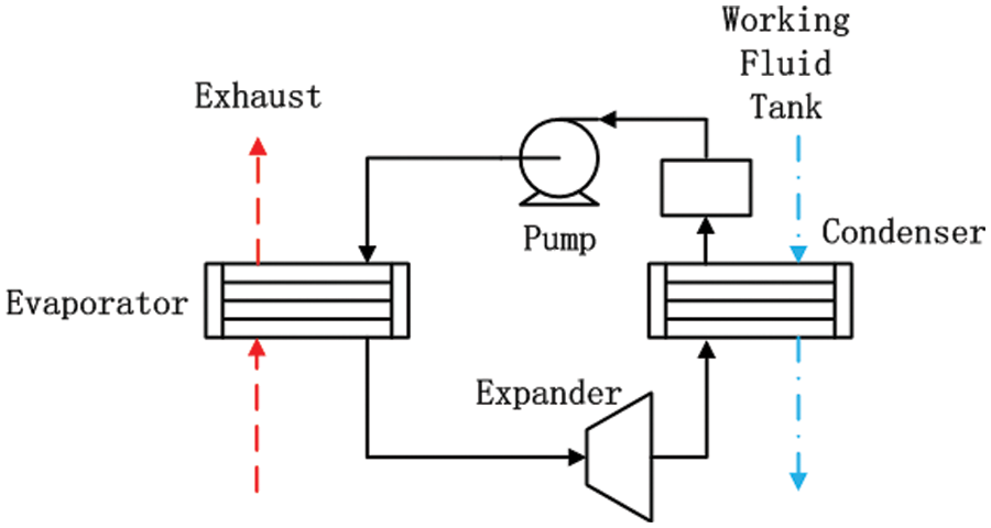
Figure 1: ORC system structure
Therefore, heat exchangers, especially the evaporator, determine the quantity of recovered energy and affect its quality, thus critical to the ORC system. The detailed analysis of Holik et al. [2] focused on the tube-fin heat exchangers of the ORC system; the heat exchanger complicity in terms of heat exchanging area is one of the two major concerns, beside the system power output; the research also pointed out that tube-fin heat exchanger with high-pressure sustainability is ideal for high-efficiency ORC systems to recover waste heat from engine exhaust. Liu et al. [3] optimized the tube-fin heat exchanger of a diesel engine exhaust ORC system. The optimization decreased the total annual cost by 71.46%, beside other improvements in pressure drop and volume. Mastrullo et al. [4] modeled shell and louvered fin mini-tube heat exchangers and optimized them for application in an ORC system of heavy-duty diesel truck engine. Shu et al. [5] established a cascade ORC system using tube-fin heat exchangers, and further calculated the capital cost of the ORC system, including the exhaust evaporator [6]. It should be noted, furthermore, that plate-fin exchangers have the advantage in compactness and efficiency, though many problems remained to be solved during their utilization. Mavridou et al. [7] analyzed various heat exchangers designs including a plate-fin heat exchanger, and discussed related difficulties. The analysis of this paper will focus on tube-fin exchangers.
The thermal efficiency of the ORC system is largely determined by the expansion ratio within the expander. With the evaporate pressure and the condense temperature remaining constant, the expansion ratio is determined by condense temperature thus, working fluid with lower condense pressure has better thermal efficiency. On the other hand, working fluid with lower condense pressure usually has higher evaporate temperature; comparatively low-temperature differences within the evaporator requires more heat exchanging area, which further increases the weight and the capital cost. The exhaust temperature of the diesel engine is considerably lower than the gasoline engine. Therefore, working fluids with extremely high evaporate temperature, such as water, benzene and toluene, are less effective due to evaporate pressure limitation and will not be taken into further comparison. Working fluids with moderately high evaporate temperature, such as ethanol [5,8], cyclopentane [9] and cyclohexane [10], have better performance in terms of the ORC system output and capital cost. Working fluids with lower evaporate temperatures, such as R245fa [3,4] and R1233zd [11,12] have also been analyzed in various experimental ORC systems. The CO2 transcritical ORC system of Li et al. [13] has the advantage of extremely low cycle temperature; different waste heat sources can be absorbed within a single cycle. However, the high operating pressure of the system is difficult to achieve.
The scheme of the ORC system varies greatly in terms of heat sources. Besides engine exhaust, utilizing waste heat from the coolant, the exhaust gas recirculation (EGR) cooler and the charge intercooler have also been taken into experimental consideration and possible application. Coolant contained a large quantity of waste heat with limited quality, the usage of the coolant waste heat and other low-quality heat sources can be difficult in applications. Lu et al. [14] designed a serial ORC system using waste heat from both the coolant and the engine exhaust, and optimized four different system layouts. A parallel ORC system, or even a cascade ORC system, can achieve higher system efficiency at the cost of a complex and expansive system. Shu et al. [5] applied two different working fluids to achieve higher system efficiency and power output, while Chen et al. [9] proposed a cascade ORC system with only cyclopentane as working fluid. The ethanol system of Freymann et al. [15] and the R245fa system of Amicabile et al. [16] both applied a separate EGR superheater. However, the operation temperature of EGR is much higher than the diesel engine exhaust. Lu et al. [14] pointed out that the superheating temperature has limited influence on certain ORC system schemes. The complicated scheme in Li et al. [13] utilized multiple heat sources and applied several separate heat exchangers for recycling.
The evaporator affects the ORC system performance, the simple system of Holik et al. [2] and the cascade system of Shu et al. [5] have given much attention to both system output and capital cost. However, the system also affects the evaporator requirement; this relationship between the two can be further investigated. Therefore, to further improve the total efficiency of a heavy-duty truck diesel engine, a heat exchanger simulation model is constructed and coupled with an ORC system model to investigate the effect of other related factors on the evaporator and the system efficiency. Other major aspects of the ORC system, such as the evaporation pressure, the condenser parameter, and the system scheme are considered and analyzed. Li et al. [17] selected five typical working fluids for optimization.
This paper’s objective is to increase the exergy efficiency of the ORC system while containing the system weight at an appropriate level for road vehicles. This work analyzed various factors that affect the evaporator and the ORC system output, namely evaporation pressure, condensing temperature and supercooling degree, and preheating system schemes. Different working fluids are also compared within the process. The major consideration is to evaluate the ORC system complicity (in terms of heat exchanging area and weight) increase along with system efficiency increase and achieve high system output with a limited weight increase. The comprehensive analysis is both a supplement of former research, and a suggestion for future application and optimization.
The heat absorption process of the ORC system can be divided in to preheating, evaporation and superheating. The evaporation process requires a heat source with both high quality and large quantity, and the evaporate temperature largely determines the thermal efficiency of the ORC system. The low-temperature fluid of the preheating process can absorb waste heat from low-quality heat sources such as the coolant and the charge inter cooler, and the superheating requires heat source with a high energy quality instead of a large energy quantity, thus the EGR cooler is ideal for superheating. The heat source of the ORC system model is generalized into two parts, low-quality heat sources and the engine exhaust. The engine exhaust exchanges heat within the evaporator, and low-quality heat sources exchange heat before the evaporator. The EGR waste heat is not considered in this paper, mainly because of practical difficulties such as high temperature lubrication and heat exchanger reliability.
A simplified ORC system model has been constructed for thermal and exergy efficiency analysis, with the system structure shown in Fig. 1. The heat flux in the evaporator can be defined as Eq. (1):
where ms stands for mass flow of heat source and working fluid, mr stands for mass flow,
Methods that increase system output either increase the system efficiency or increase the system energy input, as defined as Eq. (2):
where
where
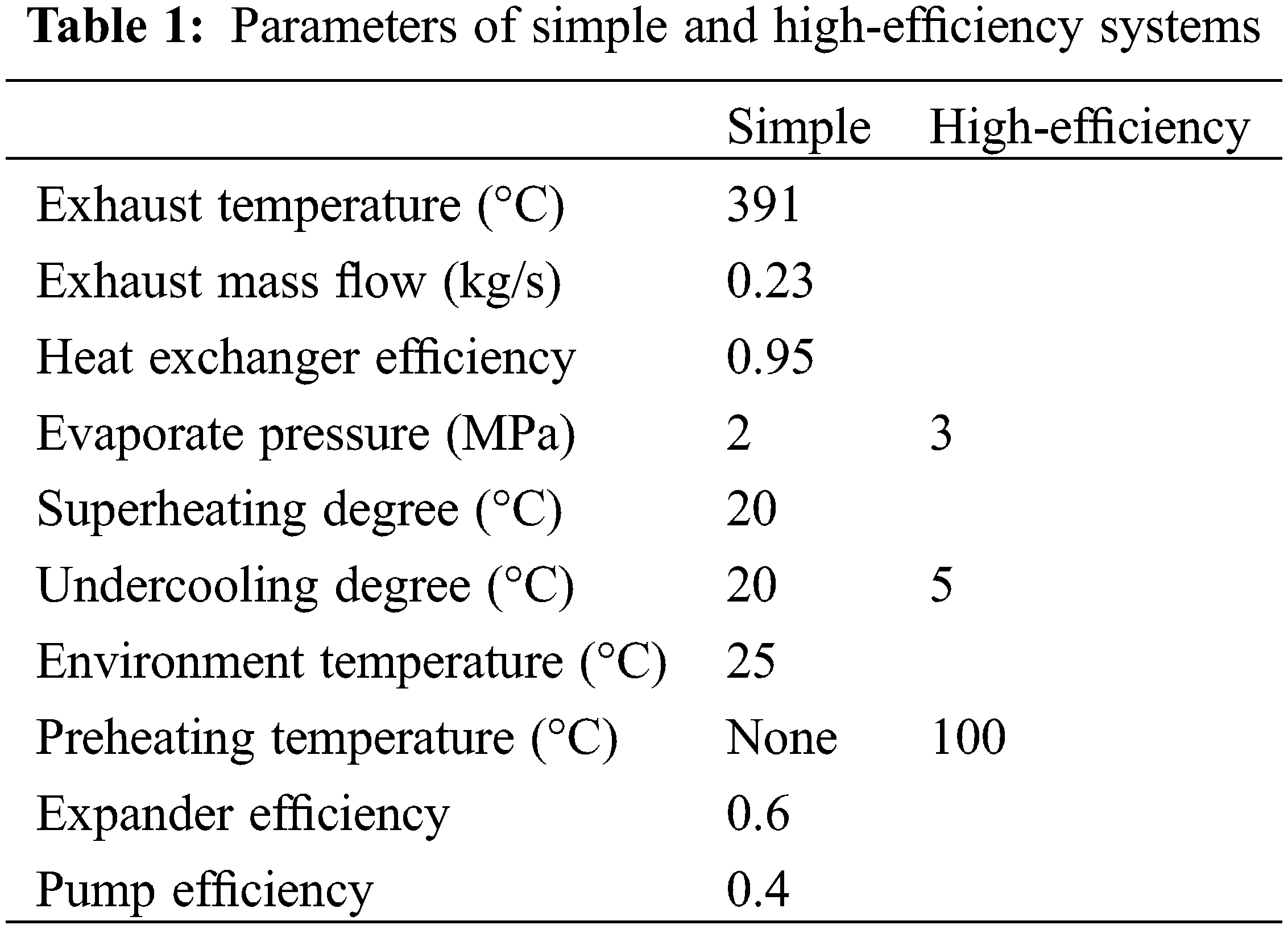
Parameters of the evaporator, namely heat transfer loss, working fluid side pressure drop and narrow temperature difference range, are taken from a heat exchanger bench test [17]. Relevant system parameters are shown in Table 1.
The following assumptions are made for the system:
(1) The operating conditions in the ORC system model are all steady-state, and the heat source inlet temperature and flow rate at each operating point are constant.
(2) The working fluid can be fully expanded in the expander, and the efficiency of the expander and working fluid pump is constant.
(3) The pressure drop and heat transfer loss of the evaporator and other heat exchangers are determined concerning experimental data, and the pressure drop and heat transfer loss of pipelines and other components are ignored.
2.2 Heat Exchanger Simulation and Experiment
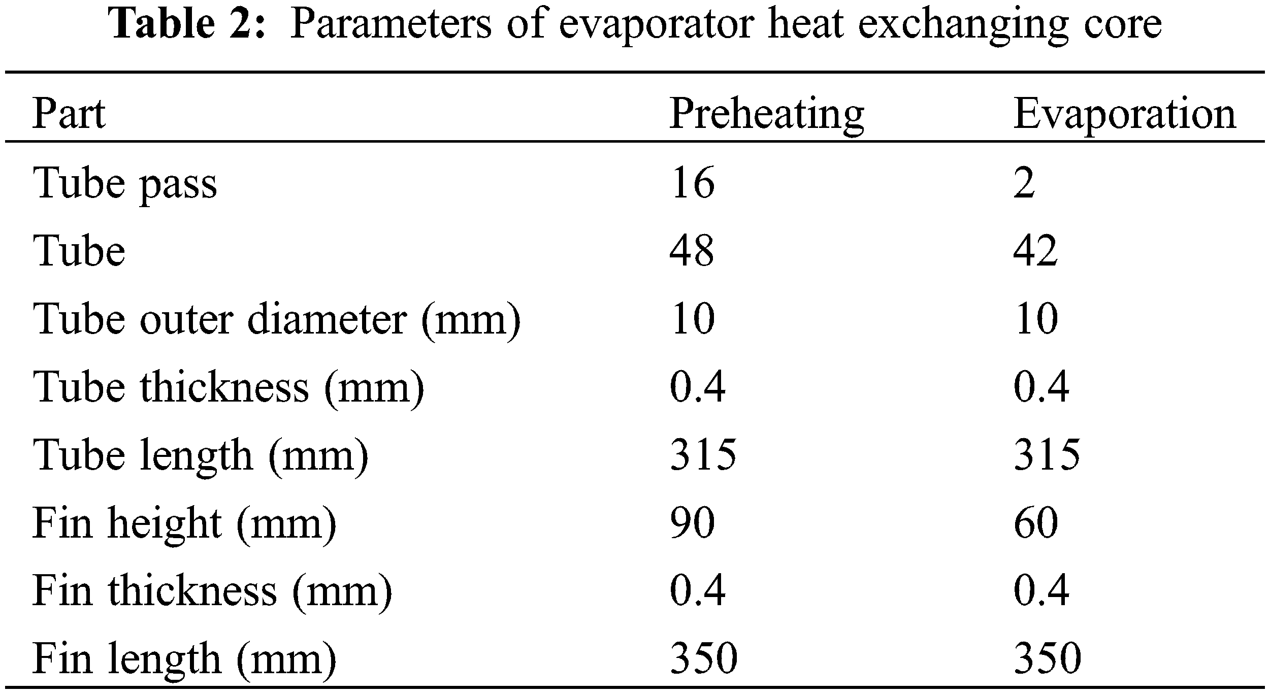
A heat exchanger model is applied for detailed evaporator analysis. To achieve higher working pressure then, a tube-fin heat exchanger is used as the evaporator of the ORC system. The evaporator’s heat exchanging core (HEC) is divided into two parts, the evaporation part and the preheating part.
2.2.1 Basic Heat Exchanger Model
The exhaust side of the tube-fin heat exchanger model is taken from Li et al. [18]:
where s is the distance between fins, s2 is the vertical distance between tubes, d3 is the fin thickness, N is the number of fins.
The single-phase flow within the fluid side is calculated through the renowned Gnielinski equation [19]:
The preheating of the working fluid happens in the preheating part, the superheating of the fluid happens in the evaporation part.
The two-phase zone, or the evaporation of the fluid, is calculated through Eq. (4) [20]:
After the heat transfer coefficient of the heat exchanger calculation, the heat transfer area will be calculated via log-mean temperature difference (LMTD) method:
where K stands for the total heat transfer coefficient, A stands for the equivalent collecting area of the HEC.
The 3D model of the HEC is constructed for CFD simulation. The structure of the tube-fin evaporator is given in Fig. 2. Two different core designs are applied on the preheating part or single-phrase zone (left), and the evaporation part or two-phrase zone (right), and deployed as in Fig. 3, to decrease the pressure loss of the former part and increase the reliability of the latter part. The weight of HEC is determined by the actual number of tubes and fins.
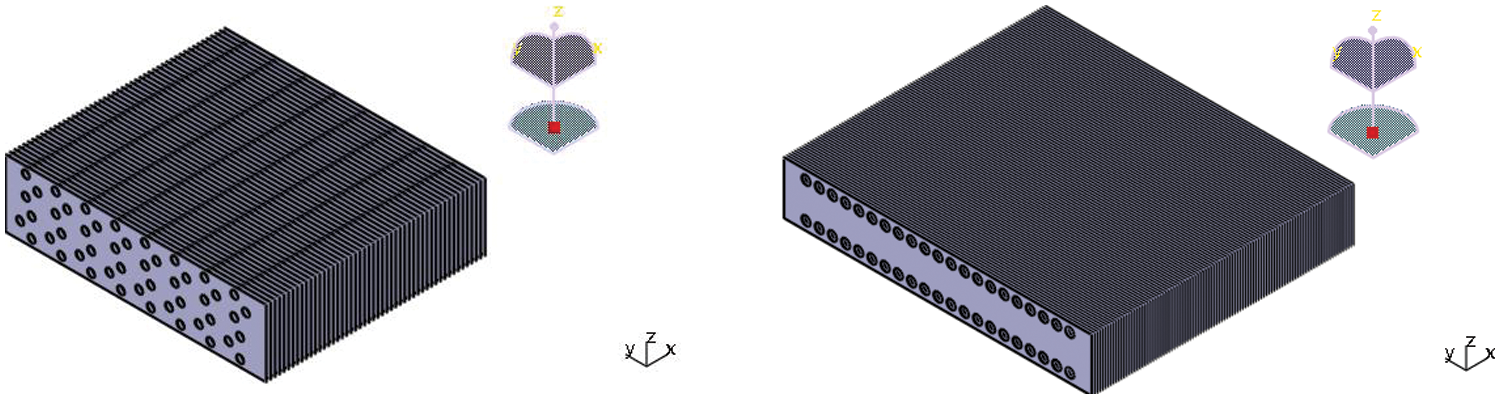
Figure 2: Evaporator HEC structure
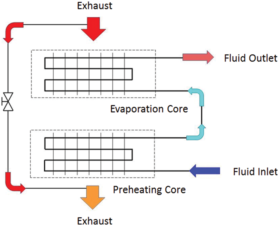
Figure 3: HEC deployment within evaporator
Governing equations of continuity, momentum and energy can be listed as:
where ρ represents the density, u is the velocity, t is the time, P is the pressure, μ is the viscosity, k is the thermal conductivity, T is temperature and S is heat source. Energy generated from dissipation is ignored.
The simulation used the standard k-omega model, for lower Reynolds number situation:
where Gk and Gω represent the generation of k and ω due to mean velocity gradients, Γk and Γω represent the effective diffusivity of k and ω, and Yk and Yω represent the dissipation of k and ω due to turbulence.
The low-Reynolds-number correction is given by a coefficient α:
The turbulent viscosity is modified by this coefficient:
The CFD model is a pressure-based solver with steady-state iterative algorithm, absolute velocity formulation and compressible fluid (exhaust), and simple pressure-velocity coupling. The simulation of compressible fluid model is similar to Giacomelli et al. [21]. As the calculation mainly focused on heat transfer, momentum and energy calculation chose second-order upwind scheme, k and ω chose first-order upwind scheme, while pressure chose standard scheme.
2.2.3 Mesh Sensitivity Analysis
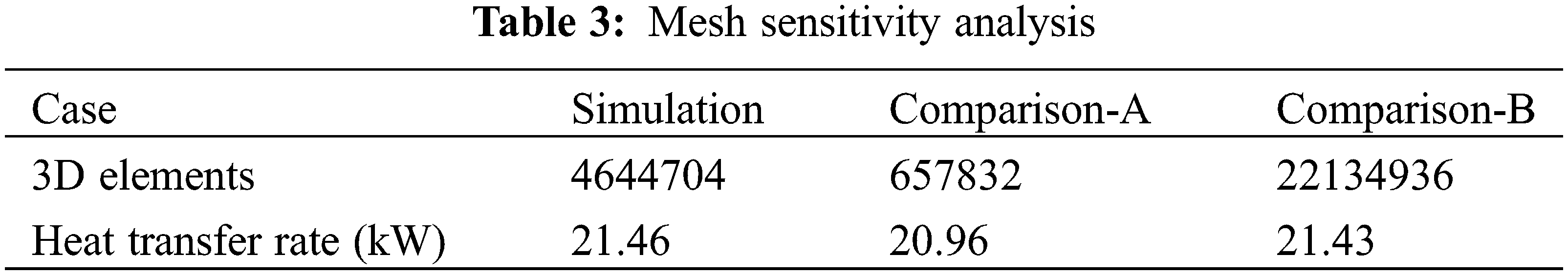
The mesh sensitivity analysis also focused on energy transfer. Two comparison models are meshed in same geometric structure, with element quantity decreased in comparison model A and increased in B. The comparison is given in Table 3. The heat transfer rate at different model varied by a maximum of 2.33%, the mesh sensitivity of this simulation is acceptable.
The main theme of this paper, evaporator simulation model is verified through bench test (Fig. 4). The performance of the test evaporator using similar design and certain working fluid (R245fa) verified the simulation model. The main task of the validation is heat exchanger (evaporator) heat flux at different exhaust temperature. Heated air at different temperature is used as experimental heat source. At different heat source condition, the temperature and pressure of working fluid at the inlet and outlet is taken for comparison. The comparison result is given in Fig. 5, and error of the simulation model is well below 5%.
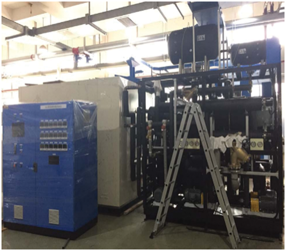
Figure 4: Heat exchanger test bench
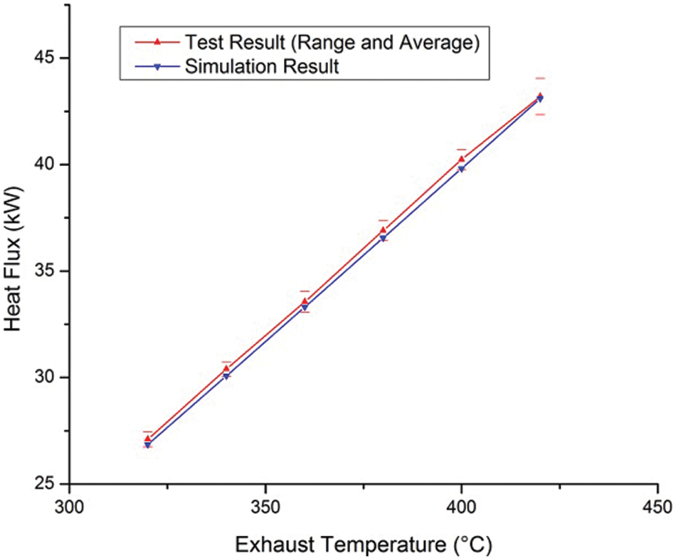
Figure 5: Heat exchanger model validation
The ORC model is partly verified by the experiment, while other parameters are taken from follow references. The condensing temperature range is taken from Shu et al. [5]. The expander and the pump both affect the ORC system output. However, neither has a significant direct effect on the evaporator; as the evaporator is upstream of the expander, the isentropic efficiency of the expander affects the temperature at the expander outlet, yet it has little effect at its inlet. The isentropic efficiency of the expander is taken from Bao et al. [22]. If no other heat exchanger is applied, the isentropic efficiency of the pump affects the inlet of the evaporator directly. However, the pump’s energy consumption is relatively small in the ORC system energy flow, the effect is limited. Pump efficiency is taken from Shu et al. [5]. Although important for the ORC system design, the optimization of these components will not be taken into detailed consideration in this paper.
The evaporation pressure directly affects both the expansion ratio of the expander and the temperature difference within the evaporator. The thermal and exergy efficiency increase through evaporation pressure increase will inevitably cause an increase in both the capital cost and weight of the evaporator, beside other changes. Detailed analysis is given in Figs. 6 and 7. The ethanol ORC system and the R245fa system both benefited from the evaporation pressure increase, while the area and weight of the evaporator HEC also increased accordingly. The exergy efficiency increase of the ethanol system at 3 MPa is 9.15%, while the increase of the R245fa system is 16.88%. The weight increase of the evaporator is less significant, mainly because the evaporation temperature increase is also limited. The weight of the evaporator in the ethanol system increased by 2.06%, while the R245fa system increased by 1.06%.
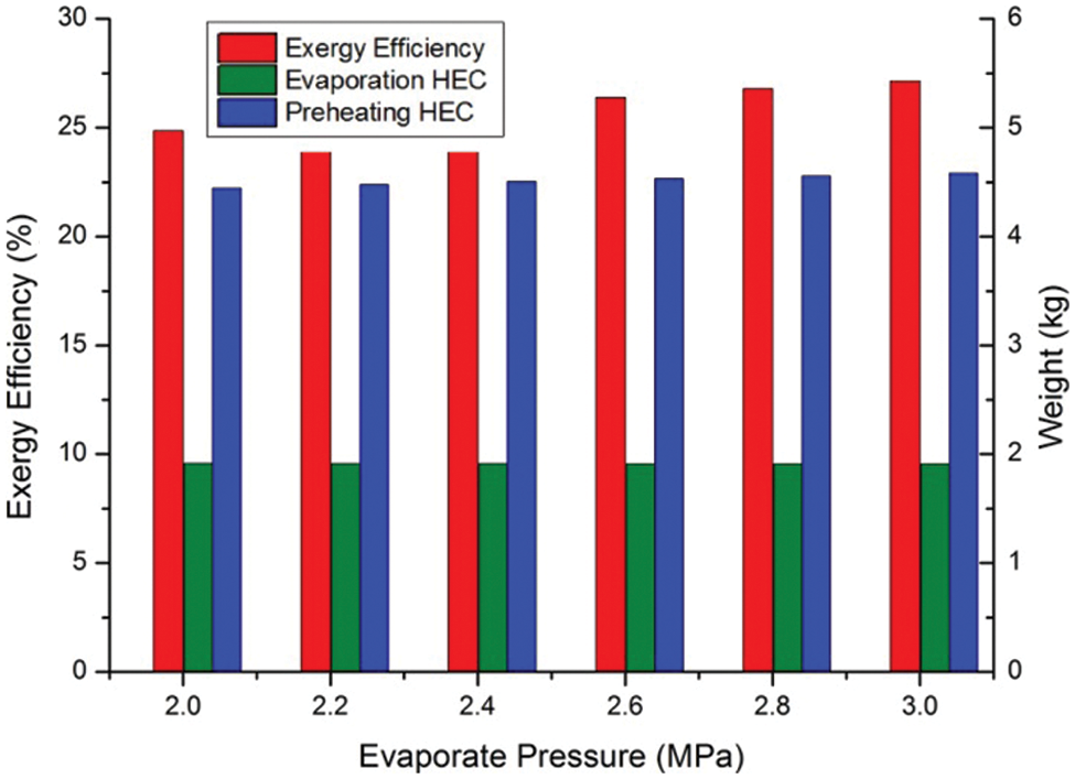
Figure 6: Ethanol ORC system at different evaporate pressure
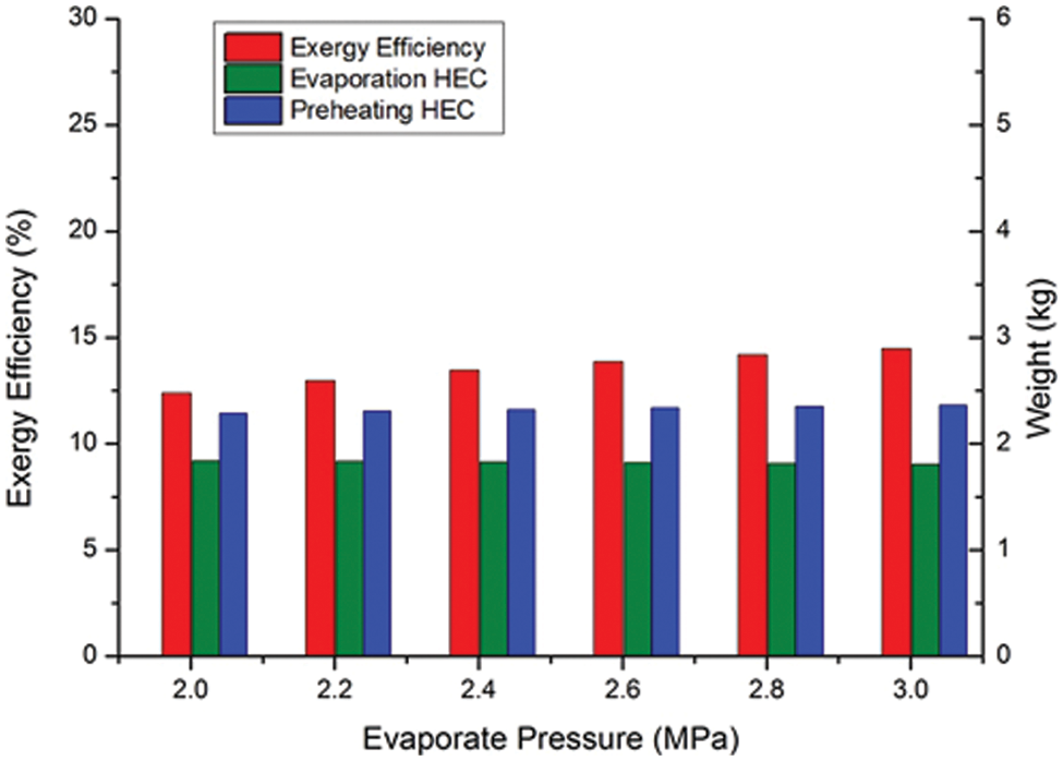
Figure 7: R245fa ORC system at different evaporate pressure
At 3 MPa, the R245fa system required a much lighter preheating HEC, only 48.86% of the ethanol preheating HEC, the weight of the evaporator HEC is 35.73% lighter. However, the exergy efficiency of the R245fa system at 3 MPa is only 53.36% of the 3 MPa ethanol system; the condense pressure of the R245fa system requires further analysis and optimization.
Two parameters of the ORC system are mainly determined by the condenser, the condense temperature and the supercooling degree. The condensing temperature affects the expansion ratio of the expander, thus directly affecting the thermal efficiency of the ORC system. The proper supercooling degree is necessary for reliable system operation, since condenser with larger supercooling degree requires more heat in the preheating process and decreases the thermal efficiency of the ORC system. With the outlet temperature remaining at 30°C, decrease the R245fa ORC system condensing temperature from 60°C to 35°C, the system exergy efficiency increased by 52.96%. Besides, with the condensing temperature remaining at 60°C, decreasing the supercooling degree from 30°C to 5°C also increased the system exergy efficiency by 11.97%.
The condenser also affects the evaporator in terms of working fluid inlet temperature, as shown in Fig. 8. Decrease inlet temperature increases the heat exchanging quantity of the preheating part, yet also increases the temperature difference within the evaporator. Therefore, even with the ORC system exergy efficiency increased by 27.41%, the difference of the evaporator is only 0.023%. The effect of the condenser on the evaporator is comparatively insignificant.
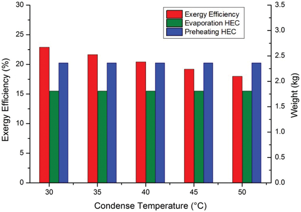
Figure 8: R245fa ORC system at different condense temperature
The condense temperature of ethanol at ambient pressure is 78.09°C, which is comparatively easy to achieve. Further decreasing the condense pressure may cause negative pressure within the ORC system; therefore, the condenser of the ethanol ORC system will not further decrease these two parameters.
The simple ORC system recovers waste heat solely from the exhaust evaporator, yet the low-temperature working fluid can recover waste heat from the engine coolant, charge intercooler and even working fluid steam before condensing. The effect of the ORC system scheme, namely additional preheating heat exchangers, is simulated through inlet temperature change. As the working fluid absorbs waste heat from other sources before entering the evaporator, the fluid inlet temperature of the exhaust evaporator increases accordingly.
As shown in Fig. 9, upstream heat recovery has obvious effect on the inlet temperature. The effect on the ORC system is an increase in system exergy efficiency as more energy is recovered. With inlet temperature increased to 100°C, the exergy efficiency of the ethanol ORC system increased by 12.03%. The effect on the exhaust exchanger is more complex. The preheating process within the evaporator requires proportionally less waste heat. However, the increase in fluid inlet temperature also decreases the temperature difference within the evaporator, which requires an increase in heat exchanging aera, which further increases the weight and the capital cost of the system, besides the increase caused by additional heat exchangers. The cost of the exergy efficiency increase in the ethanol ORC system is an increase of 9.71% in mere evaporator weight, which inevitably increase the capital cost. The high condense temperature of ethanol is a major disadvantage in low-quality heat recovery, as little temperature difference remains for recovery.
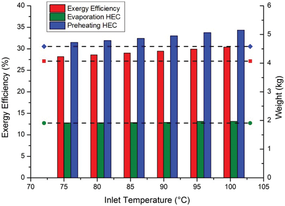
Figure 9: Ethanol ORC system at different fluid inlet temperature
For the R245fa system, the effect of the complex system scheme is more significant and positive. In the ethanol system, the enthalpy of evaporation is 50.34% of the total enthalpy increase within the evaporator, while the R245fa system is only 31.94%. A much larger proportion of waste heat is recovered in the preheating process. Besides, the low condense temperature retained a large temperature difference for low-quality heat recovery. The larger temperature difference within the evaporator is less affected by the inlet temperature increase. In contrast, the larger proportion of heat in the preheating process further increases the system exergy efficiency. As shown in Fig. 10, with inlet temperature also increased to 100°C, the exergy efficiency of the R245fa ORC system increased by 39.58%. The weight and the capital cost increase in the evaporator remain. However, the considerable decrease in heat exchanging quantity of the preheating part compensated for the reduction in temperature difference. The 5.14% increase at 100°C inlet temperature is less significant than in the ethanol ORC system.
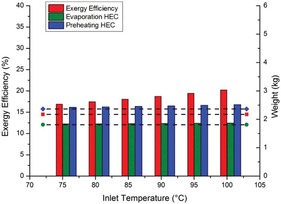
Figure 10: R245fa ORC system at different fluid inlet temperature
3.4 Comprehensive Optimization
The comparison of the five working fluids in Li et al. [17] mainly focused on the ORC system performance at different heat source temperature, yet a detailed analysis of the optimization in evaporating pressure, condense temperature and additional preheating heat source, remained to be supplemented. The system exergy efficiency of the ORC system increases with different optimization, namely, increasing the evaporate pressure from 2 to 3 MPa, decreasing condense temperature to 35°C (only when the condense pressure remained above the ambient pressure) and the supercooling degree to 5°C, and imply additional preheating heat source to increase the working fluid inlet temperature of the evaporator to 100°C.
The optimization result of the five systems is given in Fig. 11. For working fluids with both low evaporate and condense temperature, all optimization methods applied have significant effect on the system exergy efficiency. The optimal R245fa system has the most significant efficiency increase of 177.49% with all three methods combined. With the same system parameter, the output of the R1233zd system is still better than the R245fa system, yet the maximum efficiency increase of the R1233zd system is slightly less at 146.74%. The efficiency of the R245fa system after all optimization combined is 95.25% of the R1233zd system with the same parameter, which is a considerable increase compared to the 84.69% before optimization. For working fluids with both high evaporate and condense temperature, the efficiency increase through the optimization is less significant. Ethanol has the highest efficiency among simple systems before optimization, yet benefits from optimization methods are limited. The exergy efficiency of the optimal cyclopentane system increased by 54.48% compared to the simple scheme. Meanwhile, the ethanol system’s increase and the cyclohexane system’s increase are only 22.09% and 17.29%, respectively. Still, the cyclopentane system has the best exergy efficiency of the five, though the final efficiency of 37.28% is only 3.19% better than the R1233zd system.
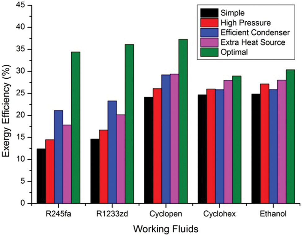
Figure 11: ORC system efficiency with different optimization methods
As shown in Fig. 12, the two fluids with low evaporation temperature have a significant advantage in terms of the evaporator. The evaporator HEC weight of the optimized R1233zd system is only 68.96% of the cyclopentane system, and the 3.19% efficiency advantage of the cyclopentane system is much less significant. Even the high-efficiency of the simple ethanol system is less acceptable if the weight and cost of the evaporator are emphasized. It needs to be mentioned that the high-efficiency of the optimized R1233zd ORC system is achieved by decreasing the condense temperature to 35°C, which requires additional attention in system cooling.
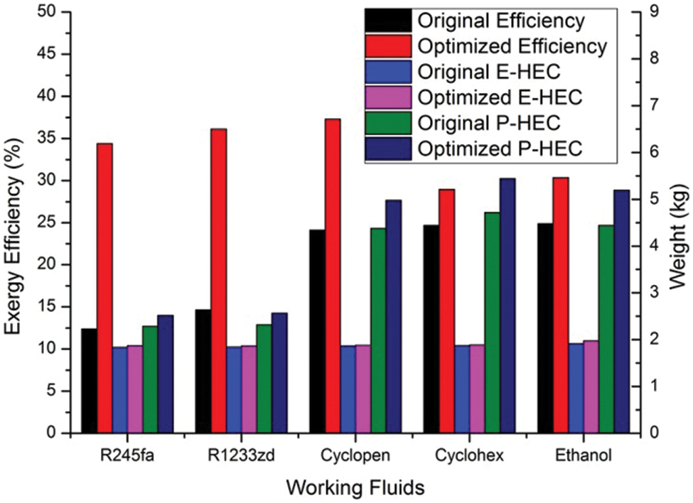
Figure 12: Effect of optimization methods on ORC evaporators
The analysis of this paper focused on the evaporator of the ORC system, to achieve high-efficiency waste heat recovery from heavy-duty diesel engines. Several optimization methods coupled with different types of working fluids are compared in terms of exergy efficiency and heat exchanger weight and cost.
(1) At the same evaporate pressure, the HEC weight is determined by the evaporating temperature of working fluids, fluids with high evaporate temperature requires a larger evaporator, and optimization methods also causes a significant HEC weight increase. The weight of ethanol evaporator HEC increased by 12.76% in the optimal system, and the final HEC weight is 163.51% of the R245fa evaporator at the same system parameter.
(2) Effect of evaporate pressure and condense temperature have significant effect on ORC system efficiency and power output, ranges from 9%–17%, while the increase in HEC weight is below 3% in all cases, insignificant in terms of total system cost and weight increase. Reliability and availability is the major concern of the two parameters.
(3) Add an extra heat source, either through preheating or recuperating, inevitably requires extra equipments and has significant effect in system complicity. Beside other requirements, the increase of inlet temperature will significantly increase the HEC of evaporator, especially for the preheating HEC of fluids with high condense temperature. The 12.03% output increase of ethanol system is achieved at the cost of increase evaporator HEC by 9.71%.
(4) The ethanol system has the highest efficiency among the simple ORC systems. The cyclopentane system has the highest efficiency among the optimal ORC systems. The optimal R245fa system has the highest efficiency increase of the five, while the optimal R1233zd system achieved 96.84% efficiency of the cyclopentane system with only 68.96% evaporator HEC weight.
Acknowledgement: I personally appreciate the editors and reviewers for their constructive and detailed critiques contributed to the quality of this paper.
Funding Statement: This work was funded by National Engineering Laboratory for Mobile Source Emission Control Technology of China [Grant No. NELMS2019A01], and the Undergraduate School of Shandong University, China [Grant No. 2022Y155].
Conflicts of Interest: The authors declare that they have no conflicts of interest to report regarding the present study.
References
1. Lin, B., Benjamin, N. I. (2017). Influencing factors on carbon emissions in China transport industry. A new evidence from quantile regression analysis. Journal of Cleaner Production, 150(5), 175–187. DOI 10.1016/j.jclepro.2017.02.171. [Google Scholar] [CrossRef]
2. Holik, M., Živić, M., Virag, Z., Barac, A. (2019). Optimization of an organic Rankine cycle constrained by the application of compact heat exchangers. Energy Conversion and Management, 188, 333–345. DOI 10.1016/j.enconman.2019.03.039. [Google Scholar] [CrossRef]
3. Liu, H., Zhang, H., Yang, F., Hou, X., Yu, F. et al. (2017). Multi-objective optimization of fin and tube evaporator for a diesel engine-organic Rankine cycle (ORC) combined system using particle swarm optimization algorithm. Energy Conversion and Management, 151, 147–157. DOI 10.1016/j.enconman.2017.08.081. [Google Scholar] [CrossRef]
4. Mastrullo, R., Mauro, A., Revellin, R., Viscito, L. (2015). Modeling and optimization of a shell and louvered fin mini-tubes heat exchanger in an ORC powered by an internal combustion engine. Energy Conversion and Management, 101, 697–712. DOI 10.1016/j.enconman.2015.06.012. [Google Scholar] [CrossRef]
5. Shu, G., Yu, G., Tian, H., Wei, H., Liang, X. et al. (2016). Multi-approach evaluations of a cascade-Organic Rankine Cycle (C-ORC) system driven by diesel engine waste heat: Part A–Thermodynamic evaluations. Energy Conversion and Management, 108, 579–595. DOI 10.1016/j.enconman.2015.10.084. [Google Scholar] [CrossRef]
6. Shu, G., Yu, G., Tian, H., Wei, H., Liang, X. et al. (2016). Multi-approach evaluations of a cascade-Organic Rankine Cycle (C-ORC) system driven by diesel engine waste heat: Part B–techno-economic evaluations. Energy Conversion and Management, 108, 596–608. DOI 10.1016/j.enconman.2015.10.085. [Google Scholar] [CrossRef]
7. Mavridou, S., Mavropoulos, G., Bouris, D., Hountalas, D., Bergeles, G. (2010). Comparative design study of a diesel exhaust gas heat exchanger for truck applications with conventional and state of the art heat transfer enhancements. Applied Thermal Engineering, 30(8–9), 935–947. DOI 10.1016/j.applthermaleng.2010.01.003. [Google Scholar] [CrossRef]
8. Preißinger, M., Schwöbel, J., Klamt, A., Brüggemann, D. (2017). Multi-criteria evaluation of several million working fluids for waste heat recovery by means of organic rankine cycle in passenger cars and heavy-duty trucks. Applied Energy, 206(2), 887–899. DOI 10.1016/j.apenergy.2017.08.212. [Google Scholar] [CrossRef]
9. Chen, T., Zhuge, W., Zhang, Y., Zhang, L. (2017). A novel cascade organic rankine cycle (ORC) system for waste heat recovery of truck diesel engines. Energy Conversion and Management, 138(9), 210–223. DOI 10.1016/j.enconman.2017.01.056. [Google Scholar] [CrossRef]
10. Zhu, Y., Li, W., Sun, G., Li, H. (2018). Thermo-economic analysis based on objective functions of an organic rankine cycle for waste heat recovery from marine diesel engine. Energy, 158(5), 343–356. DOI 10.1016/j.energy.2018.06.047. [Google Scholar] [CrossRef]
11. Talluri, L., Dumont, O., Manfrida, G., Lemort, V., Fiaschi, D. (2020). Experimental investigation of an organic rankine cycle tesla turbine working with R1233zd(E). Applied Thermal Engineering, 174(1), 115293. DOI 10.1016/j.applthermaleng.2020.115293. [Google Scholar] [CrossRef]
12. Yang, J., Ye, Z., Yu, B., Ouyang, H., Chen, J. (2019). Simultaneous experimental comparison of low-GWP refrigerants as drop-in replacements to R245fa for organic rankine cycle application: R1234ze(ZR1233zd(Eand R1336mzz(E). Energy, 173(1), 721–731. DOI 10.1016/j.energy.2019.02.054. [Google Scholar] [CrossRef]
13. Li, X., Tian, H., Shu, G., Zhao, M., Markides, C. et al. (2019). Potential of carbon dioxide transcritical power cycle waste-heat recovery systems for heavy-duty truck engines. Applied Energy, 250(1), 1581–1599. DOI 10.1016/j.apenergy.2019.05.082. [Google Scholar] [CrossRef]
14. Lu, Y., Roskilly, A., Yu, X., Tang, K., Jiang, L. et al. (2017). Parametric study for small scale engine coolant and exhaust heat recovery system using different organic rankine cycle layouts. Applied Thermal Engineering, 127(1), 1252–1266. DOI 10.1016/j.applthermaleng.2017.08.128. [Google Scholar] [CrossRef]
15. Freymann, R., Ringler, J., Seifert, M., Horst, T. (2012). The second generation turbosteamer. MTZ Worldwide, 73(2), 18–23. DOI 10.1365/s38313-012-0138-1. [Google Scholar] [CrossRef]
16. Amicabile, S., Lee, J., Kum, D. (2015). A comprehensive design methodology of organic rankine cycles for the waste heat recovery of automotive heavy-duty diesel engines. Applied Thermal Engineering, 87, 574–585. DOI 10.1016/j.applthermaleng.2015.04.034. [Google Scholar] [CrossRef]
17. Li, D., Sun, Q., Sun, K., Zhang, G., Bai, S. et al. (2021). Diesel engine waste heat recovery system comprehensive optimization based on system and heat exchanger simulation. Open Physics, 19(1), 331–340. DOI 10.1515/phys-2021-0039. [Google Scholar] [CrossRef]
18. Li, W., Tao, W., Kang, H., Li, H., Xin, R. (1997). Experimental study on heat transfer and pressure drop characteristics for fin-and-tube heat exchangers. Chinese Journal of Mechanical Engineering, 33(1), 81–86. DOI 10.1186/s10033-020-00500-z. [Google Scholar] [CrossRef]
19. Kew, P., Cornwell, K. (1997). Correlations for the prediction of boiling heat transfer in small-diameter channels. Applied Thermal Engineering, 17(8–10), 705–715. DOI 10.1016/S1359-4311(96)00071-3. [Google Scholar] [CrossRef]
20. Kandylas, I., Stamatelos, A. (1999). Engine exhaust system design based on heat transfer computation. Energy Conversion and Management, 40(10), 1057–1072. DOI 10.1016/S0196-8904(99)00008-4. [Google Scholar] [CrossRef]
21. Giacomelli, F., Mazzelli, F., Milazzo, A. (2018). A novel CFD approach for the computation of R744 flashing nozzles in compressible and metastable conditions. Energy, 162(1), 1092–1105. DOI 10.1016/j.energy.2018.08.050. [Google Scholar] [CrossRef]
22. Bao, J., Zhao, L. (2013). A review of working fluid and expander selections for organic rankine cycle. Renewable and Sustainable Energy Reviews, 24(8), 325–342. DOI 10.1016/j.rser.2013.03.040. [Google Scholar] [CrossRef]
Cite This Article
 Copyright © 2023 The Author(s). Published by Tech Science Press.
This work is licensed under a Creative Commons Attribution 4.0 International License , which permits unrestricted use, distribution, and reproduction in any medium, provided the original work is properly cited.
 Downloads
 Citation Tools