
 Submit a Paper
 Propose a Special lssue
 Open Access
ARTICLE

Durability Testing of Composite Aerospace Materials Based on a New Polymer Carbon Fiber-Reinforced Epoxy Resin
School of Mechanical and Electrical Engineering, Sanya Aviation & Tourism College, Sanya, 572000, China
* Corresponding Author: Jinlong Shang. Email:
(This article belongs to the Special Issue: Advanced Materials, Processing and Testing Technology)
Fluid Dynamics & Materials Processing 2023, 19(9), 2315-2328. https://doi.org/10.32604/fdmp.2023.026742
Received 31 May 2022; Accepted 13 September 2022; Issue published 16 May 2023
 View Full Text
 Download PDF
Abstract
In this study, the durability of a new polymer carbon fiber-reinforced epoxy resin used to produce composite material in the aerospace field is investigated through analysis of the corrosion phenomena occurring at the microscopic scale, and the related infrared spectra and thermal properties. It is found that light and heat can contribute to the aging process. In particular, the longitudinal tensile strength displays a non-monotonic trend, i.e., it first increases and then decreases over time. By contrast, the longitudinal compressive and inter-laminar shear strengths do not show significant changes. It is also shown that the inter-laminar shear strength of carbon fiber/epoxy resin composites with inter-laminar hybrid structure is better than that of pure carbon fiber materials. The related resistance to corrosion can be improved by more than 41%.Keywords
Carbon fiber reinforced epoxy resin composites have excellent mechanical properties and play an increasingly important role in the aerospace industry. These composite materials have very high mechanical properties, such as specific strength and modulus, so they are widely used in Production of some structural and load-bearing parts in aerospace. Compared with metals and other materials, carbon fiber composite materials have many factors that affect the material’s mechanical properties due to the more complex manufacturing process. By adding fine particles, the combination of carbon fiber and matrix can be increased, thereby increasing composite materials’ tensile strength and fracture toughness [1]. Due to the existence of these factors, the factors affecting the mechanical properties of carbon fiber reinforced composites in this paper, the factors affecting the mechanical properties of carbon fiber reinforced epoxy resin composites are analyzed and summarized from three aspects: the composition and structure of composite materials, the preparation process of composite materials, and the wet and hot service environment of composite materials. In this paper, typical carbon fiber reinforced epoxy resin matrix composites are selected to study the surface microscopic morphology, surface element content, thermal properties, and mechanical properties of the composite materials after natural corrosion to discuss the effect of tropical oceanic climate on carbon fiber reinforced rings. The effect of oxy-resin matrix composites on durability.
The raw materials used are prepreg epoxy resin-A (NO. A), prepreg epoxy resin-B (NO. B), and carbon fiber.
The carbon fiber reinforced epoxy resin-based (NO. A) composite material resin matrix adopts a hybrid resin system of bisphenol A glycidyl ether type epoxy resin and 4,4-diaminodiphenylmethane tetra glycidyl amine, and the curing agent adopts 4, 4’-Diaminodiphenylsulfone (DDS). The epoxy resin and curing agent are shown in Fig. 1. During the curing reaction of epoxy resin, the primary amine group in the DDS molecule will undergo a ring-opening addition reaction with epoxy groups to form secondary amines, which will further react with other epoxy groups to form tertiary amines, and finally form a cross-linked structure. Due to steric hindrance, all epoxy groups cannot react entirely with the curing agent molecules. Therefore, the ideal chemical structure of the carbon fiber reinforced epoxy resin matrix (NO. A) composite resin system after complete curing should be shown in Fig. 2. At the same time, the resin system also contains a certain amount of thermoplastic toughening agent polyether sulfone (PES), whose molecular formula is shown in Fig. 3 [2].
Figure 1: Epoxy resin and hardener
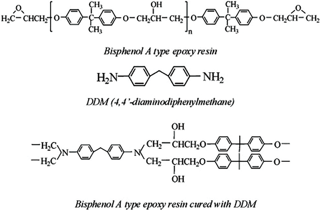
Figure 2: Ideal chemical structure of carbon fiber reinforced epoxy resin matrix (NO. A) composite resin system
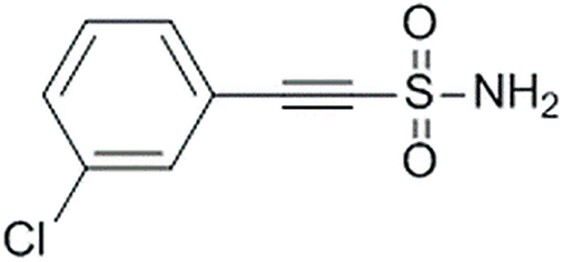
Figure 3: Molecular formula of toughening agent PES
2.2 Preparation of Composite Materials
In this paper, carbon fiber reinforced epoxy resin based (NO. A) composite unidirectional prepreg and carbon fiber reinforced epoxy resin based (NO. B) unidirectional prepreg was prepared by wet prepreg process. In the experiment, the carbon fiber reinforced epoxy resin-based (NO. A) composite material prepreg was laid and packaged in a vacuum bag. The carbon fiber reinforced epoxy resin based (NO. A) the autoclave molding process formed composite material unidirectional layer. The curing process is vacuuming at room temperature, and the degree of vacuum is not less than 0.095 MPa. Heat up to (120 ± 5)°C at a heating rate of 0.5–2.0 °C/min, pressurize 0.6 MPa and hold for 30 min. The samples were naturally cooled to below 60°C and out of the tank. This paper used the same method to prepare carbon fiber reinforced epoxy resin matrix (NO. B) composite unidirectional laminates.
2.3 Natural Corrosion of Composite Materials
The natural corrosion site of composite materials is a natural environment test station, and the samples are exposed in a stress-free state. The exposure angle is 45°. The side of the sample exposed to natural light is the light-facing side, and the side that does not receive natural light exposure is the backlit side [3]. The aging time is three years and five years, respectively. The annual average temperature of the natural experimental station is 24.6°C, the annual average relative humidity is 86%, the annual precipitation is 1942 mm, the annual sunshine hours is 2154 h, and the annual total radiation is 4826 MJ/m2. This area belongs to a typical high-temperature and high-humidity marine atmospheric environment.
2.4 Characteristic Color of Material Corrosion and HSV Color Space
In material corrosion characteristic color analysis, color is an essential descriptor of material corrosion grade. Selecting a suitable color expression is crucial in material corrosion characteristic color processing. At the same time, the description of color characteristics depends on the color space used. Not all color spaces are consistent with human vision. Color space can be roughly divided into RGB, CMY, CIE, HSV, and so on. Due to the relationship of hardware technology, the RGB color space is mainly used to obtain the original image information of material corrosion characteristics. Due to the close relationship between color and human vision, HSV color space corresponds to the painter’s color matching model, which can better reflect people’s ability to perceive and discriminate color, that is, the way human visual senses understand color [4]. In addition, the Euclidean distance of different colors in HSV space is roughly the same as the visual sensory distance. It has a reasonable degree of discrimination, so it is an effective way to use HSV space to process the characteristic color of material corrosion. For the HSV color space, it uses the separation of chroma (H), saturation (S), and brightness (V) to achieve a quantitative description of color. H represents the color information. Tthe position of the spectral color is in the range of 0° to 360°. The value of S ranges from 0.0 to 1.0. When S = 0, there is only a grayscale. The larger the value, the more saturated the color. V represents the brightness of the color, ranging from 0.0 (black) to 1.0 (white), which is not directly related to the light intensity. In the color processing in the HSV space, the three components H, S, and V all have clear semantic correspondence, in which the luminance component V and the chrominance H are separated. Considering that the original image information of material corrosion characteristics is in RGB format, it is necessary to convert the color of RGB space to HSV space. After the above transformation,
The basic information for grading the corrosion feature of the material appearance is the primary color value of the corrosion feature area [5]. The area of the corroded region that closes the corroded region pixel is represented by
Among them,
In the color block of the corrosion feature area, due to the uneven color distribution of the material corrosion feature area, it is affected by the different degrees of corrosion, resulting in some pixels with sensitive points [6]. The influence of extreme values (significant or minimal) in the data will result in the primary color processing bias.
(1) When the hue H changes from 0° to 360°, the hues appear in sequence as red, orange, yellow, green, cyan, blue, and purple. In line with human vision’s psychological perception of color, the quantification of H is divided into different degrees. Sixteen parts of the interval, the saturation S space, and the brightness V space are unequally divided into three parts. When h falls in [0, 15] or [345, 360], then H is quantized to 0. When h falls in [15, 25), [25, 45), [45, 55), [55, 80), [80, 108), [108, 140), [140, 165), [165, 190), [190, 220), [220, 255), [255, 275), [275, 290), [290, 316), [316, 330), [330, 345) are then quantified as 1, 2, 3..., 15.
(2) Construct a one-dimensional feature vector
The value range of the one-dimensional feature vector
3.1 The Effect of Natural Corrosion on the Surface Microstructure
Fig. 4 shows the surface micro-morphologies of carbon fiber reinforced epoxy resin matrix (NO. A). It can be seen from Fig. 4a that the surface texture of the unaged carbon fiber reinforced epoxy resin matrix (NO. A) composite sample is the resin imprint left by the release cloth during the molding process. The resin matrix covers the fibers, and no exposed surface is found. Fiber. After three years of natural corrosion, most of the surface resin on the light-facing surface of the carbon fiber reinforced epoxy resin matrix (NO. A) composite shown in Fig. 4b was degraded, and the exposed carbon fibers were visible, but the fiber surface remained. There is still some resin adhesion between fibers with a small amount of resin. The fibers were exposed, but compared with the light-facing surface, the Incompletely degraded resin particles are still regularly distributed on the backlight surface of the aged samples, which indicates that the degradation degree of the carbon fiber reinforced epoxy resin-based (NO. A) composite material is higher than that of the backlight surface. After five years of natural corrosion, the light-facing side of the carbon fiber reinforced epoxy resin matrix (NO. A) composite shown in Fig. 4d is the same as the carbon fiber reinforced epoxy resin matrix (NO. A) shown in Fig. 4e. The surface resin on the backlit surface of the composite material is almost completely degraded, the surface of the carbon fiber is smooth without resin residue, and there is no resin adhesion between fibers [7]. It can be confirmed that the surface resin matrix of carbon fiber reinforced epoxy resin matrix (NO. A) composite material both on the light side and the back side is degraded to varying degrees, and the degradation degree of the front side is higher than that of the back side, and with the natural corrosion time. The degradation of the surface resin continued to increase, but the carbon fiber did not show apparent aging damage.
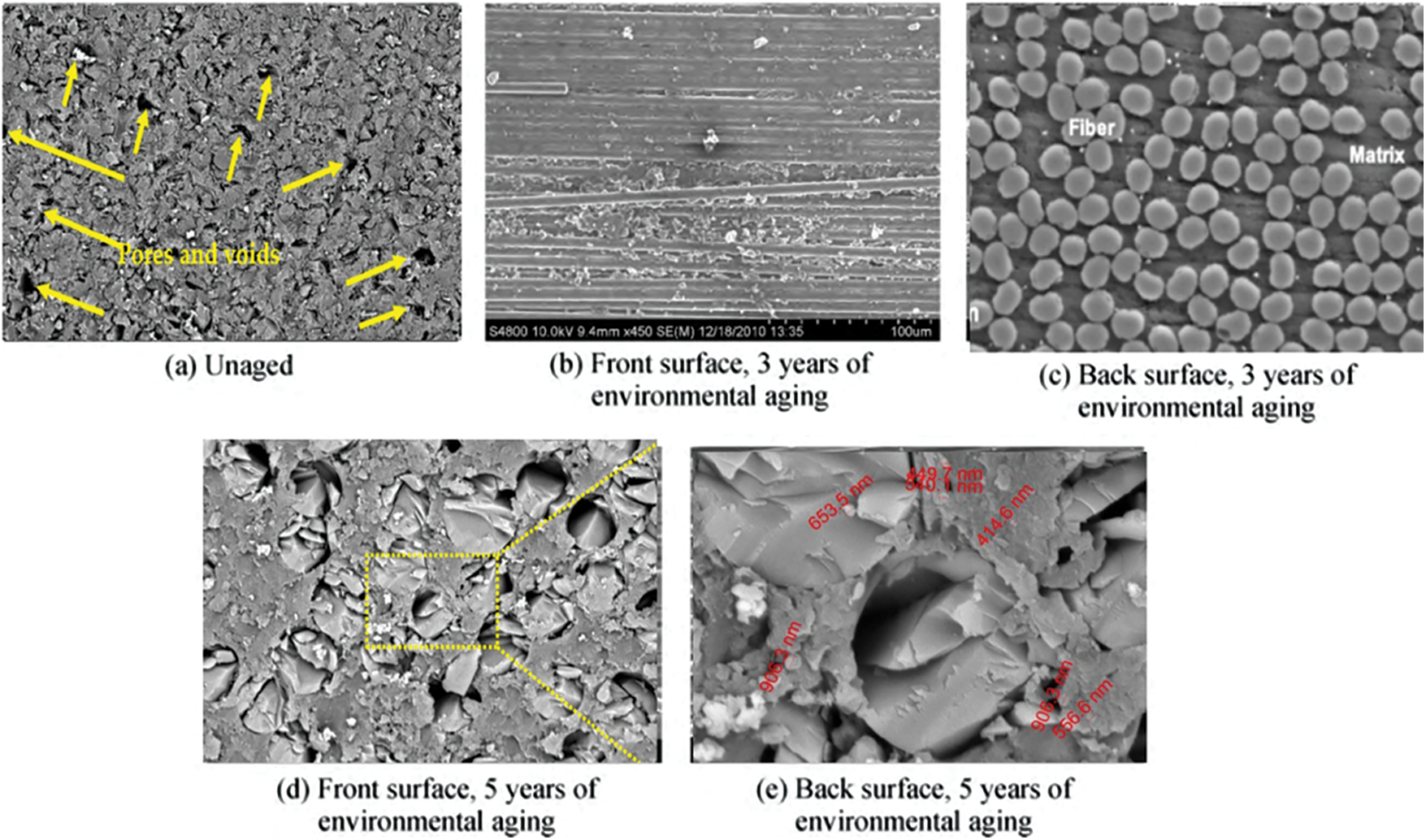
Figure 4: Surface micromorphology of carbon fiber reinforced epoxy resin matrix (NO. A) composite sample (a) The location of holes in the yellow alphabet material (b) is in front of the fiber structure (c) The white letters are fiber structure (d) The yellow line represents the fiber structure after 5 years (e) Red letters indicate NO. The back structure of A is convex (Fig. 4e shows the length of 500–900 nm, randomly selected distance as reference)
3.2 Influence of Natural Corrosion on Surface Element Content and Aging Mechanism
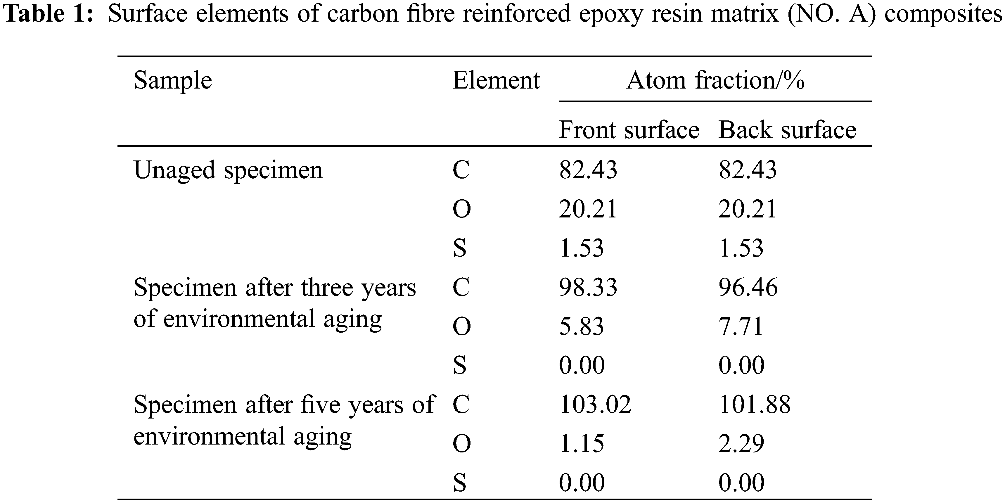
In this paper, a semi-quantitative analysis of surface elements of carbon fiber reinforced epoxy resin matrix (NO. A) composite samples before and after aging was carried out by EDS. Carbon fiber reinforced epoxy resin matrix (NO. A) composite resin matrix mainly contains C, O, S, N, and H elements. Carbon fiber mainly contains two elements, C and N, among which the content of the C element accounts for 95.6%, and the content of the N element accounts for 4.24%. The carbon fiber reinforced epoxy resin-based (NO. A) composite material system mainly contains elements such as C, O, S, N, and H. EDS cannot detect the H atom due to its low atomic number. Due to the low resolution of the EDS attached to the SEM equipment, the element numbers of the C element and the N element are adjacent to each other, which causes the C element energy spectrum signal to mask the N element energy spectrum signal, and the N element cannot be detected [8]. Therefore, the surface of the composite sample was detected by EDS, and three elements, C, O, and S, were mainly detected. In the carbon fiber reinforced epoxy resin matrix (NO. A) hybrid system, the C element exists in both resin and carbon fiber. The two elements O and S mainly exist in the resin matrix. Therefore, C, O, and S elements are selected. As probe atoms, we can study the changes in the surface chemical structure of the composite material after aging. We can judge the loss degree of the surface resin by the abundance of O and S elements. Table 1 shows the surface elements of carbon fiber reinforced epoxy resin matrix (NO. A) composites [9].
According to the above analysis of the surface microstructure and surface elements of the aging samples, it can be seen that the surface resin has undergone severe aging degradation. The aging environment can be used to explain the aging degradation of composite materials. Cafibrefiber reinforced resin matrix composite laminates are exposed to natural light, mainly in contact with oxygen-rich air. In such an environment, ultraviolet rays in natural light will stimulate the molecular segments of the surface resin to generate active free radicals, which react with oxygen in the air. Photooxidative aging degradation occurs. At the same time, the resin matrix of the surface layer also absorbs visible light and infrared light in natural light, converts it into heat at the absorption part to increase the temperature there, and then reacts with oxygen in the airhermosuse thermo-oxidative aging degradation.
Complex physical and chemical reaction processes cause photooxidative aging degradation. Tfibrerbon fiber reinforced epoxy resin matrix (NO. A) composites are exposed to sunlight, and the matrix absorbs ultraviolet rays. Ballenger and Ver-du studied the mechanism of photooxidative aging of polymer materials, and the possible photooxidative aging mechanism is shown in Fig. 5. According to the Einstein photochemical equivalence rule, the photooxidative aging behavior of polymers mainly depends on the energy of a single photon absorbed by the polymer material and the chemical bond energy of the polymer material [10]. The matrix material will be triggered the photon’s energy is greater than or equal to the chemical bond energy. Chain scission occurs when the molecular electron orbital of the matrix material is in an excited state and reacts with reactive oxygen species in the atmosphere to generate reactive radicals and initiate a series of chain transfer reactions. The final reactive free radicals may also combine to form small molecular species and be lost. When the single photon energy absorbedfibrehe carbon fiber reinforced epoxy resin-based (NO. A) composite resin system is greater than or equal to the chemical bond energy, the matrix material will also undergo chain scission or generate free radicals, and the free radicals will further interact with oxygen in the air. The reaction triggers the photooxidative aging reaction, resulting in the degradation and loss of the resin matrix of the surface layer of the light-facing surface as shown in Fig. 5.
Figure 5: Photooxidative aging mechanism of polymer materials
Thermo-oxidative aging degradation means that the surface of the composite material absorbs visible light and infrared light in natural light and converts it into heat at the absorption site to increase the temperature there, thereby promoting the oxidative degradation reaction of the resin matrix. Some schola 8 hermose studied the thermo-oxidative aging mechanism of epoxy resin. 8 hermose 6 shows the thermo-oxidative aging mechanism of epoxy resin. The N atom in the three-dimensional network of epoxy resin is easily oxidized to amine oxide by oxygen molecules. Amine oxide will undergo a Cope elimination reaction at high temperatures to generate hydroxylamine and enol. At this time, the three-dimensional network structure of the epoxy resin has been broken. Enols will further rearrange to form ketones. Hydroxylamine may undergo further dehydration and oxidation reactions to form nitrones, which are rearranged by oxazolidine to form an amide structure [11]. Hydroxylamine may also be dehydrated to form aldimines, which may be further oxidized to form nitrones, and may also be hydrolyzed to form aldehydes and primary amines. Amine oxide and Cope elimination reaction occur at high temperature, resulting in chain scission, and gradualhermosording to the thermo-oxidative aging mechanism shown in Fig. 6.

Figure 6: Thermo-oxidative aging mechanism of epoxy resin
The molecular segments of the resin on the surface of the light-facing surface will be excited by ultraviolet rays in natural light to generate active free radicals and react with oxygen in the air to undergo photooxidative aging degradation. At the same time, the resin matrix of the light-facing surface also absorbs visible light and infrared light in natural light, converts it into heat at the absorption part increase the place’s temperature, and reacts with oxygen molecules 9 hermos air to cause thermo-oxidative aging degradation. The backlight surface is not directly exposed to natural light, and the ultraviolet rays cannot penetrate the laminate and act on the surface resin of the backlight surface, so the backlight surface is less prone to photooxidative aging degradation [12]. However, the heat generated by the absorption of visible light and infrared rays on the light-facingfibre of the carbon fiber reinforced epoxy resin-based (NO. A) composite material can be effectively conducted to the backlit side, increasing the temperature of the backside surface of the aged hermosen, which leads to thermo-oxidative aging degradation. It is not difficult to see that thermal-oxidative aging can act on both the light-facing surface and the backligfibrerface of the carbon fiber reinforced epoxy resin-based (NO. The degree of resin degradation and loss of O and S elements on the front side of the oxy-resin based (NO. A) composite material was significantly higher than that on the backside.
3.3 Influence of Natural Corrosion on Heat Resistance
Figurefibreows the Tg of the carbon fiber reinforced epoxy resin matrix (NO. A) composites natural corrosion sample measured by the DMA method. After three years of natural corrosion treatment, its Tg decreased to 180°C, which was 27°C lower than that of the unaged sample. When the natural corrosion time was extendefibre 5 years, the Tg of the carbon fiber reinforced epoxy resin matrix (NO. A) composite was further reduced to 172°C, which was 35°C lower than that of the unaged sample. It can be seen that with the prolongation of nfibrel corrosion time, the Tg of carbon fiber reinforced epoxy resin matrix (NO. A) composites gradually decreasedfibrethe natural corrosion process of carbon fiber reinforced epoxy resin matrix (NO. A) composite material, it is simultaneously subjected to the combined action of photooxidative aging degradation and thermal-oxidative aging degradation, so that part of the chemical chain of the resin matrix is broken, and the cross-linkfibreensity is reduced.
3.4 Influence of Natural Corrosion on Mechanical Properties
Table 2 and Fig. 8 show the retention rate of residual mechanical properties. Environmental factors also have a significant influence on the mechanical properties of the composite material. During the curing process of resin-based composite materials, the most direct manifestation of the influence of environmental humidity on the curing and molding of the matrix and reinforcing fibers is the strength of the composite material. Some scholars have studied the effect of curing humidity (relative humidity) on the mechanical propertfibref composite laminates. T3003K40B/1000 (reinforced fiber) and LY1564 SPT (matrix resin) are used as composite raw materials, and the curing environment humidity is 30% and 30%, respectively [13] fibrehe mechanical properties of standard samples of carbon fiber composite laminates cured at 60% were tested. The analysis results show that when the curing environment humidity is 30%, the tensile and compressive strength values of the carbfibreber composite laminates are higher than those of the carbon fiber composite laminates when the curing environment humidity is 60%, as shown in Fig. 7. The interlayer bonding of composite laminates is the best [14].
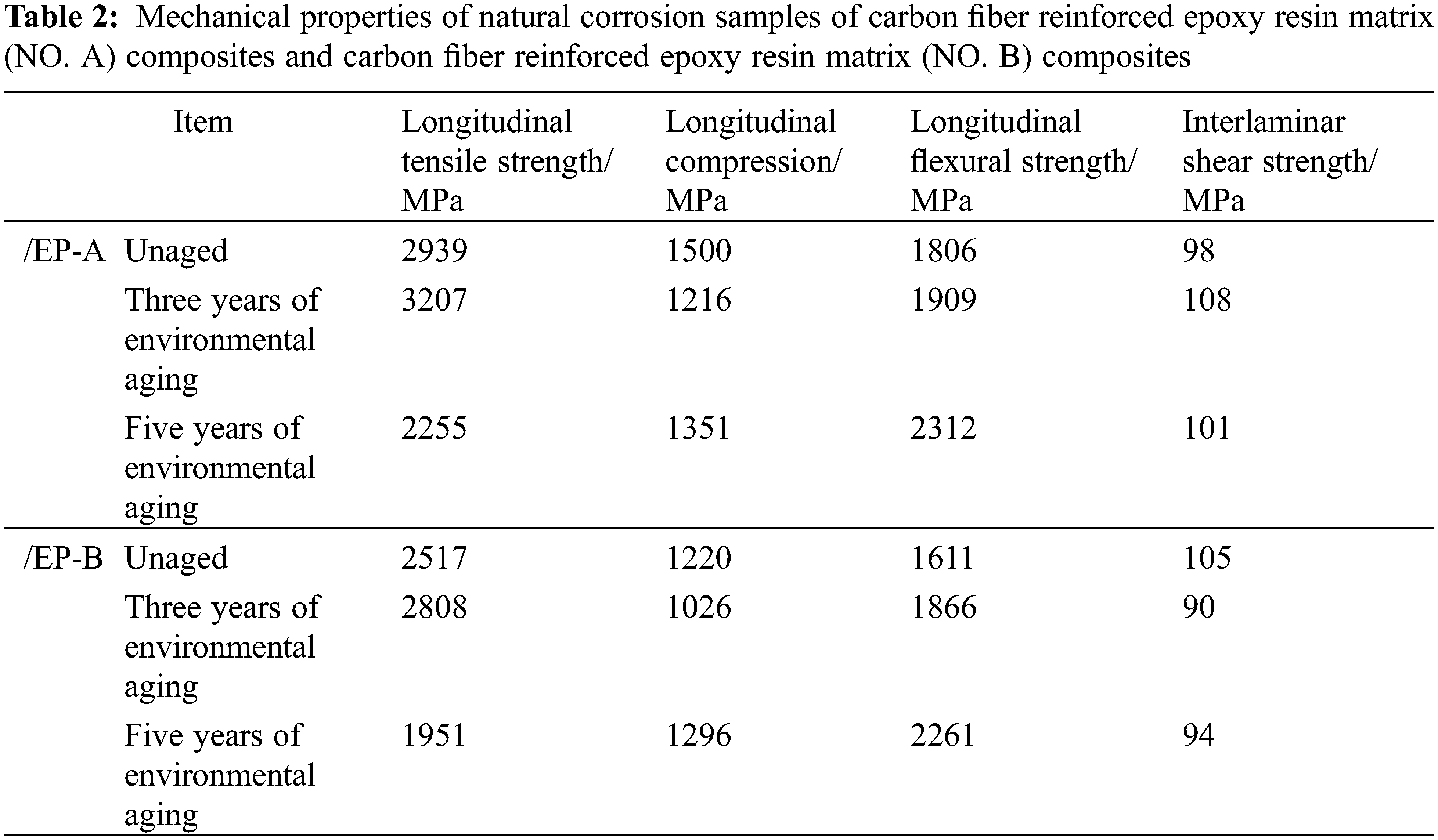
Figure 7: Tg of carbon fiber reinforced epoxy resin matrix (NO. A) composites with natural corrosion samples
Figure 8: Remaining mechanical property retention rate of carbon fiber reinforced epoxy resin matrix (NO. A) composite and carbon fiber reinforced epoxy resin matrix (NO. B) composite material under natural corrosion
After three years of natural corrosion, the residual longitudinal compressive strength retention rate of carbon fiber reinforced epoxy resin matrix (NO. A) composites is 19% lower than that of unaged samples. A) The residual longitudinal compressive strength retention of the composites is 10% lower than that of the unaged samples. After three years of natural corrosion, the residual longitudinal compressive strength retention rate of the carbon fiber reinforced epoxy resin matrix (NO. B) composite was reduced by 15% compared with the unaged sample. After five years of natural corrosion, the carbon fiber reinforced epoxy resin matrix (NO. B) The retention of residual longitudinal compressive strength of the composite is 6% higher than that of the unaged sample [15]. The above data show that the retention rate of residual longitudinal compressive strength of aged samples fluctuates up and down, but there is no apparent change trend. The longitudinal compressive strength of composites is also sensitive to the bonding force between the reinforcing fibers and the resin matrix. This phenomenon also proves that photooxidative aging and thermal-oxidative aging during the natural corrosion process are difficult to affect the internal reinforcing fibers and the matrix resin. Interface properties and adhesion.
After five years of natural corrosion, the carbon fiber reinforced epoxy resin matrix (NO. B) The residual flexural strength retention rate of the composite is 40% higher than that of the unaged sample. The above data show that with the prolongation of natural corrosion time, the longitudinal flexural strength of the aged specimens shows a gradually increasing trend. The longitudinal flexural strength of composites is mainly controlled by fiber properties and is also affected by matrix properties and interface properties. This phenomenon shows that the natural corrosion process does not cause a decrease in the properties of carbon fibers, and it plays a dominant role in the reinforcement effect of the composite material: under the long-term action of temperature, the resin matrix will cause the composite material to undergo a stress relaxation effect during the curing process. The thermal stress of the composite material is gradually released, and the resin matrix may transmit the load more effectively at this time, thereby improving the longitudinal bending strength of the composite material [16].
The mechanism may be the same as the increase of longitudinal bending strength. At this time, the enhancement effect of natural corrosion plays a leading role: under the long-term effect of temperature, the resin matrix will continue. Through the stress relaxation effect, the thermal stress generated during the curing process of the composite material is gradually released, and the matrix material can transmit the load more effectively, thereby improving the longitudinal tensile strength of the composite material. However, with the extension of natural corrosion time to 5 years, the damaging effect gradually dominates, the degradation degree of resin on the surface of the composite material gradually deepens, and there is no resin adhesion between the surface fibers. Therefore, the longitudinal tensile strength of the samples decreased after five years of natural corrosion.
With the continuous development of computer technology and the continuous improvement of electrochemical corrosion theory, corrosion simulation technology emerged. The technology is based on electrochemical principles. By testing the polarization properties of materials in different service environments, the finite element or boundary element method is used to predict the corrosion position and degree of the aircraft structure in a short period, which can significantly improve the aircraft’s anti-corrosion performance. Corrosion design ability, enriching corrosion resistance assessment methods, and correcting the model in combination with appropriate test verification. It can also be directly applied to the corrosion prediction of the whole aircraft, thereby eliminating the limitations of local critical parts assessment and achieving predictable aircraft corrosion. Purpose. Corrosion researchers at home and abroad have established simulation models of common corrosion forms such as galvanic corrosion, crevice corrosion, and pitting corrosion based on the application of finite element or boundary element simulation methods based on electrochemical principles. To meet lightweight or structural strength requirements during aircraft design, designers often have to couple different materials, such as steel-aluminum and aluminum-composite couplings. Although this type of coupling can make the aircraft meet the strength design requirements, due to the different electrochemical properties of different materials, coupling them can easily lead to galvanic corrosion, resulting in accelerated degradation of structural performance. Therefore, from the perspective of reliable design and maintenance of metal structures, it is crucial to accurately predict the occurrence area of galvanic corrosion and the corrosion reaction rate. These composite materials have very high mechanical properties, such as specific strength and modulus, so they are widely used to produce some structural and load-bearing parts in aerospace. Compared with metals and other materials, carbon fiber composite materials have many factors that affect the material’s mechanical properties due to the more complex manufacturing process. By adding fine particles, the combination of carbon fiber and matrix can be increased, thereby increasing composite materials’ tensile strength and fracture toughness. The characteristics of composite materials are small specific gravity, high specific strength, and large specific modulus. Its main advantage is that it can manufacture large, complex shapes with high fiber volume content. Its structural design efficiency is high, and its manufacturability is strong. Therefore, composite materials have become the most widely used material in modern industry. Resin transfer molding technology is the mainstream carbon fiber composite resin matrix manufacturing technology. To meet the needs of flow production of large-scale structural parts, the working viscosity of epoxy resin must be as low as possible, and the open period of the working state is also required to be relatively long. But high-flow resins are usually brittle after molding. The composition of the resin matrix is also a significant influencing factor. Still, the mechanism by which the microscopic composition of the resin matrix affects the mechanical properties of carbon fiber-reinforced composites remain to be studied.
Some scholars added 25% to 40% of ionic liquid to the epoxy resin matrix, respectively, and observed the change in mechanical properties of carbon fiber composites after adding ionic components. The experimental results show that with the increased ionic liquid concentration, the microstructure in the resin matrix is transformed, and the interfacial bonding strength and effective bonding area of carbon fibers are also reduced. Therefore, the ion concentration increase harms carbon fiber composites’ mechanical properties. The tensile strength of the composite material added with 40% ionic liquid is only 78% of the original, and the strength of the short beam is only 41% of the original. Fracture toughness is significantly reduced. The preparation process of carbon fiber reinforced resin matrix composites is relatively complex, and defects such as pores, inclusions, and cracks are usually formed, especially pores, which will significantly reduce the mechanical properties and performance of composite materials. Some scholars have tested the mechanical properties of carbon fiber reinforced composite laminates with different porosity. They found that in the laminates with porosity contents of 0.33%, 0.71%, and 1.5%, with the porosity, The tensile strength and compressive strength of the fabric carbon fiber reinforced epoxy resin laminate showed a downward trend.
After five years of natural corrosion, the surface resin matrix of carbon fiber reinforced epoxy resin matrix (NO. A) composites degrades and loses under the combined action of thermal oxidation aging and photooxidative aging. The degradation degree of the front side is higher than that of the backside. The glass transition temperature of the carbon fiber reinforced epoxy resin matrix (NO. A) composite material gradually decreased with the prolongation of natural corrosion time, and the Tg of the unaged sample of the carbon fiber reinforced epoxy resin matrix (NO. A) composite material was 207°C. After three years of natural corrosion treatment, its Tg was reduced to 180°C. When the natural corrosion time was extended to 5 years, its Tg was further reduced to 172°C.
Funding Statement: The author received no specific funding for this study.
Conflicts of Interest:: The author declares that they have no conflicts of interest to report regarding the present study.
References
1. Vu, C. M., Bach, Q. V., Vu, H. T., Nguyen, D. D., Kien, B. X. et al. (2020). Carbon-fiber-reinforced epoxy resin with sustainable additives from silk and rice husks for improved mode-I and mode-II interlaminar fracture toughness. Macromolecular Research, 28(1), 33–41. https://doi.org/10.1007/s13233-020-8010-7 [Google Scholar] [CrossRef]
2. Khalid, M. Y., Nasir, M. A., Ali, A., Al Rashid, A., Khan, M. R. (2020). Experimental and numerical characterization of tensile property of jute/carbon fabric reinforced epoxy hybrid composites. SN Applied Sciences, 2(4), 1–10. https://doi.org/10.1007/s42452-020-2403-2 [Google Scholar] [CrossRef]
3. Liu, Y. Y., Liu, G. L., Li, Y. D., Weng, Y., Zeng, J. B. (2021). Biobased high-performance epoxy vitrimer with UV shielding for recyclable carbon fiber reinforced composites. ACS Sustainable Chemistry & Engineering, 9(12), 4638–4647. https://doi.org/10.1021/acssuschemeng.1c00231 [Google Scholar] [CrossRef]
4. Zhang, W., Wu, J., Gao, L., Zhang, B., Jiang, J. et al. (2021). Recyclable, reprocessable, self-adhered and repairable carbon fiber reinforced polymers using full biobased matrices from camphoric acid and epoxidized soybean oil. Green Chemistry, 23(7), 2763–2772. https://doi.org/10.1039/D1GC00648G [Google Scholar] [CrossRef]
5. Liu, M., Rohde, B. J., Krishnamoorti, R., Robertson, M. L., Dawood, M. (2020). Bond behavior of epoxy resin-polydicyclopentadiene phase separated interpenetrating networks for adhering carbon fiber reinforced polymer to steel. Polymer Engineering & Science, 60(1), 104–112. https://doi.org/10.1002/pen.25264 [Google Scholar] [CrossRef]
6. Kumar, S., Krishnan, S. (2020). Recycling of carbon fiber with epoxy composites by chemical recycling for future perspective: A review. Chemical Papers, 74(11), 3785–3807. https://doi.org/10.1007/s11696-020-01198-y [Google Scholar] [CrossRef]
7. Baihaqi, N. N., Khalina, A., Nurazzi, N. M., Aisyah, H. A., Sapuan, S. M. et al. (2021). Effect of fiber content and their hybridization on bending and torsional strength of hybrid epoxy composites reinforced with carbon and sugar palm fibers. Polimery, 66(1), 36–43. https://doi.org/10.14314/polimery.2021.1.5 [Google Scholar] [CrossRef]
8. Singh, Y., Singh, J., Sharma, S., Aggarwal, V., Pruncu, C. I. (2021). Multi-objective optimization of kerf-taper and surface-roughness quality characteristics for cutting-operation on coir and carbon fibre reinforced epoxy hybrid polymeric composites during CO2-pulsed laser-cutting using RSM. Lasers in Manufacturing and Materials Processing, 8(2), 157–182. https://doi.org/10.1007/s40516-021-00142-6 [Google Scholar] [CrossRef]
9. Sheth, D., Maiti, S., Patel, S., Kandasamy, J., Chandan, M. R. et al. (2021). Enhancement of mechanical properties of carbon fiber reinforced epoxy matrix laminated composites with multiwalled carbon nanotubes. Fullerenes, Nanotubes and Carbon Nanostructures, 29(4), 288–294. https://doi.org/10.1080/1536383X.2020.1839424 [Google Scholar] [CrossRef]
10. Karuppannan Gopalraj, S., Kärki, T. (2020). A review on the recycling of waste carbon fibre/glass fibre-reinforced composites: Fibre recovery, properties and life-cycle analysis. SN Applied Sciences, 2(3), 1–21. https://doi.org/10.1007/s42452-020-2195-4 [Google Scholar] [CrossRef]
11. Muralidhara, B., Babu, S. K., Suresha, B. (2020). Studies on mechanical, thermal and tribological properties of carbon fibre-reinforced boron nitride-filled epoxy composites. High Performance Polymers, 32(9), 1061–1081. https://doi.org/10.1177/0954008320929396 [Google Scholar] [CrossRef]
12. Burkov, M. V., Eremin, A. V. (2021). Mechanical properties of carbon-fiber-reinforced epoxy composites modified by carbon micro-and nanofillers. Polymer Composites, 42(9), 4265–4276. https://doi.org/10.1002/pc.26144 [Google Scholar] [CrossRef]
13. Alsaadi, M., Erkliğ, A., Abbas, M. (2020). Effect of clay nanoparticles on the mechanical and vibration characteristics of intraply aramid/carbon fiber reinforced epoxy composite. Polymer Composites, 41(7), 2704–2712. https://doi.org/10.1002/pc.25568 [Google Scholar] [CrossRef]
14. Pathak, A. K., Garg, H., Subhedar, K. M., Dhakate, S. R. (2021). Significance of carbon fiber orientation on thermomechanical properties of carbon fiber reinforced epoxy composite. Fibers and Polymers, 22(7), 1923–1933. https://doi.org/10.1007/s12221-021-0703-9 [Google Scholar] [CrossRef]
15. Huang, Y., Liu, W., Jiang, Q., Wei, Y., Qiu, Y. (2020). Interlaminar fracture toughness of carbon-fiber-reinforced epoxy composites toughened by poly(phenylene oxide) particles. ACS Applied Polymer Materials, 2(8), 3114–3121. https://doi.org/10.1021/acsapm.0c00285 [Google Scholar] [CrossRef]
16. Singh, Y., Singh, J., Sharma, S., Lam, T. D., Nguyen, D. N. (2020). Fabrication and characterization of coir/carbon-fiber reinforced epoxy based hybrid composite for helmet shells and sports-good applications: Influence of fiber surface modifications on the mechanical, thermal and morphological properties. Journal of Materials Research and Technology, 9(6), 15593–15603. https://doi.org/10.1016/j.jmrt.2020.11.023 [Google Scholar] [CrossRef]
Cite This Article
 Copyright © 2023 The Author(s). Published by Tech Science Press.
This work is licensed under a Creative Commons Attribution 4.0 International License , which permits unrestricted use, distribution, and reproduction in any medium, provided the original work is properly cited.
 Downloads
 Citation Tools