
 Submit a Paper
 Propose a Special lssue
 Open Access
ARTICLE

Wave Reflection by Rectangular Breakwaters for Coastal Protection
Laboratory of Polymer Physics, Mechanical Sciences and Materials, Faculty of Sciences Ben M’Sik, Hassan II University of Casablanca, Casablanca, 20670, Morocco
* Corresponding Author: Hasna Akarni. Email:
Fluid Dynamics & Materials Processing 2024, 20(3), 579-593. https://doi.org/10.32604/fdmp.2023.043080
Received 21 June 2023; Accepted 20 September 2023; Issue published 12 January 2024
 View Full Text
 Download PDF
Abstract
In this study, we focus on the numerical modelling of the interaction between waves and submerged structures in the presence of a uniform flow current. Both the same and opposite senses of wave propagation are considered. The main objective is an understanding of the effect of the current and various geometrical parameters on the reflection coefficient. The wave used in the study is based on potential theory, and the submerged structures consist of two rectangular breakwaters positioned at a fixed distance from each other and attached to the bottom of a wave flume. The numerical modeling approach employed in this work relies on the Boundary Element Method (BEM). The results are compared with experimental data to validate the approach. The findings of the study demonstrate that the double rectangular breakwater configuration exhibits superior wave attenuation abilities if compared to a single rectangular breakwater, particularly at low wavenumbers. Furthermore, the study reveals that wave mitigation is more pronounced when the current and wave propagation are coplanar, whereas it is less effective in the case of opposing current.Keywords
One of the problems in the construction of coastal structures is their protection against wave action which may be partially reflected by changes in the seabed due to changes in depth. To reduce the impact of wave on coastal installations or natural shores, submerged obstacles are used [1–4], which act as wave reflectors and represent one of the most effective solutions to the problem of protecting the marine and coastal environment.
In order to comprehend the mechanisms of wave attenuation and dissipation better, several analytical, numerical, and experimental research on the hydrodynamic performance of various submerged structures have been carried out. Indeed, in 1993, Driscoll et al. [5] studied numerically and experimentally the harmonic evolution of linear monochromatic waves in a wave flume when propagating over a submerged impermeable rectangular obstacle. Davidson et al. [6] in 1996 proposed a novel non-dimensional parameter for analyzing wave reflection from rubble mound breakwaters, this parameter offers valuable insights into the wave interaction with such structures, aiding the understanding and design of breakwater systems. Later in 2001, Stamos et al. [7] carried out an experimental investigation to examine how rigid and flexible rectangular breakwater models, secured to the flume bottom at different immersion depths, impact the transmission, reflection, and energy dissipation of regular waves. They demonstrated that, generally speaking, the reflection due to the rigid model exceeds that of the flexible one. In 2008, Christou et al. [8] conducted a numerical analysis employing the Boundary Element Method (BEM) to accurately simulate the interaction between regular nonlinear waves with a submerged rectangular breakwater. An analytical second-order solution approach to effectively address the problem of wave propagation over a submerged rectangular structure was proposed by Lee et al. [9] in 2014. Recent studies in this field include those of Patil et al. [10], who used the Multi-Domain Boundary Element Method (MDBEM) to conduct a numerical analysis of the hydrodynamic performance of diverse types and forms submerged breakwaters. In addition, Kar et al. [11] in 2019 carried out a numerical study that relied on the boundary element method, this study aimed to investigate gravity wave transformation generated by a floating dock of finite size when it encountered sea bottom variations like trenches, breakwaters, and an appropriate combination of trenches and breakwaters. In 2020, Chanda et al. [12] investigated wave behavior and interaction with dynamic bottom topography, contributing to the understanding of wave dynamics in multi-layered fluid environments. The same authors [13] examined the impact of a porous seabed on wave diffusion, focusing on the interaction between waves and two vertically immersed thin porous plates. As well as Mahmoudof et al. [14] in 2021, they presented an experimental investigation of the reflection, transmission and dissipation of irregular waves on three forms of impermeable submerged breakwaters (rectangular breakwater, trapezoidal breakwater and U-form breakwater). In order to advance applied ocean research, the same authors [15] did a field experiment on wave reflection from the permeable rubble mound breakwater at Chabahar Port, by examining wave behavior in a practical port environment. In the same year, Fu et al. [16] investigated the wave dissipation performance of a submerged plate breakwater using the High-Order Finite-Difference Method (HOFDM). In 2022, Nguyen et al. [17] performed the experimental tests on three classes of breakwaters (hollow triangle, pile-rock, and semi-circular) in order to calculate the wave transmission, reflection, and dissipation coefficients.
In the ocean environment, the wave is usually accompanied by different currents that can be generated by winds, tides, river flows, etc. Therefore, the current’s presence must be considered when studying the behavior of the wave while it is interacting with submerged obstacles. This broad topic has been the subject of much research in maritime hydrodynamics, ocean engineering and other disciplines. Furthermore, due to the fact that the wave always accompanied by current, several numerical methods had been used to describe this interaction. In 2003, Ryu et al. [18] performed a numerical study based on the Boundary Element Method (BEM) of the nonlinear wave-uniform current interaction. Zhang et al. [19] in 2014 established a numerical model to study wave-current interaction. This model was formulated based on Reynolds-Averaged Navier-Stokes (RANS) equations with the k-ε turbulence closure scheme. Chang et al. [20] in 2016 simulated a combined wave-current flow in a truncated domain, used the Generation and Absorption Boundary Condition (GABC) of wave and current simultaneously. In 2016, Kim et al. [21] used the commercial software FLUENT to numerically explore the wave force on offshore substructures in the presence of a uniform current, they relied on the continuity and Navier-Stokes equations. Fan et al. [22] in 2018 applied the Generalized Finite Difference Method (GFDM) in combination with the Runge-Kutta method to study the wave propagation under the influence of current in inclined and horizontal bottom flumes. In 2019, Gholamipoor et al. [23] proposed a Meshless Method for simulating completely time-domain nonlinear wave-wave and wave-current interactions. To analyze the nonlinear wave resonance generated by the oscillations of two cylinders in a uniform current, a numerical study by the High-Order Finite Element Method (HOFEM) with an eight-node element was proposed by Huang et al. [24] in 2022.
In related to the same topic, many investigators have examined the influence of the current on the interaction between waves and submerged obstacles [25–30]. In 2015, Liang et al. [27] presented a numerical investigation employing a non-hydrostatic wave model to analyze wave transmission over dual submerged trapezoidal breakwaters in present of the current. Bai et al. [28] in 2017 studied the forces applied to a horizontal cylinder when a wave passes in the presence of a sheared current. The propagation of a nonlinear wave on a rectangular breakwater immersed on a flat seabed in presence of the current was investigated both numerically and experimentally by Chen et al. [29] in 2017. Naasse et al. [30] in 2019 analytically studied the wave-plate-current interaction taking on consideration the evanescent modes model, they examined the complex dynamics of this interaction by focusing on the impact of geometrical parameters. In 2021, Akarni et al. [31] numerically investigated the influence of the geometry of a totally immersed horizontal plate on the wave reflection in the presence of current.
In the context of the same subject matter, with a focus on enhancing the efficiency of the breakwater attenuator amid various occurring phenomena, this study was conducted to determine optimal breakwater dimensions capable of offering superior protection against the influences of waves and currents. This was achieved through the utilization of a computational framework. The framework entails a numerical representation of two closely spaced rectangular breakwaters affixed to the bottom of a wave flume, accounting for wave propagation when a uniform current is present. The model is founded upon the Boundary Element Method (BEM), and comprehensive numerical experiments are conducted to systematically explore the impact of both the current velocity and geometric parameters on the resulting reflection coefficient. A confrontation between our results and those of the experiment is presented to validate the proposed approach.
We assume a monochromatic incident wave of low amplitude
A breakwater system fixed on the bottom of a wave flume consisting of two rectangular obstacles spaced at a distance
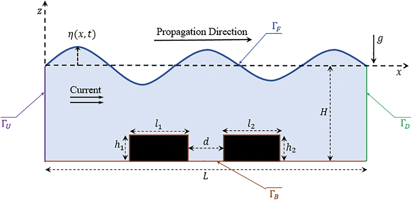
Figure 1: Descriptive schema of the study domain
The linear wave theory adopted in this work requires the following hypothesis, the flow is two-dimensional, periodic and irrotational. The surface tension is neglected and the fluid is assumed to be homogeneous, inviscid, heavy and incompressible. Furthermore this theory is based on the determination of velocity potential
The velocity potential
With:
where
The velocity potential associated with the linear wave must verify the following equations [18]:
In the study domain
The impermeability condition at the bottom:
The kinematic condition at the free surface:
The dynamic condition at the free surface:
The basic idea of the integral formulation of the Boundary Element Method (BEM) is to transpose the internal problem to the boundary using Green’s identity. The application of Green’s second identity allows the wave velocity potential
where
The Laplace equation in two dimensions is represented by the Green’s function
where
The domain boundary
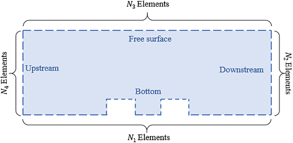
Figure 2: Domain discretization
Each segment has a length of
The influence matrices
• For
• For
As a result, the new matrix form of Eq. (10) is as follows:
In this system the number of equations is inferior to the number of unknowns (
• Boundary condition on
The bottom of the flume and the solid surfaces of the structures fixed on the bottom (i.e., the boundary
• Boundary condition on
In the absence of current at the free surface, we can write [20]:
where
Using Eq. (13), the free-surface condition in the presence of uniform current can be written [31]:
• Boundary condition on
Downstream, the wave is assumed to propagate without reflection, we can write:
So we can deduce the downstream condition [31]:
• Boundary condition on
Upstream, when the wave encounters a change in depth, it is partly reflected and partly transmitted. We will have on the upstream boundary
Knowing that the potential and its normal derivative upstream are continuous, we can write:
With
The upstream condition can be rewritten as [31]:
With:
where
Finally, the boundary conditions can be expressed as follows:
By injecting Eq. (24) into Eq. (11), the determination of the wave velocity potential
The numerical solution of the Eq. (25) can be done in a classical way by the Gauss method. When applying the numerical method, the correlation
• Reflection coefficient
The reflection coefficient
Since the reflection coefficient
4.1 Validation (Without Current
In this part, the proposed numerical approach will be validated by a comparative study of its results with the experimental ones. In order to do that, we are interested on one hand in the experiment of Driscoll et al. [5] concerning a rectangular breakwater of length
The comparison concerns the variation of the reflection coefficient
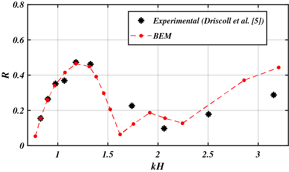
Figure 3: Comparative study of the variation of
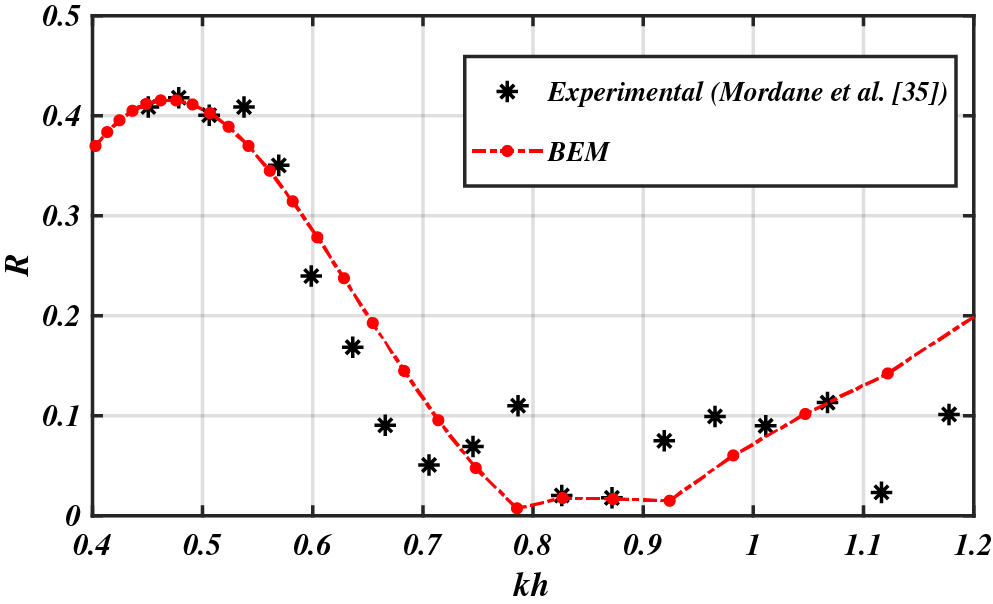
Figure 4: Comparative study of the variation of
4.2 Wave-Rectangular Breakwaters-Current Interaction
4.2.1 Comparison between a Single and a Double Rectangular Breakwater
In this part, a comparison between a rectangular breakwater and an identical double rectangular one is presented in order to show the importance of using this type of geometry. The configurations are taking at the same height
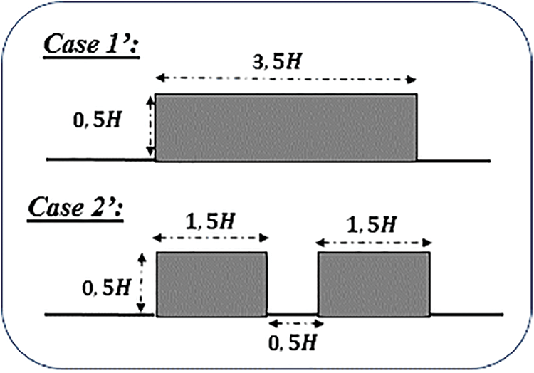
Figure 5: The different configurations
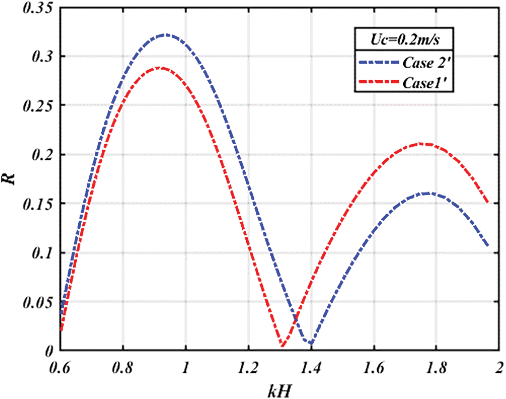
Figure 6: Variation of
The results of the comparative study show that the maximum reflection coefficient of the different configurations is around
It is clear that in case 2’, a reflection superposition phenomenon occurs, involving both the first and second breakwaters. When short-wavelength waves encounter this scenario, they are unable to reach the second breakwater, leading to an overall reflection confined to the contribution of the first breakwater. Consequently, the maximum reflection coefficient in case 2’ is lower due to the shorter length of the breakwater, in contrast to case 1’.
Conversely, in the presence of long-wavelength waves, they are able to reach the second breakwater, leading to a combined effect of reflections from both breakwaters. This results in a higher maximum reflection coefficient in case 2’ compared to the first, attributed to the additive nature of the two reflections.
4.2.2 The Case of Two Identical Rectangular Breakwaters
This part is dedicated to the study of the influence of two identical rectangular breakwaters (of the same length
• Effect of the current
Firstly, we are interested in studying the influence of the current velocity on the maximum value of the reflection coefficient and the width of the reflection band for different cases of the currents; without current, coplanar current and opposing current (Fig. 7).
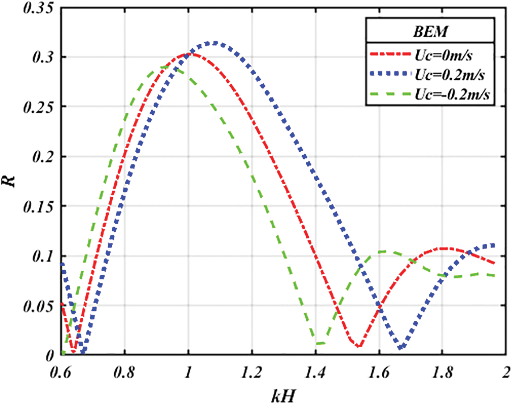
Figure 7: Variation of
According to Fig. 7, we note that if the current is flowing in in the same direction to that of the incident wave (
• Effects of the geometrical parameters
In this part, we are interested in the effect of geometrical parameters on the reflection coefficient in the presence of current. These geometrical parameters are the length and height of two rectangular breakwaters and the spacing between them. Where calculations have been made in the presence of a current velocity
• Effect of the length of two rectangular breakwaters
We are interested in studying the effect of the length of two breakwaters on the reflection coefficient
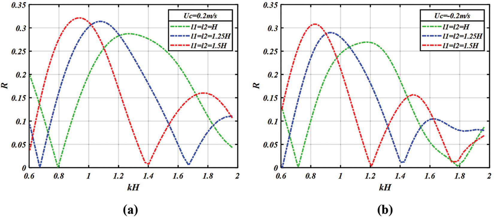
Figure 8: Variation of
• Effect of the height of two rectangular breakwaters
We now present the effect of the height of two breakwaters on the reflection coefficient
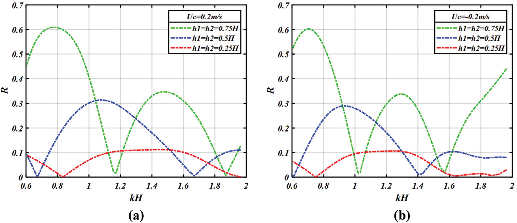
Figure 9: Variation of
• Effect of the distance
To study the influence of the spacing between the two breakwaters on the reflection coefficient in the presence of current, we depict the variations of this coefficient for different spacing (d = 0.5 H, 0.75 H and H). Based on the curves shown in Fig. 10, we notice that for the first band the maximum value of the reflection coefficient increases when the spacing between the two rectangular breakwaters
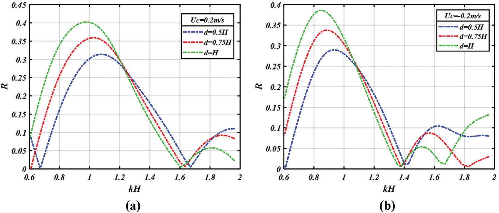
Figure 10: Variation of
4.2.3 The Case of Two Different Rectangular Breakwaters
In this part, we will present a comparison between different configurations by studying the variation of the reflection coefficient in the presence of a current velocity
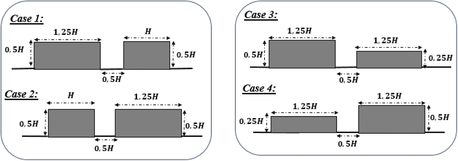
Figure 11: The different configurations
The curves illustrated in Fig. 12 show that whatever the position of two breakwaters of the same height with different lengths (Case 1 and Case 2) or of the same length with different heights (Case 3 and Case 4), the variation of the reflection remains practically unchanged.
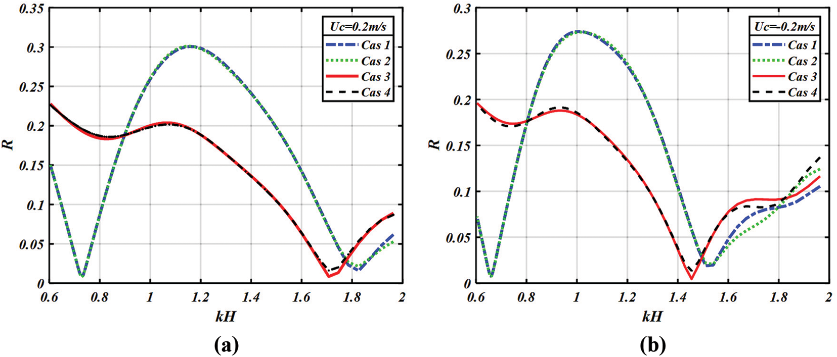
Figure 12: Variation of
The current study focused on numerically investigating the interaction between waves and two rectangular breakwaters positioned at a certain distance from each other and fixed to the flat bottom of a wave flume. This investigation was carried out considering the presence of a uniform current. To validate the numerical approach based on the Boundary Element Method (BEM), a comparison with experimental results was conducted. The aim was to gain a better understanding of the mechanisms involved in wave attenuation and dissipation when the current is present, by studying the influence of the current velocity and the geometric parameters of the two rectangular breakwaters on the reflection bandwidth and the maximum reflection coefficient.
Based on our findings, we can conclude that the double rectangular breakwater provides better wave attenuation compared to a single breakwater, particularly for low wavenumbers. Furthermore, in the presence of a coplanar current, both the reflection bandwidth and the maximum reflection coefficient increase. Conversely, in the case of an opposing current, these parameters decrease. Additionally, as the length and height of two rectangular breakwaters and the spacing between them increase, the maximum reflection coefficient also increases, this implies an important reduction of the wave.
Acknowledgement: The authors do not have special thanks for this study.
Funding Statement: The authors received no specific funding for this study.
Author Contributions: Conceptualization, H.A., H.M., L.E.A. and S.M.; methodology, H.A., H.M., L.E.A. and S.M.; software, H.A., H.M., L.E.A. and S.M.; validation, H.A., H.M., L.E.A. and S.M.; investigation, H.A., H.M., L.E.A. and S.M.; writing-original draft preparation, H.A., H.M., L.E.A. and S.M.; writing-review and editing, H.A., H.M., L.E.A. and S.M.; visualization, H.A., H.M., L.E.A. and S.M.; supervision, H.A., H.M., L.E.A. and S.M. All authors have read and agreed to the published version of the manuscript.
Availability of Data and Materials: Not applicable.
Conflicts of Interest: The authors declare that they have no conflicts of interest to report regarding the present study.
References
1. El Aarabi, L., Mouakkir, L., Mordane, S. (2020). Numerical modeling of the wave-structure interaction using the boundary element method. software engineering perspectives in intelligent systems. Proceedings of 4th Computational Methods in Systems and Software, pp. 292–303. Cham: Springer International Publishing. [Google Scholar]
2. Shih, R. S., Weng, W. K., Li, C. Y. (2020). Characteristics of wave attenuation due to roughness of stepped obstacles. Ships and Offshore Structures, 15(6), 605–619. [Google Scholar]
3. Rey, V., Belzons, M., Guazzelli, E. (1992). Propagation of surface gravity waves over a rectangular submerged bar. Ships and Offshore Structures, 235, 453–479. [Google Scholar]
4. Romya, A. A., Moghazy, H. M., Iskander, M. M., Abdelrazek, A. M. (2022). Performance assessment of corrugated semi-circular breakwaters for coastal protection. Alexandria Engineering Journal, 61(5), 3587–3598. [Google Scholar]
5. Driscoll, A. M., Dalrymple, R. A., Grilli, S. T. (1993). Harmonic generation and transmission past a submerged rectangular obstacle. 23rd International Conference in Coastal Engineering, pp. 1142–1152. New York, USA: American Society of Civil Engineers. [Google Scholar]
6. Davidson, M. A., Bird, P. A. D., Bullock, G. N., Huntley, D. A. (1996). A new non-dimensional number for the analysis of wave reflection from rubble mound breakwaters. Coastal Engineering, 28(1–4), 93–120. [Google Scholar]
7. Stamos, D. G., Hajj, M. R. (2001). Reflection and transmission of waves over submerged breakwaters. Journal of Engineering Mechanics, 127(2), 99–105. [Google Scholar]
8. Christou, M., Swan, C., Gudmestad, O. (2008). The interaction of surface water waves with submerged breakwaters. Coastal Engineering, 55(12), 945–958. [Google Scholar]
9. Lee, J. F., Tu, L. F., Liu, C. C. (2014). Nonlinear wave evolution above rectangular submerged structures. Journal of Marine Science and Technology, 22(5), 531–541. [Google Scholar]
10. Patil, S. B., Karmakar, D. (2021). Performance evaluation of submerged breakwater using Multi-Domain Boundary Element Method. Applied Ocean Research, 114, 102760. [Google Scholar]
11. Kar, P., Sahoo, T., Behera, H. (2019). Effect of bragg scattering due to bottom undulation on a floating dock. Wave Motion, 90, 121–138. [Google Scholar]
12. Chanda, A., Bora, S. N. (2020). Propagation of oblique waves over a small undulating elastic bottom topography in a two-layer fluid flowing through a channel. International Journal of Applied Mechanics, 12(2), 2050023. [Google Scholar]
13. Chanda, A., Bora, S. N. (2020). Effect of a porous sea-bed on water wave scattering by two thin vertical submerged porous plates. European Journal of Mechanics-B/Fluids, 84, 250–261. [Google Scholar]
14. Mahmoudof, S. M., Hajivalie, F. (2021). Experimental study of hydraulic response of smooth submerged breakwaters to irregular waves. Oceanologia, 63(4), 448–462. [Google Scholar]
15. Mahmoudof, S. M., Eyhavand-Koohzadi, A., Bagheri, M. (2021). Field study of wave reflection from permeable rubble mound breakwater of Chabahar Port. Applied Ocean Research, 114, 102786. [Google Scholar]
16. Fu, D., Zhao, X., Wang, S., Yan, D. (2021). Numerical study on the wave dissipating performance of a submerged heaving plate breakwater. Ocean Engineering, 219, 108310. [Google Scholar]
17. Nguyen, N. M., Van, D. D., Le, D. T., Cong, S. D., Pham, N. T. et al. (2022). Wave reduction efficiency for three classes of breakwaters on the coastal Mekong Delta. Applied Ocean Research, 129, 103362. [Google Scholar]
18. Ryu, S., Kim, M., Lynett, P. J. (2003). Fully nonlinear wave-current interactions and kinematics by a BEM-based numerical wave tank. Computational Mechanics, 32(4), 336–346. [Google Scholar]
19. Zhang, J. S., Zhang, Y., Jeng, D. S., Liu, P. F., Zhang, C. (2014). Numerical simulation of wave--current interaction using a RANS solver. Ocean Engineering, 75, 157–164. [Google Scholar]
20. Chang, X., Akkerman, I., Huijsmans, R. H., Veldman, A. E. (2016). Generating and absorbing boundary conditions for combined wave-current simulations. Proceedings of the 12th International Conference on Hydrodynamics, Delft, Netherlands. [Google Scholar]
21. Kim, S. Y., Kim, K. M., Park, J. C., Jeon, G. M., Chun, H. H. (2016). Numerical simulation of wave and current interaction with a fixed offshore substructure. International Journal of naval Architecture and Ocean Engineering, 8(2), 188–197. [Google Scholar]
22. Fan, C. M., Chu, C. N., Šarler, B., Li, T. H. (2019). Numerical solutions of waves-current interactions by generalized finite difference method. Engineering Analysis with Boundary Elements, 100, 150–163. [Google Scholar]
23. Gholamipoor, M., Ghiasi, M. (2019). A meshless numerical wave tank for simulation of fully nonlinear wave--wave and wave--current interactions. Journal of Engineering Mathematics, 119(1), 115–133. [Google Scholar]
24. Huang, H. C., Yang, Y. F., Zhu, R. H., Wang, C. Z. (2022). Nonlinear wave resonance due to oscillations of twin cylinders in a uniform current. Applied Ocean Research, 121, 103096. [Google Scholar]
25. Shih, R. S., Li, C. Y., Weng, W. K. (2019). Wave-structure-current interactions over smooth and rough breakwaters. Ships and Offshore Structures, 17(1), 29–50. [Google Scholar]
26. Errifaiy, M., Naasse, S., Chahine, C. (2016). Analytical determination of the reflection coefficient by the evanescent modes model during the wave--current--horizontal plate interaction. Comptes Rendus Mécaniques, 344(7), 479–486. [Google Scholar]
27. Liang, B., Wu, G., Liu, F., Fan, H., Li, H. (2015). Numerical study of wave transmission over double submerged breakwaters using non-hydrostatic wave model. Oceanologia, 57(4), 308–317. [Google Scholar]
28. Bai, J., Ma, N., Gu, X. (2017). Study of interaction between wave-current and the horizontal cylinder located near the free surface. Applied Ocean Research, 67, 44–58. [Google Scholar]
29. Chen, L. F., Ning, D. Z., Teng, B., Zhao, M. (2017). Numerical and experimental investigation of nonlinear wave-current propagation over a submerged breakwater. Journal of Engineering Mechanics, 143(9), 04017061. [Google Scholar]
30. Naasse, S., Errifaiy, M., Chahine, C. (2019). Analytical study of the effect of the geometrical parameters during the interaction of regular wave-horizontal plate-current. Acta Oceanologica Sinica, 38(5), 10–20. [Google Scholar]
31. Akarni, H., El Aarabi, L., Mouakkir, L., Mordane, S. (2021). Numerical modeling of the wave-plate-current interaction by the Boundary Element Method. Fluids, 6(12), 435. [Google Scholar]
32. Ning, D. Z., Lin, H. X., Teng, B., Zou, Q. P. (2014). Higher harmonics induced by waves propagating over a submerged obstacle in the presence of uniform current. China Ocean Engineering, 28, 725–738. [Google Scholar]
33. Lee, J. J. (1971). Wave-induced oscillations in harbours of arbitrary geometry. Journal of Fluid Mechanics, 45(2), 375–394. [Google Scholar]
34. Dabsi, N. (1998). Modélisation numérique des oscillations induites dans un port sollicité par une houle incidente et étude du comportement d’un navire marré (Ph.D. Thesis). Hassan II University of Casablanca, Morocco. [Google Scholar]
35. Mordane, S. (2001). Contribution numérique à la résolution du problème d’interaction houle-obstacles (Ph.D. Thesis). Hassan II University of Casablanca, Morocco. [Google Scholar]
Cite This Article
 Copyright © 2024 The Author(s). Published by Tech Science Press.
This work is licensed under a Creative Commons Attribution 4.0 International License , which permits unrestricted use, distribution, and reproduction in any medium, provided the original work is properly cited.
 Downloads
 Citation Tools