
 Submit a Paper
 Propose a Special lssue
 Open Access
ARTICLE

Structural Optimization of Nozzles for Gas-Liquid Two-Phase Jets
1 School of Petroleum Engineering, Shandong Institute of Petroleum and Chemical Technology, Dongying, 257061, China
2 School of Petroleum Engineering, China University of Petroleum (East China), Qingdao, 266580, China
3 Dongying Academy of Science and Technology, China University of Petroleum (East China), Dongying, 257061, China
4 CNOOC (Tianjin) Oilfield Chemical Co., Ltd., Tianjin, 300451, China
* Corresponding Author: Jian Zhao. Email:
Fluid Dynamics & Materials Processing 2025, 21(12), 2963-2980. https://doi.org/10.32604/fdmp.2025.073836
Received 26 September 2025; Accepted 21 November 2025; Issue published 31 December 2025
 View Full Text
 Download PDF
Abstract
Gas–liquid two-phase jets exhibit markedly enhanced impact performance due to the violent collapse of entrained bubbles, which generates transient microjets and shock waves. The geometry of the nozzle is a decisive factor in controlling jet formation, flow modulation, and impact efficiency. In this work, the structural optimization of gas–liquid two-phase nozzles was investigated numerically using the Volume of Fluid (VOF). Simulation results show that the aero-shaped nozzle delivers a significantly stronger impact on the target surface than conventional geometries. Specifically, its impact pressure is 21% higher than that of a conical straight nozzle and 37% higher than that of a conical nozzle. The aero nozzle not only increases peak impact pressure but also sustains it over a longer duration, leading to an overall improvement in energy transfer efficiency. Parametric analyses further reveal the key geometric conditions governing performance. When the nozzle curvature is set to 0.01, the jet achieves a higher and more stable surface pressure profile, maintaining elevated impact for a prolonged period. At an aspect ratio of 15, the jet exhibits pronounced pulsation under high pressure, thereby enhancing impact intensity. The contraction ratio exerts a non-monotonic influence: as it increases, impact pressure initially rises and subsequently declines, with an optimal value of 4 yielding the highest and most persistent impact pressure. Likewise, when the ratio of inlet length to outlet diameter is 2.5, the jet demonstrates the strongest impact on the target surface.Graphic Abstract
Keywords
Water jet technology [1] has been widely applied in various fields such as shipbuilding, chemical machinery, power industry, petroleum engineering, and aerospace [2,3,4,5]. The application of this technology improves production efficiency, reduces production cost and staff workload, and increases economic benefits for enterprises and society. Water jet technology is subdivided into various forms of jets, including pure water jet, abrasive jet, cavitation jet, pulse jet, and gas-liquid two-phase jet [6,7,8,9,10,11]. Compared with the pure water jet, the gas-liquid two-phase jet can generate an instantaneous high-speed micro-jet and shock-wave, while bubbles collapse [12], which can effectively improve the impact power of the jet that is suitable for various industrial applications. The nozzle is the key to generating a jet and has a significant influence on the modulation and efficiency of the impact of the jet.
Cavitation nozzles were designed for the submerged state, mainly including central body nozzles, overlapping nozzles, and nozzles with cylindrical outlet sections. The excellent erosion resistance of the cavitation nozzle was verified by experiments [13]. Moreover, the sharp angles of the triangle in the triangular nozzle could cause asymmetric distribution of velocity and pressure, though this characteristic could increase the mixing of fluids [14]. Compared to nozzles with sharp edges, a nozzle with a circular outlet has higher flow coefficients [15]. The shape of the jet from a nozzle with sharp edges can be divided into a continuous zone, a discrete zone, and an atomization zone. The length and the evolution state of each zone are affected by the shape of the nozzle’s outlet [16]. The influence of structural parameters of a nozzle on the energy loss of the jet was studied, and the results showed that the closer the inner flow channel of the nozzle to a streamline, the smaller the energy loss of the jet [17]. A previous work [18] studied the flow field characteristics of a nozzle near the wall at low Reynolds numbers using the large eddy simulation method. The results showed that frictional resistance mainly occurred at the end of the convergence section and the throat area, while the viscous force was distributed in the convergence section. The effects of four typical nozzle internal flow patterns on the spray primary breakup in the near-nozzle region were investigated based on the volume-of-fluid (VOF) method through the design and construction of corresponding nozzle structures [19]. The impact pressure was high and stable with an organ tube self-oscillating cavitation jet nozzle, while the Helmholtz type cavitation jet nozzle had a high pulse frequency and a long distance of bubble movement. For the angular cavitation jet nozzle, the ability of the jet to diffuse was strong, whereas the degree of cavitation was high. Additionally, there were velocity distributions of an inverted “U” shape and a large range of cavitation with a rotating cavitation jet nozzle of impeller type [20]. The internal flow field of the heavy oil viscosity reduction spray nozzle device, which is designed by the jet cavitation theory using the Computational Fluid Dynamics numerical simulation method. The influence of spray nozzle structural parameters such as inlet diameter, contraction length, and expansion length on the cavitation effect of the spray nozzle is studied [21]. The kinematics and entrainment characteristics of the cavitation bubble-induced jet were studied with the experimental method [22]. The flow field characteristics of a cylindrical cavitation nozzle jet under different turbulence models were systematically investigated. The results showed that the LES and SBES models demonstrated superior capability in capturing small-scale vortices and transient cavitation clouds, aligning more closely with the experimental observations [23]. The flow field morphology and jet performance through a nozzle were studied using numerical computational and indoor experimental methods [24,25,26]. The flow field and oscillating mechanism of the self-excited oscillating cavity were simulated using the large eddy simulation method of Computational Fluid Dynamics (CFD) [27]. By high-speed camera visualisation experiments and large eddy simulation, the influence of nozzle structure parameters on jet morphology evolution and cavitation impact characteristics was studied [28,29]. The cleaning effect of the nozzle with different structural designs was simulated, and the nozzle in the jet structure was optimized. The design variables include the geometric parameters of the nozzle's structure and the flow process parameters of the jet [30,31].
The present paper studies the structural optimization of a nozzle with a gas-liquid two-phase jet using the computational fluid dynamics (CFD)’s fluid volume method. CFD is a technology to simulate the motion characteristics and physical phenomena of fluids with the help of computers. The actual fluid flow can be approximately simulated by numerically solving differential equations of flow control, and the discrete distribution of the flow field was obtained in a continuous region. A complex flow field can be simulated, providing comprehensive flow field information at low cost and without physical model limitations by utilizing CFD technology. The study reveals the influence of the nozzle’s structure on the modulation characteristics and efficiency of the impact of the gas-liquid two-phase jet. The research provides theoretical guidance and parametric support for the application of gas-liquid two-phase jets in various industries.
To study the changes in the nozzle’s flow field in the gas-liquid two-phase jet, the VOF (volume of fluid) model was employed for numerical simulations using the software package of Fluent. Water and air were used as the liquid and gas phases, respectively.
The basic governing equations are as follows [32,33].
- (1)Continuity equation is given by Eq. (1).
- (2)Momentum equation is given by Eq. (2).
- (3)Equation of volume fractions is given by Eq. (5).
For phase q:
The volume fraction of the main phase is calculated based on the constraints given in Eq. (6).
- (4)Turbulence model is given by Eqs. (7) and (8).
Standard k–ε model was utilized to calculate the turbulence of the fluid [33], as given by Eqs. (7) and (8).
Based on the Eulerian-Eulerian non-homogeneous flow model, transient flow was selected. For the purpose of simulation, the calculations were based on a pressure solver, without considering the slip between phases. The standard k-ε model was adopted, and the standard wall function was used near the wall in the simulation. Moreover,
2.2 Geometric Model and Boundary Conditions
Frequently used jet nozzles [34,35] include three categories: conical nozzle, conical straight nozzle, and aero nozzle. The diameter of the nozzle’s inlet (D), diameter of the nozzle’s outlet (d), contraction angle of the nozzle (θ), length of the inlet section (L1) and length of the shrinkage section (L) had values of 8 mm, 2 mm, 13°, 5 mm, and 26.5 mm, respectively, as shown in Fig. 1.
Figure 1: Structures of the three nozzles. (a) Conical nozzle; (b) Conical straight nozzle; (c) Aero nozzle.
The software package of Solidworks (2023) was used to establish a three-dimensional (3D) model. Moreover, the software package of ANSYS was utilized to generate a mesh. For simulation, the number of grids has an influence on the results of the solution. When the number of grids is too small, the calculated results will not be accurate enough. It will increase computational complexity to increase the number of grids. Therefore, it is necessary to choose a reasonable grid size to ensure the accuracy of results. Grid independence was verified by dividing the model into grids with sizes of 3 mm, 2 mm, 1 mm, and 0.7 mm.
The velocity profile was obtained along the nozzle’s axis, as shown in Fig. 2. When the grid size decreased, the velocity along the nozzle’s axis tended to stabilize. Velocities obtained by dividing the grid by 1 mm and 0.7 mm were similar, whereas the number of elements divided by 0.7 mm (559759) was approximately twice as high as that divided by 1 mm (285005). With the increase of mesh density, the variation of velocity at a distance of 0.030 m from the nozzle inlet along the nozzle’s axis was shown in Table 1. When the grid size was reduced from 1 mm to 0.7 mm, the velocity only increased by 0.1%. In short, the grid size had been determined to be 1 mm and localized encryption was carried out near the nozzle outlet to ensure the accuracy of simulation results, as shown in Fig. 3. The surfaces were set up, such as the inlet, wall, outlet, and targeted surface.
Table 1: Variation of velocity with the increase of mesh density.
| Grid Size/(mm) | Velocity at a Distance of 0.030 m from Nozzle Inlet/(m·s−1) | Velocity Variation Rate/(%) |
|---|---|---|
| 3 | 314.6 | — |
| 2 | 320.8 | 1.97 |
| 1 | 323.9 | 0.96 |
| 0.7 | 324.2 | 0.09 |
Figure 2: Velocity profile along the nozzle’s axis for different grid sizes.
Figure 3: Grids of the three nozzle structures. (a) Grid of conical nozzle; (b) Grid of conical-straight nozzle; (c) Grid of aero nozzle.
The physical properties of water and air are presented in Table 2. Water is set as the primary phase, while air is set as the secondary phase. The volume fraction of the second phase is 0.1 (total volume to be unity). The mixture of gas and liquid phases enters from the inlet of the nozzle.
Table 2: Physical properties of liquid and gas phases.
| Fluid Material | Density/(kg·m−3) | Specific Heat/(J·kg−1·°C−1) | Thermal Conductivity/(W·m−1·°C−1) | Viscosity/(10−3 Pa·s) |
|---|---|---|---|---|
| Water | 998.2 | 4182 | 0.6 | 1.003 |
| Air | 1.225 | 1006.43 | 0.0242 | 1.78 |
The boundary conditions consisted of inlet velocity (the velocity was 18.75 m/s), pressure at the outlet (the outlet pressure was atmospheric pressure), and wall (the wall was stationary with no slip).
The PISO method was used for the pressure-velocity coupling solution. The format of second-order-upwind was adopted for discretization of momentum and turbulent kinetic energy. Volume fraction adopts Geo-reconstruct discrete format. The format of first-order-implicit was used for temporal discretization [36,37].
The conical straight nozzle, conical nozzle and aero nozzle were compared with each other. The optimum nozzle structure was selected. The dimensional parameters of the nozzle are presented in Table 3.
Table 3: Dimensional parameters of physical models used in simulation.
| Nozzle Type | Inlet Diameter D/mm | Outlet Diameter d/mm | Convergence Angle of Nozzle θ/(°) | Entrance Length L1/mm | Shrinkage Segment Length L/mm | Aspect Ratio | Arc Radius/mm | Arc Curvature |
|---|---|---|---|---|---|---|---|---|
| Aero nozzle | 8 | 2 | -- | 5 | 26.5 | -- | 100 | 0.01 |
| Conical straight nozzle | 8 | 2 | 13 | 5 | 26.5 | 3 | -- | -- |
| Conical nozzle | 8 | 2 | 13 | 5 | 26.5 | -- | -- | -- |
3.1 Influence of Nozzle Structure on the Maximum Impact Pressure of the Targeted Surface
To further compare the impact pressure of the gas-liquid two-phase jet on the targeted surface, a conical straight nozzle with the aspect ratio of 3, an aero nozzle with a curvature of 0.01, and a conical nozzle were selected for simulation. The pressure nephograms of the targeted surface for different types of nozzles are shown in Fig. 4.
Figure 4: Pressure nephogram of targeted surface for different nozzle structures. (a) Aero nozzle with the curvature of 0.01; (b) Conical straight nozzle with the aspect ratio of 3; (c) Conical nozzle.
The results showed that the maximum pressure of the aero nozzle with the curvature of 0.01 on the targeted surface was 36.3 MPa, whereas that of the conical straight nozzle with the aspect ratio of 3 was 30 MPa. Moreover, the maximum pressure of the conical nozzle was 26.5 MPa. Under the same conditions, the impact pressure of the aero nozzle on the targeted surface was 21% higher than that of the conical straight nozzle and 37% higher than that of the conical nozzle, indicating that the aero nozzle produced a greater impact pressure on the targeted surface and had a better impact effect. The aero nozzle has good impact performance, which is consistent with previous research results [38,39]. Due to the reason that an aero nozzle has a streamlined structure, it does not form vortices, avoiding the formation of local low-speed or backflow zones. This structure can reduce the loss of energy and improve the efficiency of the jet. In addition, the aero nozzle can reduce the shear stress between the fluid and the nozzle’s wall, thereby reducing frictional losses and improving the impact performance of the jet [40].
3.2 Effect of Nozzle Structures on the Pressure at the Center Point of the Targeted Surface
A monitoring point was set up at the center of the targeted surface to better compare the performances of the three nozzles. Variations in impact pressure for the three types of nozzles on the center point of the targeted surface are shown in Fig. 5.
Figure 5: Variation in pressure with time at the center point of targeted surface.
When the gas-liquid two-phase jet impacted the targeted surface, the pressure acting on the targeted surface fluctuated from high to low regardless of the structure of the nozzle. In gas-liquid two-phase flow, when the gas passes through the nozzle, the velocity increases while the pressure decreases, which can cause gas cavitation and generate a series of bubbles in the jet. Bubbles undergo four stages of cavitation, which are inception, development, shedding, and collapse [41]. With the decrease of environmental pressure, the initial high-pressure bubble expands to maximum size. When the external pressure of the bubble is greater than the internal pressure, the bubble begins to contract and collapse. The collapse of a bubble can cause high-speed micro jets, resulting in pressure peaks and strong impact forces on the target surface [42,43]. The bubbles undergo repeated cycles of expansion, compression, and even collapse, causing the impact pressure of the targeted surface to repeatedly increase and decrease. The phenomenon of repeated and continuous changes verifies that the gas-liquid two-phase jet has pulsating characteristics. The periodic pulsation phenomenon of a gas-liquid two-phase jet has been verified by physical experimental methods [44,45]. Therefore, the impact of the gas-liquid two-phase jet was better than pure water jet. The maximum impact pressure of the jet on the targeted surface varied depending on the structure of the nozzle. Moreover, the duration of high pressure also varied for different nozzles. Compared with conical straight nozzle and the conical nozzle, the peak value of the pressure curve at the center point of the targeted surface was the highest when the aero nozzle impacted the targeted surface. Meanwhile, the amplitude (or range) of high and low pressures was larger for the aero nozzle compared to the other two nozzles. The impact pressure generated by the gas-liquid two-phase jet was the highest, and the duration was longer at higher impact pressures. It is concluded that the aero nozzle has a greater intensity for the impact on the targeted surface and higher jet efficiency than the other two types of nozzles.
4 Flow Field Modulation Characteristics
The distribution patterns of the velocity field, the pressure field, the turbulent kinetic energy field, and the gas-liquid concentration are revealed by simulating the flow field with gas-liquid two-phase flow in an aero nozzle. The modulation mechanism of gas-liquid two-phase flow in an aero nozzle was elucidated. The flow rate for the simulation was set to be 60 L/min.
The non-dimensionalized velocity nephogram and vector diagram on the cross-section of the aero nozzle are shown in Fig. 6. The results showed that the high speed occurred at the position from approximately 3 times the nozzle diameter inside of the nozzle to approximately 2 times the nozzle diameter outside of the nozzle. As the cross-sectional area of the nozzle decreased, the jet velocity increased, and the velocity remained at a high value around the nozzle’s outlet. After the gas-liquid two-phase jet was ejected from the nozzle, the velocity inside the jet’s potential core remained high. There was no obvious backflow phenomenon in the flow field inside the nozzle. In the external flow field of the nozzle, near the targeted surface, significant vertical and tangential velocities were observed. The vertical velocity can be converted into impact pressure, while the tangential velocity is beneficial for the formation and expansion of cracks on the targeted surface, which is very advantageous for cleaning and cutting. There was a noticeable backflow near the targeted surface of the external flow field, which was beneficial for carrying away debris from cleaning and cutting processes.
Figure 6: Non-dimensionalized velocity distribution on the section of aero nozzle. (a) Velocity nephogram; (b) Velocity vector diagram.
The pressure nephogram on the section of the aero nozzle is shown in Fig. 7. When the gas-liquid two-phase jet entered the nozzle, the pressure gradually decreased. Moreover, the pressure dropped to an even lower value at the outlet of the nozzle. Near the targeted surface, the pressure decreased approximately in a spherical shape with the center of the targeted surface as the sphere’s center. According to Bernoulli’s principle, when the cross-section of the nozzle shrinks, the velocity increases and the pressure decreases. At the outlet of the nozzle, the cross-section was the smallest and the kinetic energy was the highest, resulting in the lowest pressure. When the jet impacted the targeted surface, kinetic energy was converted into stagnation pressure energy, and the pressure gradually increased [46].
Figure 7: Pressure nephogram on the section of aero nozzle.
4.3 Distribution of the Gas-Liquid Concentrations
The nephogram of the distribution of gas-liquid concentrations on the cross-section of the aero nozzle is shown in Fig. 8. There were obvious bubbles in the contracting section of the nozzle and near the targeted surface. In the nozzle’s contraction section, the decrease of the nozzle’s cross-sectional area led to an increase of flow velocity and decrease of pressure. Gas is more apt to cavitation and formation of bubbles under low pressure. When the bubbles near the targeted surface quickly collapse, strong shock waves, high temperatures, and high-speed microjets are generated [47]. This will cause local ultra-high impact pressure on the targeted surface, and the pressure turns far higher than the stagnation pressure. Therefore, the gas-liquid two-phase jet will have a good cleaning effect.
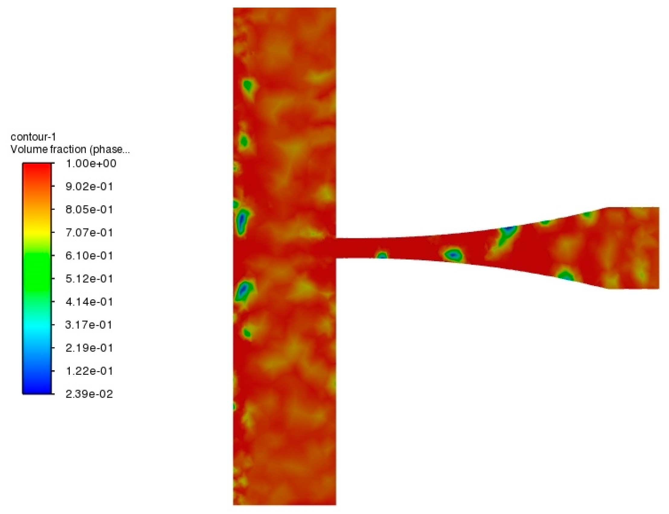
Figure 8: Distribution of the gas-liquid concentration in the aero nozzle’s cross-section.
The nephogram for the distribution of turbulent kinetic energy on the section of aero nozzle is shown in Fig. 9. The turbulent kinetic energy of the jet inside the nozzle was very small. After the jet was sprayed out of the nozzle, the turbulent kinetic energy increased significantly. There was a local maximum for the turbulent kinetic energy near the targeted surface, indicating that the level of turbulence of the jet was very high. Higher turbulence intensity is conducive to generating a large shear force on the targeted surface [14]. Turbulence makes the jet easily penetrate into small gaps or uneven surfaces. Moreover, the pressure fluctuations generated by turbulent flow were more intense. It is conducive to promoting the generation and collapse of bubbles and improving the impact of the gas-liquid two-phase jet.
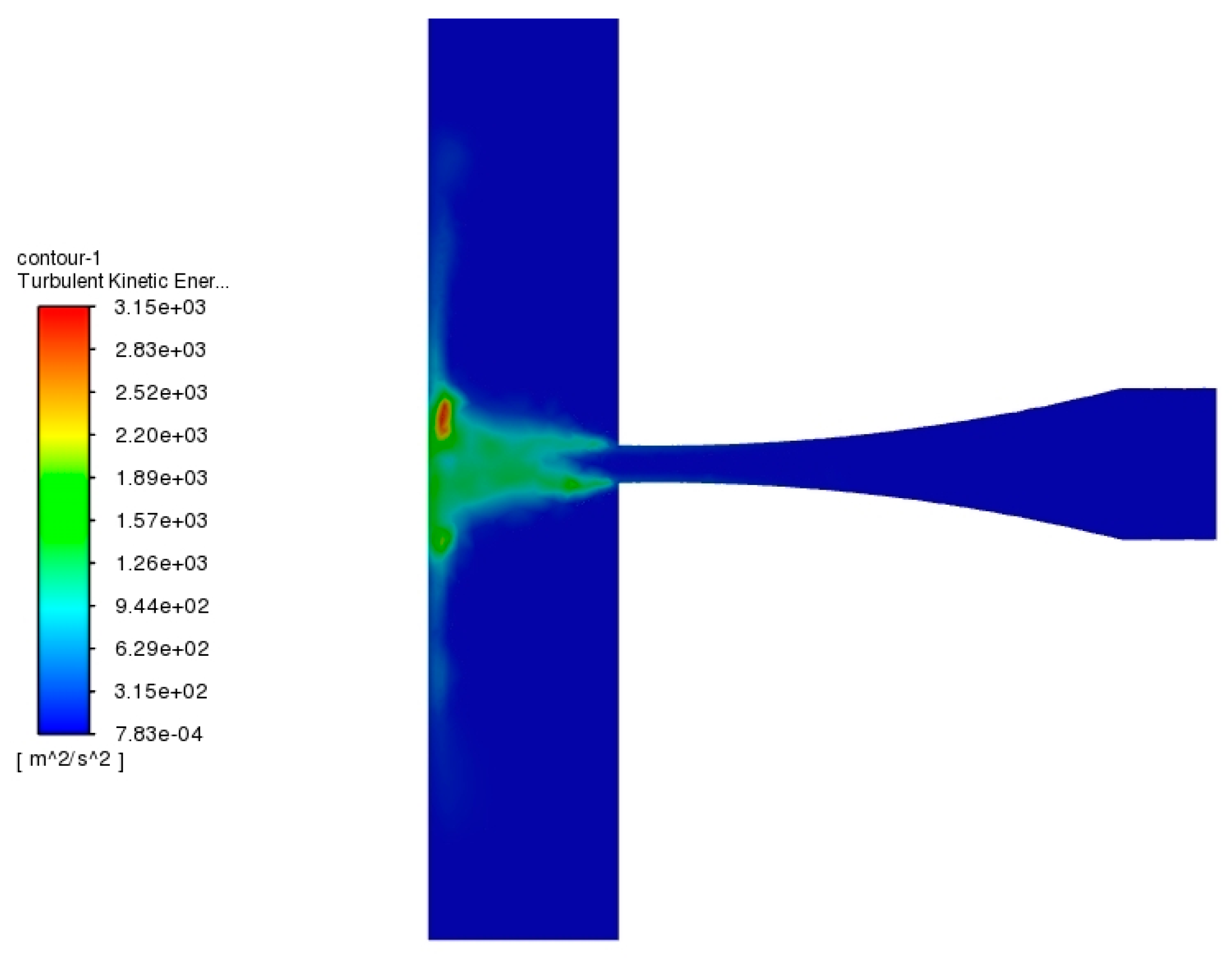
Figure 9: Nephogram of turbulent kinetic energy on the section of aero nozzle.
4.5 Modulation Mechanism of Gas-Liquid Two-Phase Jet
Fig. 10 illustrates the distribution of gas and liquid phases on the cross-section of the aero nozzle at different flow times. The gas-liquid two-phase distribution of a gas-liquid two-phase jet nozzle was numerically simulated during the time period from 0 s to 0.001 s. The results showed that the processes and phenomena have periodic changes during the simulation period, thus the gas-liquid distribution from 0.00003 s to 0.00014 s were displayed. When the gas-liquid two-phase jet entered the nozzle (0.00003 s), the gas phase was relatively evenly dispersed in the liquid phase. With the decrease of pressure, after the jet entered the nozzle’s contraction section, the gas began to cavitate and gradually formed more small bubbles near the inner wall of the nozzle. As the flow continued, the external flow field of the nozzle was affected. Additionally, the concentration of gas phase at local locations began to increase (0.00004 s, and 0.00005 s), indicating a tendency for gas cavitation. At the time of 0.00006 s, the gas-liquid two-phase jet had reached the targeted surface, and the gas concentration near the targeted surface increased. The gas cavitation occurred and bubbles formed near the targeted surface (0.00007 s, and 0.00008 s). Then, the bubbles expanded and became larger (0.00009 s). These bubbles collapsed under appropriate conditions, and the large bubbles disappeared (0.00010 s). The collapse of bubbles generated micro jets, which increased the pressure on the targeted surface (Fig. 11 shows that the pressure first increases and then decreases between the time periods of 0.00009 s and 0.00010 s). Afterwards, the process of the formation, expansion and enlargement, and collapse of bubbles continued [48].
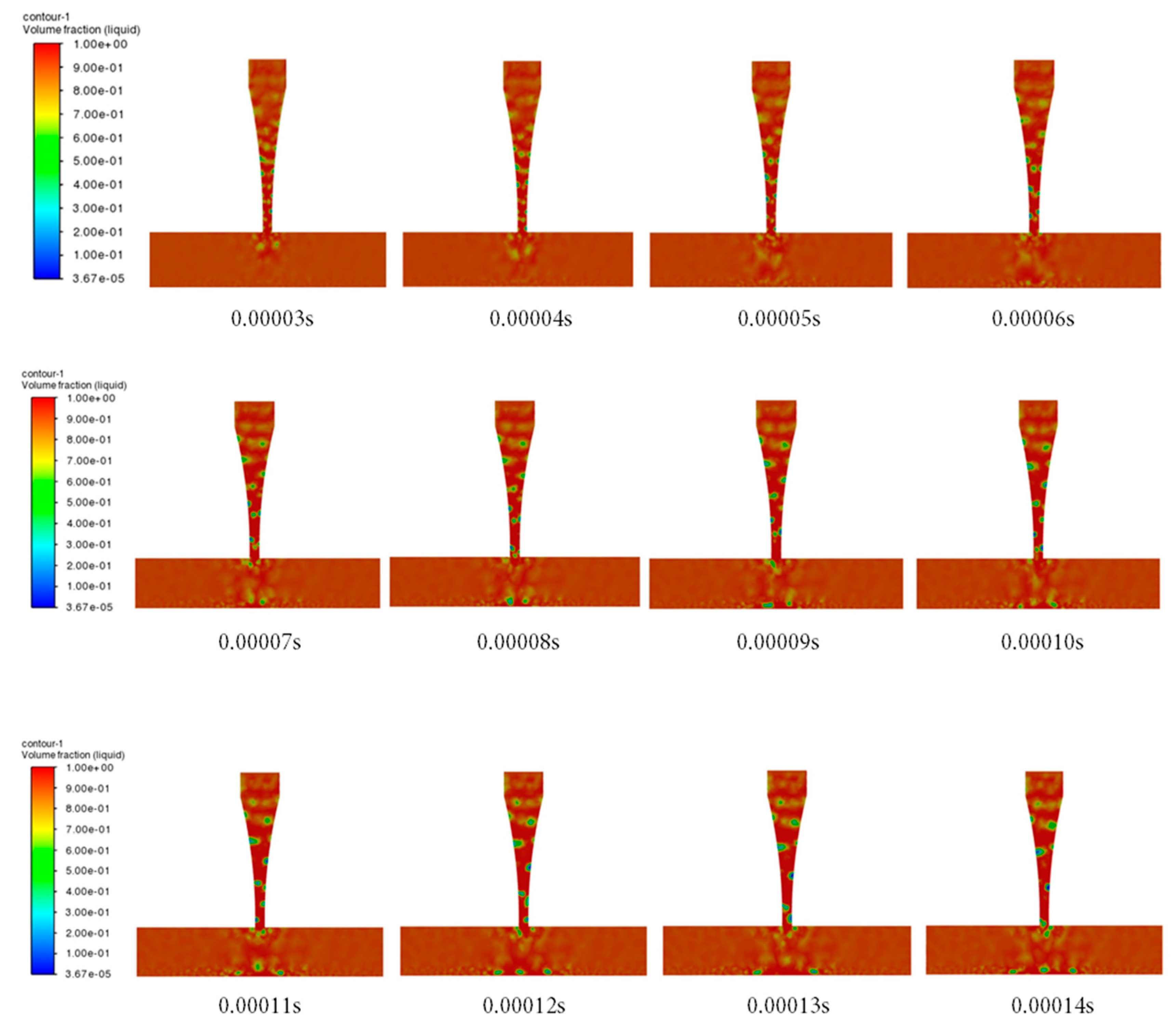
Figure 10: Gas-liquid distribution on nozzle’s cross-section at different times.
5 Optimization of Nozzle Structure
The structural parameters of the nozzle were optimized by analyzing the influence of curvature (R), L/d, D/d, and L1/d of aero nozzle on impact pressure.
As shown in Fig. 11, the nozzle’s curvature affected the pressure at the central point of the targeted surface. At different flow times, the pressure at the central point of the targeted surface varied with the curvatures of the nozzles. With the increase of nozzle curvature, the pressure at the center point of the target surface first increases and then decreases. By comparison, when the nozzle’s curvature was 0.01, the gas-liquid two-phase jet had the maximum impact pressure on the central point of the targeted surface, whereas the high pressure could last for a longer period of time under higher impact pressure. Therefore, the aero nozzle had a better impact on the surface with the curvature of 0.01. A suitable nozzle curvature can generate a greater jet impact force. With the small curvature, the flow was relatively smooth, and the degree of turbulence was not intense, and the energy loss caused by turbulence is relatively small. Small curvature results in a larger radius of curvature, and thus the longer flow path and the greater area and time of contact between the fluid and the nozzle wall lead to an increase in wall friction loss. Pressure energy will be converted into heat energy and dissipated, which made the impact force of the jet insufficient. When the curvature was large, a low-pressure zone was generated due to the centrifugal effect, causing the separation of the boundary layer and forming vortices. The generation and maintenance of vortices consume a significant amount of energy. Meanwhile, the jet impact force reduced because of the consumption of kinetic energy and the divergence and instability of the jet.
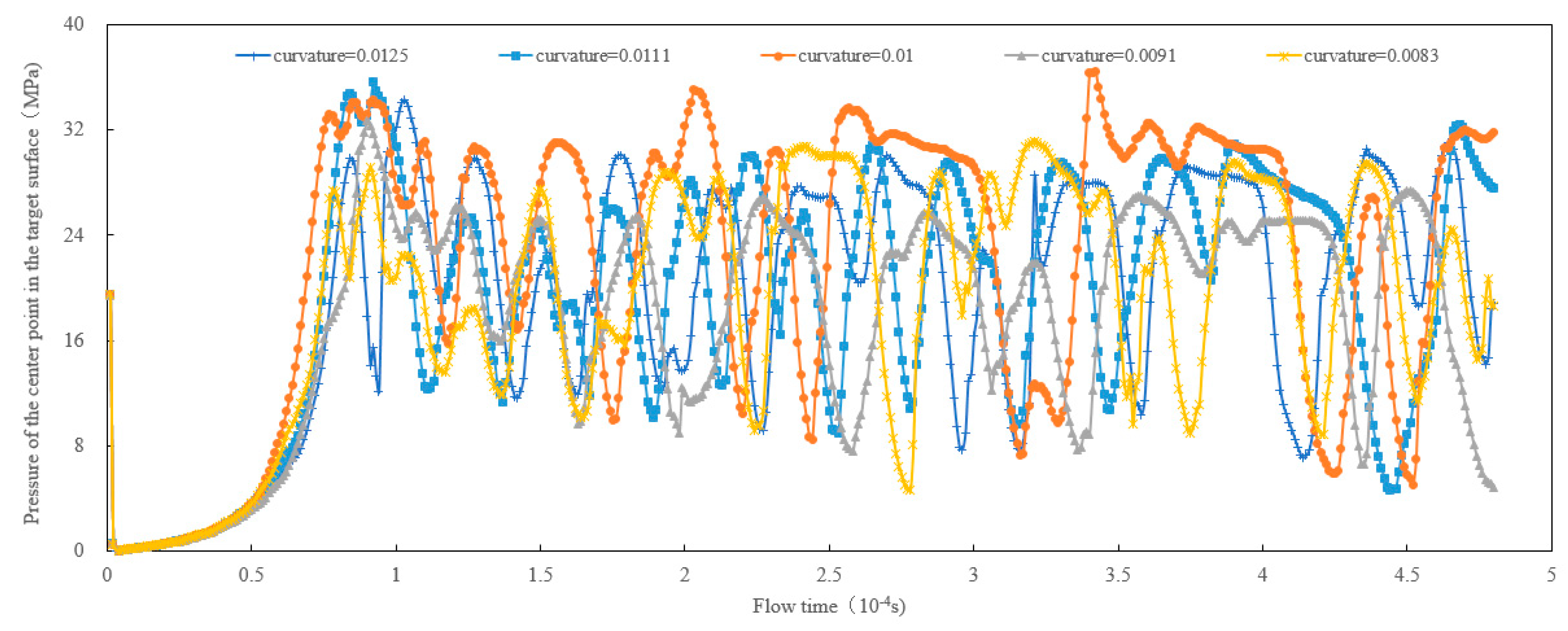
Figure 11: Effect of nozzle’s curvature on the pressure at the central point of targeted surface.
Within the range of nozzle’s aspect ratio of 12–16, the variation of pressure at the central point of the targeted surface with flow time is shown in Fig. 12. Overall, the maximum impact force of the jet on the targeted surface first increased and then decreased with the increase of aspect ratio, whereas the duration under high pressure was also different. When the aspect ratio was 15, the jet generated the maximum pressure on the targeted surface. Within the time period of 0.00016–0.00021 s, higher pressure was maintained and had a pulsating change, indicating that the impact was better. A small aspect ratio caused more drastic changes in the curvature, easily leading to the separation of the flow from the wall. The separation will generate large-scale eddies, consuming a large amount of energy. Meanwhile, the intensity of turbulence and the loss of energy increased, while the turbulent kinetic energy enhanced. As the diffusion angle of the jet increased, the agglomeration of the jet decreased. If the aspect ratio was too high, the flow was smoother, and the degree of separation decreased, while the frictional loss increased with the increase of the length of the shrank segment [49]. The loss of energy will offset the acceleration of the contraction section, and therefore, the jet energy and kinetic energy of the nozzle’s outlet will reduce.
Figure 12: Influence of the aspect ratio of nozzle on pressure at the central point of targeted surface.
Within the range of the nozzle’s shrinkage ratio of 3.5–5.5, the variation of pressure at the central point of the targeted surface with flow time is shown in Fig. 13. With the increase in the shrinkage ratio, the impact force of the jet on the targeted surface first increased and then decreased. When the shrinkage ratio was 4, the impact pressure of the gas-liquid two-phase jet on the central point of the targeted surface was the highest, and the duration was longer under higher pressure, resulting in better impact of the jet. Appropriately increasing the shrinkage ratio can significantly improve the jet velocity and impact force. If the shrinkage ratio was too high, it might lead to flow separation [50], reduce the transfer of effective kinetic energy, and lower the energy utilization efficiency of the jet.
Figure 13: Effect of nozzle’s shrinkage ratio on the pressure at the central point of the targeted surface.
5.4 Ratio of Nozzle’s Inlet Length to Outlet Diameter
The influence of the ratio of the nozzle’s inlet length to outlet diameter on the pressure at the central point of the targeted surface at different times is shown in Fig. 14. As the ratio of the nozzle’s inlet length to outlet diameter increased, the jet impact pressure on the targeted surface first increased and then decreased. When the ratio of the nozzle’s inlet length to outlet diameter was 2.5, the impact pressure of the gas-liquid two-phase jet on the central point of the targeted surface was higher, and its duration was longer under higher impact pressure, indicating that the jet had a better impact. When the inlet section of the nozzle was short, the flow might not have fully developed, resulting in flow distortions or vortices. The increase in energy loss and uneven velocity distribution resulted in flow disorder in the contraction section. Sufficient length of the inlet section can stabilize the flow and reduce the fraction of lateral velocity, thereby reducing the loss of energy [15]. Excessive length of the inlet section will increase frictional loss between the fluid and nozzle wall, and reduce the effective kinetic energy of jet.
Figure 14: Influence of the ratio of length to diameter of the inlet section on the pressure at the central point of the targeted surface.
- (1)The impact of the gas-liquid two-phase jet was better than that of the pure water jet because when the gas-liquid two-phase jet impacted the targeted surface, the irregular pulsation characteristics of pressure were clearly observed. The maximum impact pressure of the jet on the targeted surface varied depending on the nozzle’s structure, and the duration of high pressure also varied with the type of nozzles. By comparison, the impact pressure of the aero nozzle on the targeted surface was 21% higher than that of the conical straight nozzle and 37% higher than that of the conical nozzle. The aero nozzle produced a greater impact pressure on the targeted surface and had a better impact effect.
- (2)High speed occurred at the position from approximately 3 times the nozzle’s diameter inside the nozzle to approximately 2 times the nozzle’s diameter outside of the nozzle. There was no obvious backflow phenomenon in the flow field inside the nozzle. In the external flow field of the nozzle, near the targeted surface, there were significant vertical and tangential velocities. There was a noticeable backflow near the targeted surface of the external flow field, which was beneficial for carrying away debris from cleaning and cutting. When the gas-liquid two-phase jet entered the nozzle, the pressure gradually decreased, and it dropped to a lower value at the outlet of the nozzle. Near the targeted surface, the pressure decreased approximately in a spherical shape with the center of the targeted surface as the spherical center.
- (3)There were obvious bubbles in the nozzle’s contraction section and near the targeted surface with the gas-liquid two-phase jet. The turbulent kinetic energy of the jet inside the nozzle was very small. After the jet was sprayed out of the nozzle, the turbulent kinetic energy increased significantly. There was a local maximum turbulent kinetic energy near the targeted surface, indicating that the level of turbulence of the jet was very high.
- (4)When the gas-liquid two-phase jet entered the nozzle, the gas phase was relatively evenly dispersed in the liquid phase. Later, the concentration of gas phase at local locations began to increase, indicating a tendency for gas cavitation. Bubbles formed near the targeted surface, expanded, became larger, and collapsed under appropriate conditions. The collapse of the bubble generated micro jets, which increased the pressure on the targeted surface.
- (5)The impact pressure of the gas-liquid two-phase jet was the highest with the nozzle’s curvature of 0.01. When the aspect ratio was 15, the jet could exhibit pulsating changes for a longer period of time under higher pressure. When the shrinkage ratio was 4, the jet had a larger impact pressure and a longer period of time under higher pressure. As the ratio of the nozzle’s inlet length to outlet diameter was 2.5, the impact force of the gas-liquid two-phase jet on the targeted surface was higher.
Acknowledgement:
Funding Statement: This research was funded by the National Natural Science Foundation of China, grant number 52204022; Natural Science Foundation of Shandong Province, grant number ZR2022ME152; Youth Innovation and Technology Support Program for Shandong Provincial Universities, grant number 2022KJ066; National Key Research and Development Program of China, grant number 2021YFE0111400; Shandong Provincial Key Research and Development Program (2025TSGCCZZB0419); The Major Special Project for Scientific and Technological Innovation of Dongying City (Science and Technology Development Guidance Plan), grant number 2023ZDJH110.
Author Contributions: The authors confirm their contributions to the paper as follows: study conception and design: Jian Zhao, Xiaodong Dai; simulation: Yuyan Shang, Guoxin Zhang; Analysis and interpretation of results: Fengxia Shi; draft manuscript preparation: Yuan Lu. All authors reviewed the results and approved the final version of the manuscript.
Availability of Data and Materials: The data that support the findings of this study are available from the corresponding author upon reasonable request.
Ethics Approval: Not applicable.
Conflicts of Interest: The authors declare no conflicts of interest to report regarding the present study.
References
1. Shimizu S . Development of water jet technology. J Soc Mech Eng. 1999; 102( 967): 342– 3. doi:10.1299/jsmemag.102.967_342. [Google Scholar] [CrossRef]
2. Kizaki A , Ishii H , Imai T . Waterjet drilling of sealing cement. Procedia Eng. 2017; 191: 869– 72. doi:10.1016/j.proeng.2017.05.255. [Google Scholar] [CrossRef]
3. Sun H , Hu M , Jiang G , Cao G , Ge J , Zhang S , et al. Micro-nano twins appearing in ultrafine-grained Ti–6Al–4V alloy induced by high-pressure water jet technology. Mater Res Express. 2022; 9( 10): 106514. doi:10.1088/2053-1591/ac9818. [Google Scholar] [CrossRef]
4. Aydin G , Kaya S , Karakurt I . Utilization of solid-cutting waste of granite as an alternative abrasive in abrasive waterjet cutting of marble. J Clean Prod. 2017; 159: 241– 7. doi:10.1016/j.jclepro.2017.04.173. [Google Scholar] [CrossRef]
5. Zhao J , Liao H , Xu Y , Shi F , Sun B , Chang F , et al. Experimental and theoretical evaluation of tubing cutting with rotating particle jet in oil and gas borehole operation. Energy. 2023; 282: 128468. doi:10.1016/j.energy.2023.128468. [Google Scholar] [CrossRef]
6. Yang B , Chen J , Li J , Xie W , Wu Q , You D , et al. A numerical study on the design of a diffuser nozzle for pulsed-jet cleaning of cone filter cartridges. Atmosphere. 2025; 16( 4): 379. doi:10.3390/atmos16040379. [Google Scholar] [CrossRef]
7. Goto S , Tsuji H , Onodera I , Watanabe K , Ono K . Cavitation-jet deinking: a new technology for deinking of recovered paper. TAPPI J. 2014; 13( 9): 9– 17. doi:10.32964/tj13.9.9. [Google Scholar] [CrossRef]
8. Guha A , Barron RM , Balachandar R . An experimental and numerical study of water jet cleaning process. J Mater Process Technol. 2011; 211( 4): 610– 8. doi:10.1016/j.jmatprotec.2010.11.017. [Google Scholar] [CrossRef]
9. Annoni M , Arleo F , Malmassari C . CFD aided design and experimental validation of an innovative Air Assisted Pure Water Jet cutting system. J Mater Process Technol. 2014; 214( 8): 1647– 57. doi:10.1016/j.jmatprotec.2014.01.020. [Google Scholar] [CrossRef]
10. Haghbin N , Spelt JK , Papini M . Abrasive waterjet micro-machining of channels in metals: comparison between machining in air and submerged in water. Int J Mach Tools Manuf. 2015; 88: 108– 17. doi:10.1016/j.ijmachtools.2014.09.012. [Google Scholar] [CrossRef]
11. Eddingfield DL , Albrecht M . Effect of an air-injected shroud on the breakup length of a high-velocity waterjet. In: Erosion: prevention and useful applications. West Conshohocken, PA, USA: ASTM; 1979. p. 461– 72. doi:10.1520/stp35812s. [Google Scholar] [CrossRef]
12. Siamas GA , Jiang X , Wrobel LC . Dynamics of annular gas–liquid two-phase swirling jets. Int J Multiph Flow. 2009; 35( 5): 450– 67. doi:10.1016/j.ijmultiphaseflow.2009.02.001. [Google Scholar] [CrossRef]
13. Vijay MM , Zou C , Hu SG , Remisz J , Tavoularis S . A study of the practicality of cavitating water jet. In: Lichtarowicz A , editor. Fluid mechanics and its applications. Berlin/Heidelberg, Germany: Springer; 1992. p. 75– 99. doi:10.1007/978-94-011-2678-6_6. [Google Scholar] [CrossRef]
14. Schadow KC , Gutmark E , Parr DM , Wilson KJ . Selective control of flow coherence in triangular jets. Exp Fluids. 2004; 6( 2): 129– 35. doi:10.1007/BF00196464. [Google Scholar] [CrossRef]
15. Vahedi Tafreshi H , Pourdeyhimi B . The effects of nozzle geometry on waterjet breakup at high Reynolds numbers. Exp Fluids. 2003; 35( 4): 364– 71. doi:10.1007/s00348-003-0685-y. [Google Scholar] [CrossRef]
16. Anantharamaiah N , Vahedi Tafreshi H , Pourdeyhimi B . A study on hydroentangling waterjets and their impact forces. Exp Fluids. 2006; 41( 1): 103– 13. doi:10.1007/s00348-006-0162-5. [Google Scholar] [CrossRef]
17. Yang YS , Zhang JP , Nie SL . Energy loss of nozzles in water jet system. J Mech Eng. 2013; 49( 2): 139– 45. (In Chinese). doi:10.3901/JME.2013.02.139. [Google Scholar] [CrossRef]
18. Jiang T , Huang Z , Li J , Yu C . Numerical investigation of flow resistance in cone-straight nozzle. Geoenergy Sci Eng. 2023; 221: 111252. doi:10.1016/j.petrol.2022.111252. [Google Scholar] [CrossRef]
19. Hu B , He Z , Li C , Deng Y , Guan W , Zhang L , et al. Study of the effect of cavitation flow patterns in diesel injector nozzles on near-field spray atomization characteristics using a LES-VOF method. Int J Multiph Flow. 2024; 174: 104791. doi:10.1016/j.ijmultiphaseflow.2024.104791. [Google Scholar] [CrossRef]
20. Guo CR , Li JB , Li H , Ma RT , Wang H , Zhong H , et al. Comparative of flow field characteristics of cavitation jet nozzles with different structures. Chi Petro Mach. 2024; 52( 12): 8– 16. (In Chinese). doi:10.16082/j.cnki.issn.1001-4578.2024.12.002. [Google Scholar] [CrossRef]
21. Liu X , Jiang W , Cui S , Liu W , Gu Y , Peng T , et al. Investigation of amplification process of heavy oil viscosity reduction device based on jet cavitation using lab experimental and numerical simulation method. Energy Sources Part A Recovery Util Environ Eff. 2025; 47( 1): 8976– 96. doi:10.1080/15567036.2021.1940388. [Google Scholar] [CrossRef]
22. Yu Y , Fan D , Hu Y , Cheng Z , Su Z , Chen S , et al. Characterization of the kinematic features of cavitation bubble-induced jet flow. Int J Heat Mass Transf. 2025; 242: 126782. doi:10.1016/j.ijheatmasstransfer.2025.126782. [Google Scholar] [CrossRef]
23. Xu Y , Tian J , Wang Z , Zhang J , Li S , Yan Y , et al. A comprehensive study on the flow field of cylindrical cavitation nozzle jet under different turbulence models. Ocean Eng. 2025; 315: 119596. doi:10.1016/j.oceaneng.2024.119596. [Google Scholar] [CrossRef]
24. Cao X , Dong M , Bian J . Numerical simulation of a center-water two-phase ejector with non-condensable gas. Energy. 2025; 331: 137080. doi:10.1016/j.energy.2025.137080. [Google Scholar] [CrossRef]
25. Quinn WR , Militzer J . Effects of nonparallel exit flow on round turbulent free jets. Int J Heat Fluid Flow. 1989; 10( 2): 139– 45. doi:10.1016/0142-727X(89)90008-8. [Google Scholar] [CrossRef]
26. Bian J , Ding G , Zhang Y , Cao X , Yu B . Internal mixing mechanism and mixed layer development characteristics of hydrogen recirculation ejector. Renew Energy. 2025; 246: 122896. doi:10.1016/j.renene.2025.122896. [Google Scholar] [CrossRef]
27. Wu Q , Ji G , Zhao J , Sun L , Han D , Liu L , et al. Validation of numerical simulations and experiments on impulse characteristics induced by self-excited oscillation. Sci Rep. 2024; 14( 1): 5505. doi:10.1038/s41598-024-56187-y. [Google Scholar] [CrossRef]
28. Wang L , Wu W , Li X , Fan S , Fang Z . Coupling mechanism of structure–cavitation impact in reflux self-excited oscillating nozzles. Ocean Eng. 2025; 332: 121355. doi:10.1016/j.oceaneng.2025.121355. [Google Scholar] [CrossRef]
29. Ding G , Cao X , Chen J , Zhang Y , Bian J . Impact of the expansion ratio on the properties of hydrogen recirculation ejectors. Appl Energy. 2024; 374: 124026. doi:10.1016/j.apenergy.2024.124026. [Google Scholar] [CrossRef]
30. Liu Y , Chen X , Zhang J , Feng L , Liu H , Hao C . Structural optimization design of ice abrasive water jet nozzle based on multi-objective algorithm. Flow Meas Instrum. 2024; 97: 102586. doi:10.1016/j.flowmeasinst.2024.102586. [Google Scholar] [CrossRef]
31. Bian J , Zhang Y , Liu Y , Gong L , Cao X . Structural optimization of hydrogen recirculation ejector for proton exchange membrane fuel cells considering the boundary layer separation effect. J Clean Prod. 2023; 397: 136535. doi:10.1016/j.jclepro.2023.136535. [Google Scholar] [CrossRef]
32. Shi FX , Zhao J , Zhou Y , Zhang H . Experiments and simulations of surface cleaning for a gas-liquid two-phase jet. Water Sci Technol. 2023; 87( 3): 748– 60. doi:10.2166/wst.2023.029. [Google Scholar] [CrossRef]
33. Zhao J , Zhang G , Xu Y , Wang R , Zhou W , Yang D . Experimental and theoretical evaluation of solid particle erosion in an internal flow passage within a drilling bit. J Petrol Sci Eng. 2018; 160: 582– 96. doi:10.1016/j.petrol.2017.10.068. [Google Scholar] [CrossRef]
34. Liu H , Xu Y , Wang Z , Zhang J , Wang J . Experimental and numerical simulations to examine the mechanism of nozzle geometry affecting cavitation water jets. Geoenergy Sci Eng. 2024; 233: 212511. doi:10.1016/j.geoen.2023.212511. [Google Scholar] [CrossRef]
35. Sun H , Luan F , Feng LL , Zhao P , Chen XY , Zhang J . Structure optimization of high pressure water cleaning nozzle for aluminum alloy car body based on orthogonal experiment. Chin Hydraul Pneum. 2024; 48( 1): 122– 30. (In Chinese). doi:10.11832/j.issn.1000-4858.2024.01.015. [Google Scholar] [CrossRef]
36. Sharma D , Patwardhan A , Ranade V . Effect of turbulent dispersion on hydrodynamic characteristics in a liquid jet ejector. Energy. 2018; 164: 10– 20. doi:10.1016/j.energy.2018.08.171. [Google Scholar] [CrossRef]
37. Ahmed A , Shah A , Qureshi K , Waheed K , Irfan N , Siddique W , et al. Investigation of iodine removal efficiency in a venturi scrubber using mass transfer model for CFD. Prog Nucl Energy. 2020; 121: 103243. doi:10.1016/j.pnucene.2020.103243. [Google Scholar] [CrossRef]
38. Shen SL , Atangana Njock PG , Zhou A . Influence of nozzle structure on effectiveness of jet grouting operations and its optimal design. Geoenergy Sci Eng. 2023; 226: 211788. doi:10.1016/j.geoen.2023.211788. [Google Scholar] [CrossRef]
39. Jiang T , Huang Z , Li J , Zhou Y , Xiong C . Experimental investigation of internal and external flow fields of jetting nozzles with different structures. J Petrol Sci Eng. 2022; 217: 110891. doi:10.1016/j.petrol.2022.110891. [Google Scholar] [CrossRef]
40. Cheng MZ , Cai Y , Chen LH , Li YF . Structure design and flow-field simulation of high-pressure water jet nozzle based on CFD. J Mach Des. 2023; 40( 12): 79– 85. (In Chinese). doi:10.13841/j.cnki.jxsj.2023.12.025. [Google Scholar] [CrossRef]
41. Minsier V , De Wilde J , Proost J . Simulation of the effect of viscosity on jet penetration into a single cavitating bubble. J Appl Phys. 2009; 106( 8): 084906. doi:10.1063/1.3243288. [Google Scholar] [CrossRef]
42. van Wijngaarden L . Mechanics of collapsing cavitation bubbles. Ultrason Sonochem. 2016; 29: 524– 7. doi:10.1016/j.ultsonch.2015.04.006. [Google Scholar] [CrossRef]
43. Abbassi W , Besbes S , Ben Aissia H , Champagne JY . Study of the rise of a single/multiple bubbles in quiescent liquids using the VOF method. J Braz Soc Mech Sci Eng. 2019; 41( 6): 272. doi:10.1007/s40430-019-1759-y. [Google Scholar] [CrossRef]
44. Shi FX , Zhao J , Sun XG , Yin HL . Numerical simulation of surface cleaning flow field for gas-liquid two-phase jet. J Cent South Univ Sci Technol. 2021; 52( 3): 960– 70. (In Chinese). doi:10.11817/j.issn.1672-7207.2021.03.027. [Google Scholar] [CrossRef]
45. Dehkhoda S , Hood M . The internal failure of rock samples subjected to pulsed water jet impacts. Int J Rock Mech Min Sci. 2014; 66: 91– 6. doi:10.1016/j.ijrmms.2013.12.021. [Google Scholar] [CrossRef]
46. Chen X , He Z , Ao X , Zhan L . Analysis of the effect of blade inclination angle on the performance of oblique spiral cavitating nozzle. Int J Multiph Flow. 2025; 185: 105141. doi:10.1016/j.ijmultiphaseflow.2025.105141. [Google Scholar] [CrossRef]
47. Tao A , Li C , Jie Z , Zhang Y , Chen X , Liu W . Optimization of a perforator nozzle based on the constant velocity of jet core. Fluid Dyn Mater Process. 2025; 21( 3): 645– 56. doi:10.32604/fdmp.2025.059545. [Google Scholar] [CrossRef]
48. Ida M , Naoe T , Futakawa M . Direct observation and theoretical study of cavitation bubbles in liquid mercury. Phys Rev E Stat Nonlin Soft Matter Phys. 2007; 75( 4 Pt 2): 046304. doi:10.1103/PhysRevE.75.046304. [Google Scholar] [CrossRef]
49. Li J , Li D , Li T . Progress in the understanding and modeling of cavitation and related applications. Fluid Dyn Mater Process. 2025; 21( 3): 445– 70. doi:10.32604/fdmp.2025.062337. [Google Scholar] [CrossRef]
50. Brouillette M . The Richtmyer-meshkov instability. Annu Rev Fluid Mech. 2002; 34: 445– 68. doi:10.1146/annurev.fluid.34.090101.162238. [Google Scholar] [CrossRef]
Cite This Article
 Copyright © 2025 The Author(s). Published by Tech Science Press.
This work is licensed under a Creative Commons Attribution 4.0 International License , which permits unrestricted use, distribution, and reproduction in any medium, provided the original work is properly cited.
 Downloads
 Citation Tools