
 Submit a Paper
 Propose a Special lssue
 Open Access
ARTICLE

4D Evolution of In-Situ Stress and Fracturing Timing Optimization in Shale Gas Wells
1 Shale Gas Research Institute, PetroChina Southwest Oil and Gas field Company, Chengdu, 610051, China
2 State Key Laboratory of Oil and Gas Reservoir Geology and Exploitation, Southwest Petroleum University, Chengdu, 610500, China
3 Engineering Technology Department, PetroChina Southwest Oil and Gas Field Company, Chengdu, 610056, China
* Corresponding Author: Huiying Tang. Email:
Fluid Dynamics & Materials Processing 2025, 21(5), 1201-1219. https://doi.org/10.32604/fdmp.2025.060311
Received 29 October 2024; Accepted 17 February 2025; Issue published 30 May 2025
 View Full Text
 Download PDF
Abstract
Over more than a decade of development, medium to deep shale gas reservoirs have faced rapid production declines, making sustained output challenging. To harness remaining reserves effectively, advanced fracturing techniques such as infill drilling are essential. This study develops a complex fracture network model for dual horizontal wells and a four-dimensional in-situ stress evolution model, grounded in elastic porous media theory. These models simulate and analyze the evolution of formation pore pressure and in-situ stress during production. The investigation focuses on the influence of infill well fracturing timing on fracture propagation patterns, individual well productivity, and the overall productivity of well clusters. The findings reveal that, at infill well locations, the maximum horizontal principal stress undergoes the most significant reduction, while changes in the minimum horizontal principal stress and vertical stress remain minimal. The horizontal stress surrounding the infill well may reorient, potentially transitioning the stress regime from strike-slip to normal faulting. Delays in infill well fracturing increase lateral fracture deflection and diminish fracture propagation between wells. Considering the stable production phase and cumulative gas output of the well group, the study identifies an optimal timing for infill fracturing. Notably, larger well spacing shifts the optimal timing to a later stage.Keywords
Shale gas is a significant unconventional energy source, but its development process faces challenges, such as low reservoir porosity and permeability, which contribute to a rapid decline in gas well production, in addition to the high costs involved in mitigating these issues [1–3]. It is widely believed both domestically and internationally that encrypted well technology is key to improving shale gas recovery rates [4,5]. In North America, the primary methods for enhancing recovery rates include the use of optimized techniques such as well pattern encryption and three-dimensional development to strengthen the control of reserves by the well network [6–8]; Secondly, by optimizing development policies, improving fracturing techniques, and enhancing drainage and gas extraction processes, the production of individual wells is increased [9]. Combining engineering techniques and economic analysis, single-well EUR (Estimated Ultimate Recovery) and block recovery rates are used as technical indicators, while NPV (Net Present Value) serves as the economic indicator. Well spacing is adjusted in real-time based on changes in gas prices and costs to continuously improve block recovery rates, thus achieving maximum returns [10,11]. Currently, the recommended well spacing for the Haynesville and Marcellus shale gas fields is 200–300 m, respectively [12–14]. Due to limited experience, the initial well spacing was large initially. In certain regions, shale gas wells typically had a spacing of 400–500 m, which led to suboptimal utilization of horizontal wells. Following optimization and adjustments, a denser well spacing of 300 m has been recommended [15]. Additionally, pilot experiments on the optimization and control of “fracture-controlled reserves” technology have significantly enhanced both primary and secondary fracturing stimulation in tight oil and gas reservoirs [16]. To fully tap into the untapped reserves of the reservoir and enhance regional production capacity, it is urgent to deploy a large number of infill wells.
The key to research the well pattern of shale gas infill wells lies in coordinating the spacing of the well network with the matching relationship of volumetric fracturing. Special attention needs to be given to the simulation of hydraulic fracture propagation under the multi-physical field coupling of in-situ stress evolution during long-term injection and production in oil and gas reservoirs. During the initial hydraulic fracturing operations, the formation is in its original state, and fracture propagation on both sides of the wellbore is relatively uniform. However, as development progresses, reservoir pressure and in-situ stress conditions change continuously, resulting in significant differences in fracture propagation between old wells and infill wells, which in turn affects the deployment of later infill wells. Kumar et al. conducted a systematic study on the model of the parent well’s depletion impact on the fracturing and productivity of infill wells. The results show that when well spacing is close, the infill wells are affected by the depletion zone of the parent well, leading to asymmetric hydraulic fracture propagation [8,17–20]. This phenomenon has been validated through field well testing, tracer testing, and microseismic monitoring of fracturing [21−23]. The reasons for this are twofold: Firstly, the pressure sink formed around the parent well directs the fracturing towards the parent well when fracturing the child well. Secondly, the depletion of pore pressure around the parent well alters the magnitude and direction of the local principal stress, leading to a redistribution of stress [24]. Gupta et al., through a case study of two shale gas platforms, described an integrated approach. This study revealed the close relationship between reservoir depletion behavior and the spatiotemporal distribution of stress and similarly indicated that reservoir depletion could have a negative impact on the fracture propagation of child wells [25]. This phenomenon is influenced by various factors, including well spacing, the production level of existing wells, formation properties, in-situ stress conditions, the development of natural fractures, the timing of fracturing in existing wells, the complexity of hydraulic fractures, the type of fracturing fluid, and operational parameters. Therefore, studying the fracture propagation patterns of existing wells and infill wells requires a comprehensive consideration of multiple factors [26–28].
Rezaei developed a novel transient fully coupled poroelastic displacement discontinuity model to study the impact of factors such as injection pressure, well spacing, the spacing of existing fractures, and the difference between maximum and minimum horizontal stresses on the propagation of hydraulic fractures in nearby infill wells [29]. Rezaei et al. used global sensitivity analysis based on Sobol techniques to identify the most important rock and design parameters affecting pore pressure and stress changes during production. They found that mobility (i.e., the ratio of rock permeability to fluid viscosity) and production pressure are the primary parameters influencing pore pressure and stress changes. Additionally, fracture half-length and fracture spacing also contribute to stress changes at the fracture gaps [30,31]. Given that production time, formation conditions, and the interactions between existing wells and infill wells are dynamically changing, selecting the appropriate timing for infill well fracturing is particularly critical. Current studies rarely conduct systematic research on the spatial and temporal evolution characteristics of the magnitude and direction of three principal stresses between wells, as well as the state of ground stress, when comprehensively considering this complex process.
To further explore the fracturing design and development strategy for infill wells in medium to deep shale gas reservoirs, this paper selects a shale gas infill well platform in southern Sichuan as the research subject. Firstly, we established an integrated model that includes a three-dimensional geological model, a natural fracture model, and a geomechanical model to reconstruct the heterogeneous stress field and analyze the inter-well stress state after the production of existing wells. Based on these models and analyses, we further simulated and explored the fracturing fracture propagation patterns of infill wells and the development effectiveness of the infill well groups. Through this series of studies, this paper aims to optimize the timing of fracturing for infill wells in shale gas reservoirs and provide theoretical guidance for the fracturing design and reservoir development of mid-to-deep shale gas infill wells. These research outcomes not only aid in optimizing the fracturing design of infill wells but also enhance the overall development efficiency of the gas reservoir.
The marine shale is the most realistic domain for large-scale development and sustained increase of shale gas production [32]. The target shale gas field in this study has proven geological reserves exceeding 400 billion cubic meters, and by 2020, it had achieved an annual production capacity of 5 billion cubic meters. By the end of 2022, the highest tested production from horizontal wells in the target shale gas field reached 730,000 cubic meters per day, with the estimated ultimate recovery (EUR) per well ranging from 78 to 135 million cubic meters. With ongoing development, the study area has essentially achieved full initial well network coverage for horizontal shale gas wells. However, due to unclear geological understanding and immature construction techniques in the early stages, some areas experienced inadequate reservoir stimulation due to large well spacing, low transformation intensity, and large cluster spacing. To enhance overall reserve utilization, it is necessary to deploy a denser well network.
The method of four-dimensional in-situ stress analysis used in this study is based on a three-dimensional geological model. It simulates the entire process, including parent well fracturing, production, infill well fracturing, and subsequent production. For fracturing simulation, an Unconventional Fracture Model (UFM) based on the boundary element method is used. This model is embedded into the geological model to create an unstructured grid. The Intersect simulator is then employed to simulate the production dynamics of horizontal wells in shale gas reservoirs. The results of pore pressure changes from the reservoir numerical simulation are mapped onto the geo-mechanical model. A geo-mechanical simulator, Visage, which is based on the finite element algorithm, is used to simulate the four-dimensional in-situ stress field. This approach analyzes the changes in pore pressure and stress at different stages of the reservoir, providing technical support for well spacing optimization in new platform wells.
2.1.1 Fracture Propagation Model
The geometry of hydraulic fractures plays a crucial role in the assessment of development areas in shale reservoirs. One of the objectives of this work is to evaluate the impact of reservoir depletion between wells, which requires a description of fracture propagation geometry. This paper utilizes the Unconventional Fracture Model (UFM) proposed by Weng et al. [33–35], commonly used for simulating complex fracture networks. Its main features are as follows:
1. The model assumptions are based on elastic deformation and material balance.
2. It can simulate fracture initiation between different perforation clusters within a single fracturing stage.
3. It models the transport process of proppant within fractures and predicts the dynamic distribution of fluid and proppant.
4. It considers interactions with natural fractures to generate non-planar hydraulic fracture geometries.
5. The calculations include stress shadow effects generated within and between fracturing stages.
The saturated rock mass can be regarded as a continuous porous medium composed of a rock skeleton phase and a fluid phase. Assuming small deformation conditions, the stress equilibrium equations can be derived using the theory of elastic porous media. By applying Newton’s second law to a unit mass of saturated porous medium (neglecting the inertial forces of the rock mass), the mechanical governing equation of the system can be expressed as:
where the tensile stress is defined as positive;
where ν is the flow rate; μ is fluid viscosity; k is permeability. The total stress can then be calculated with the pore pressure and effective stress induced by skeleton strains:
where b is the Biot coefficient and C is the stiffness matrix of the rock skeleton. By substituting Eqs. (2)–(4) into (1), a complete mechanical equilibrium expression of saturated rock mass can be obtained:
where the effective stress acting on the rock skeleton is represented by
Combined with Eqs. (5) and (6) to solve the displacement and strain of rock, the total stress and effective stress can be obtained.
The dual horizontal well group model and the ground stress model are shown in Fig. 1. The model parameters are set based on the development parameters of the horizontal well group in the target well area, as shown in Table 1.
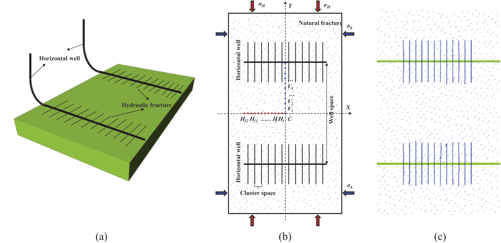
Figure 1: (a) Diagram of the model. In (b) point Hi represents the stress recording points along the X-axis (
In the basic case, the initial maximum horizontal principal stress direction is parallel to the Y-axis in Fig. 1. The parent well is located in the middle of the reservoir, with a basic well spacing of 500 m and a fracture spacing of 30 m. The reservoir computational domain has a length of 1000 m and a width of 600 m, with a horizontal grid spacing of 2 m, a total reservoir thickness of 90 m, and a total of 2,250,000 grid cells. The fracturing simulation considers natural fractures, with the fracture propagation range being 30 m in the middle of the model and a height of 30 m, as shown in Fig. 1c for the parent well fracture geometry. The numerical simulation includes two horizontal wells, both using constant production rates initially, followed by constant bottom-hole pressure production with a bottom-hole pressure of 10 MPa, to obtain the evolution pattern of the ground stress field during the pore pressure reduction process.
During the production process of the parent well, changes in formation conditions can affect the complex fractures formed by hydraulic fracturing. The interference between infill wells and old wells also dynamically changes with the degree of reservoir depletion and the current spacing of the parent wells. To optimize the fracturing timing of the infill wells and maximize the production capacity of the infill well group, the spatiotemporal evolution characteristics of the inter-well stress field in the development of tight oil reservoirs with horizontal well groups under different production times and well spacings of the parent wells are explained.
3.1 The Production Time of the Parent Well
3.1.1 Evolution of Production-Induced Stress
Figs. 2–4 show the distribution of pore pressure and horizontal induced stress (Syy and Sxx) at four different production times for the well groups, with the selected times being initial, and after 1, 3, and 10 years of production. The results indicate that during production, the pore pressure experiences the greatest decrease, and the horizontal stress also reduces. As the pore pressure drops, the magnitude of the horizontal induced stress continues to change, significantly decreasing within the fracture range, with the changes within the fractures being greater than those between the fractures.
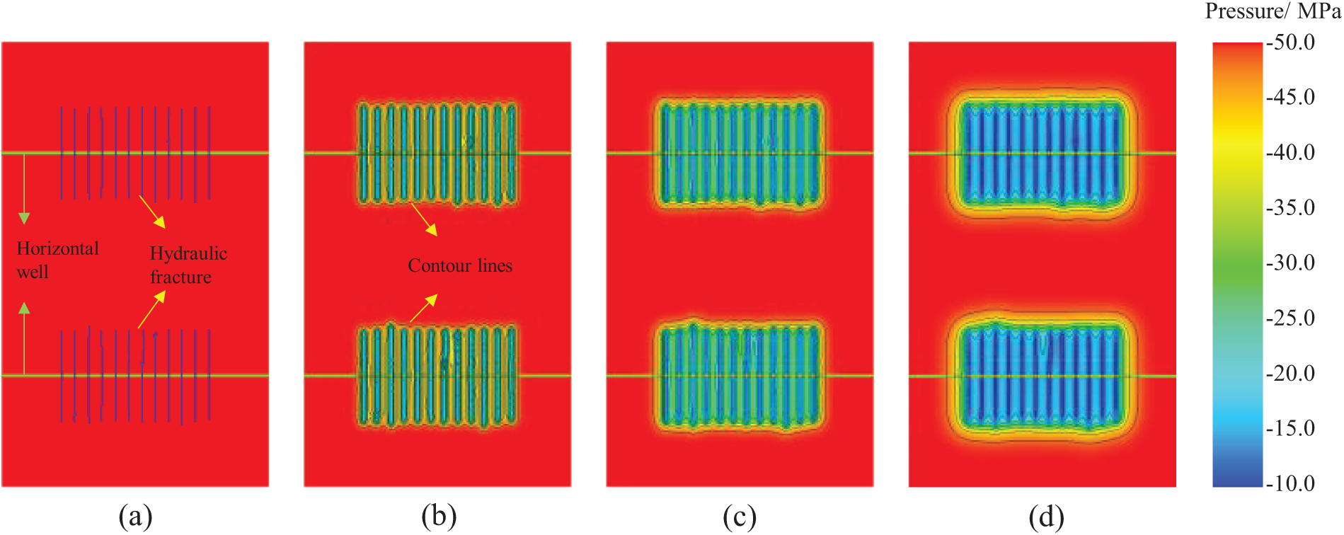
Figure 2: Pore pressure distribution during the production process, (a–d) represent the production times of 0, 1, 3, and 10 years, respectively
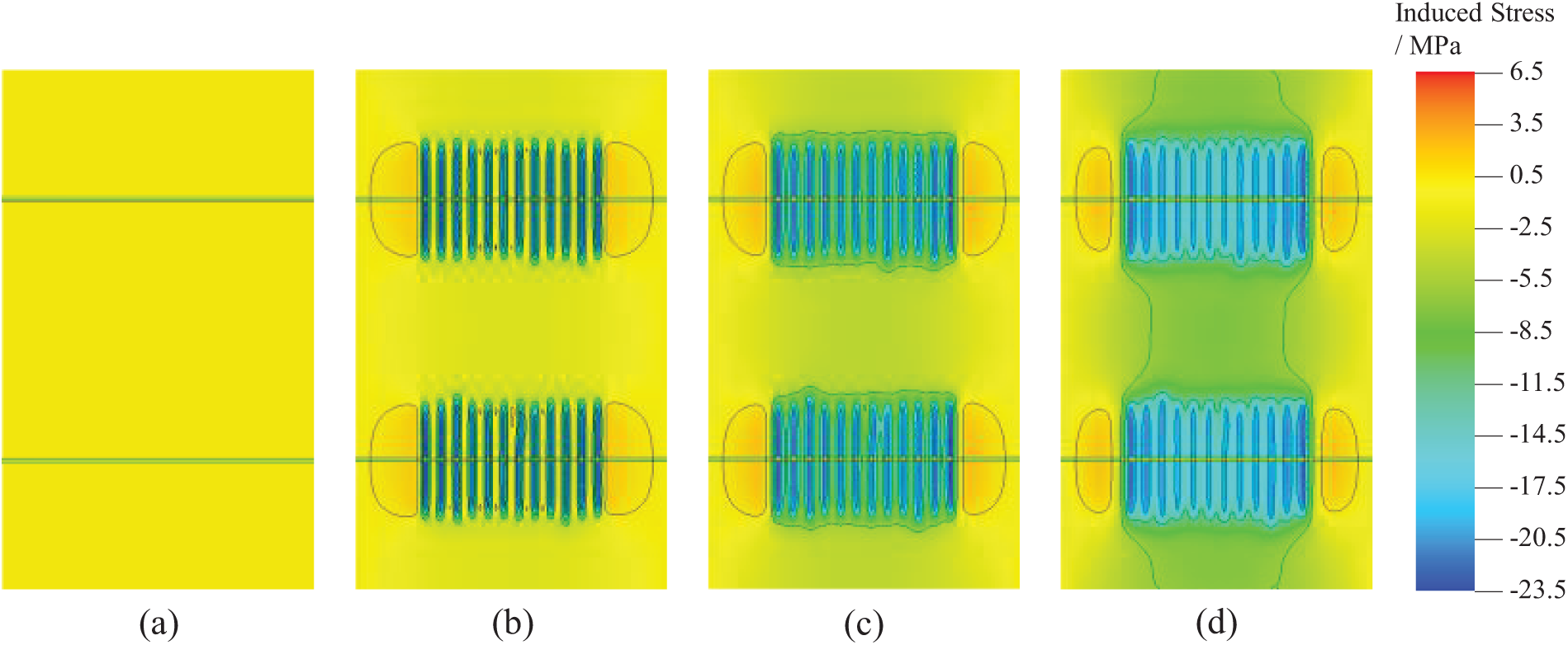
Figure 3: Induced stress distribution in the Y direction during the production process, (a–d) represent the production times of 0, 1, 3, and 10 years, respectively
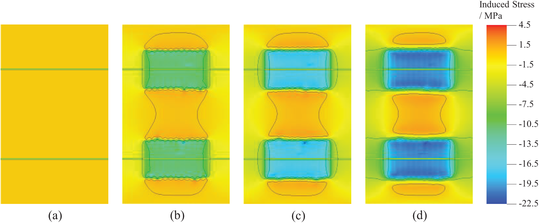
Figure 4: Induced stress distribution in the X direction during the production process, with (a–d) representing production times of 0, 1, 3, and 10 years, respectively
3.1.2 Stress Evolution Law (Interwell X Direction)
The aforementioned simulation results indicate that in the untouched area between wells, the horizontal induced stress along the well trajectory direction is shown. Fig. 5 illustrates the variation curves of the three principal stresses (σH, σh, σV) and the horizontal stress difference (σH–σh) between points H12 and C at the center between wells over production time. As the production time of the parent well increases, the evolution amplitude of σH is greater than that of σh, and σh rises in the middle of the fractured section. The closer σH is to point C, the greater the decrease, significantly reducing the horizontal stress difference in the middle of the well group, as shown in Fig. 5c. The most likely location for stress reversal is at point C, where the stress difference decreases from 10 to 1.5 MPa. Under the current geological model conditions and well spacing, stress reversal does not occur. The vertical stress σV changes the slowest in this process, decreasing by only 0.08 to 0.4 MPa, as shown in Fig. 5d.
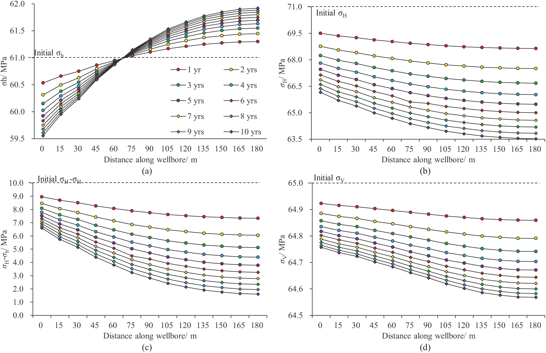
Figure 5: The relationship curves between time and the three principal stresses and horizontal stress difference in the inter-well (X direction) are as follows: (a) X direction stress; (b) Y direction stress; (c) horizontal stress difference; (d) vertical stress
To study the variation of horizontal in-situ stress difference under current conditions, the distribution of in-situ stress difference in the well group model was calculated. Fig. 6a shows the initial in-situ stress difference distribution, which is uniformly 10 MPa. From Fig. 6b, it can be seen that significant changes in in-situ stress difference occur near the fracture zone. The maximum horizontal stress difference increases to 24 MPa, while the minimum decreases to −4 MPa.
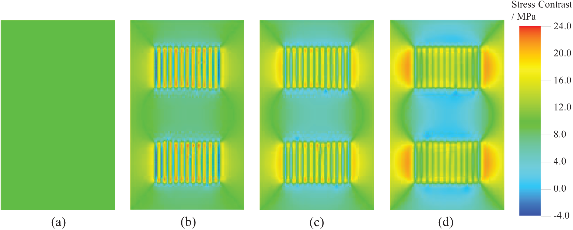
Figure 6: Distribution of horizontal stress difference during production: (a–d) represent production times at 0, 1, 3, and 10 years, respectively
In order to determine the distribution of the differential in-situ stress in the reservoir during the production process, it is divided into four regions based on the magnitude of change in the stress difference: (1) Regions where the change is less than 10% are designated as transition zones; (2) Regions where the in-situ stress difference decreases by more than 10% are designated as stress reduction zones; (3) Regions where the in-situ stress difference increases by more than 10% are designated as stress increase zones; (4) Regions where the stress difference decreases to below zero within the stress reduction zone are designated as stress reversal zones. As shown in Fig. 7, Region 1 represents the transition zone, Region 2 represents the stress reduction zone, Region 3 represents the stress increase zone, and Region 4 represents the stress reversal zone.
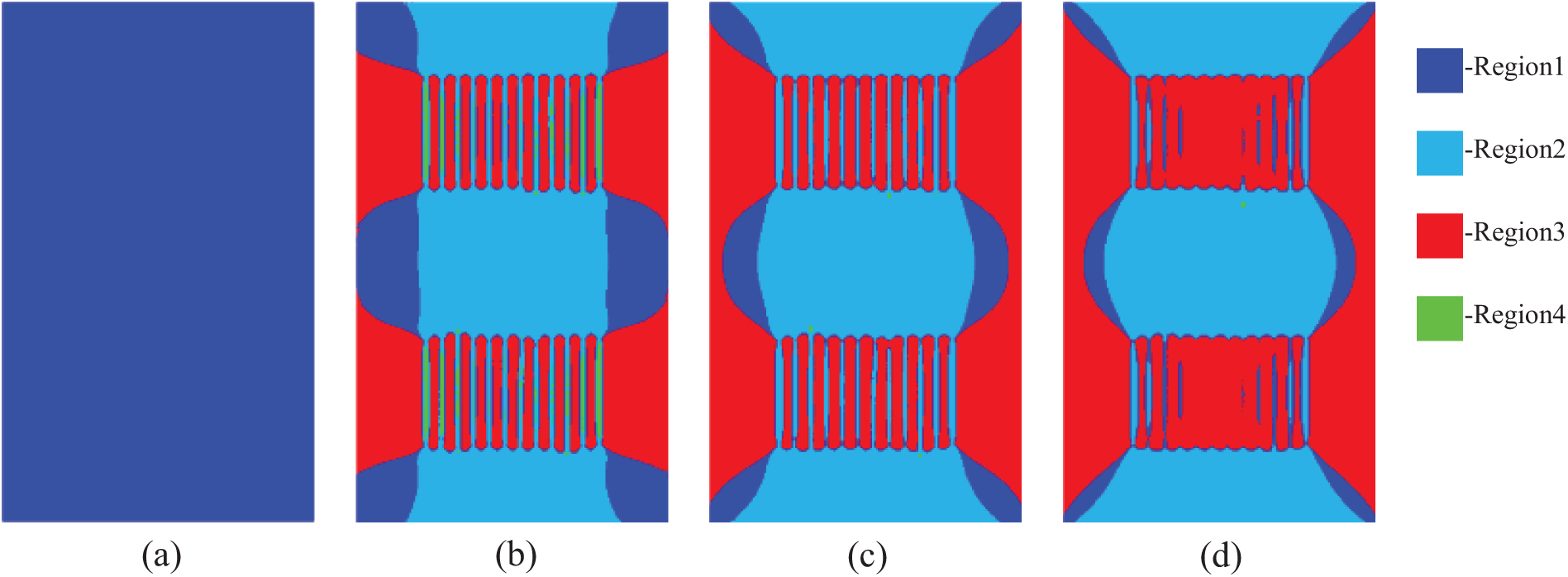
Figure 7: Differential horizontal stress zones during the production process, (a–d) represent production times at 0, 1, 3, and 10 years, respectively
According to our zoning rules, the area of increased stress difference during production is distributed in a direction perpendicular to the fractures, appearing almost symmetrically. The area of decreased stress difference is distributed along the direction of the fractures. As production progresses, the range of the transition zone gradually decreases, while the corresponding areas of increased and decreased stress differences expand. However, the stress difference distribution does not change monotonically with production. As shown in Fig. 7b, after 1 year of production, stress reversal occurred within the fractures at both ends, and in subsequent production, it gradually transitioned to a stress reduction area, as seen in Fig. 7c,d.
3.1.3 Stress Evolution Law (Interwell Y Direction)
The selected recording point V is located at the midline between the 6th and 7th clusters of fractures in the parent well. Fig. 8 shows the three-directional stress statistics along the line from point V13 to C, divided into the fracture-controlled area of the parent well and the undeveloped area. Under the current well spacing conditions, point V13 is located at the parent wellbore, and point V8 is at the boundary of the parent well fracture. As shown in Fig. 8a, there is an abrupt change in σh over a 40 m range from the fracture boundary to the undeveloped area. The longer the production time, the greater the change in horizontal stress. σh decreases rapidly within the parent well fracture control area, while it slightly increases in the undeveloped area. The overall decrease in σH is less than that of σh, and from the wellbore to the infill well position, it first increases and then decreases beyond the fracture tip. The overall horizontal stress difference in the infill well control area is smaller than in the parent well. After production, the changes in vertical stress are complex and large, with increases between fractures and decreases within fractures. The change magnitude of induced stress in the Z direction (Szz) does not monotonically increase with production time. As shown in Fig. 9b, the induced stress change magnitude after 1 year of production is greater than at other times; combined with the statistical results in Fig. 8d, the vertical stress from the parent wellbore to its fracture boundary gradually decreases, shows an upward trend at the transition point, and monotonically decreases beyond approximately 40 m from the fracture tip.
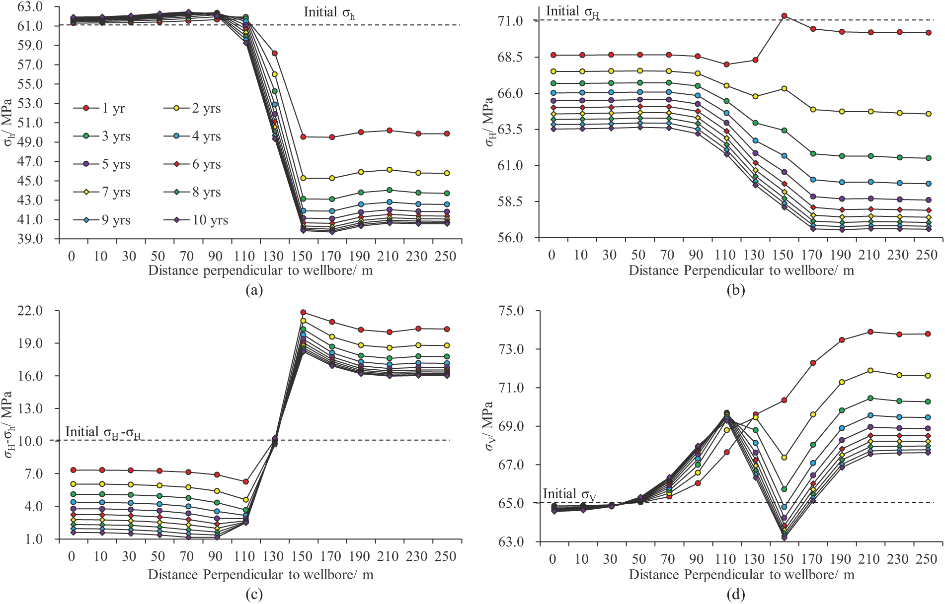
Figure 8: The relationship curves between inter-well (Y direction) triaxial principal stresses and horizontal stress difference with time: (a) X direction stress; (b) Y direction stress; (c) horizontal stress difference; (d) vertical stress
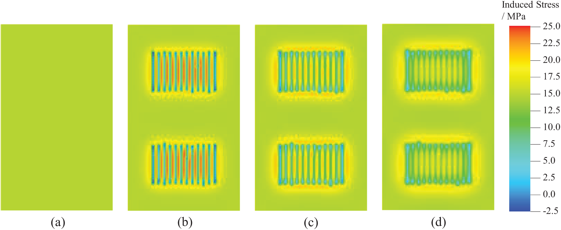
Figure 9: Distribution of induced stress in the Z direction during production, with (a)–(d) representing production times of 0, 1, 3, and 10 years, respectively
3.2.1 Effect of Well Spacing on Induced Stress Evolution
The actual well spacing implemented on the H3 platform is between 450 and 500 m. The selected well spacings are 400, 450, 500, and 600 m. The pore pressure distribution after 10 year’s production with different well spacings is shown in Fig. 10. Fig. 11 demonstrates the induced stress in the X, Y, and Z directions. The reduction in pore pressure within the fracture-controlled area of the parent well is similar with different well spacings. However, the evolution of induced stress in three directions shows some differences. For example, in the inter-well area, changes of well spacing show little reduction in pore fluid pressure, with the decrease of values being less than 0.1 MPa. Though the pore pressure changes quite small, the stresses show more obvious changes, especially in the X and Y directions. The induced stress in the X direction increases from 0.4 to 0.6 MPa while the stresses in Y direction decreases around 0.2 MPa. The changes of stress become more significant when smaller well spacing is used. The changes of stress in Z direction is much smaller than other directions, especially in the inter-well area.
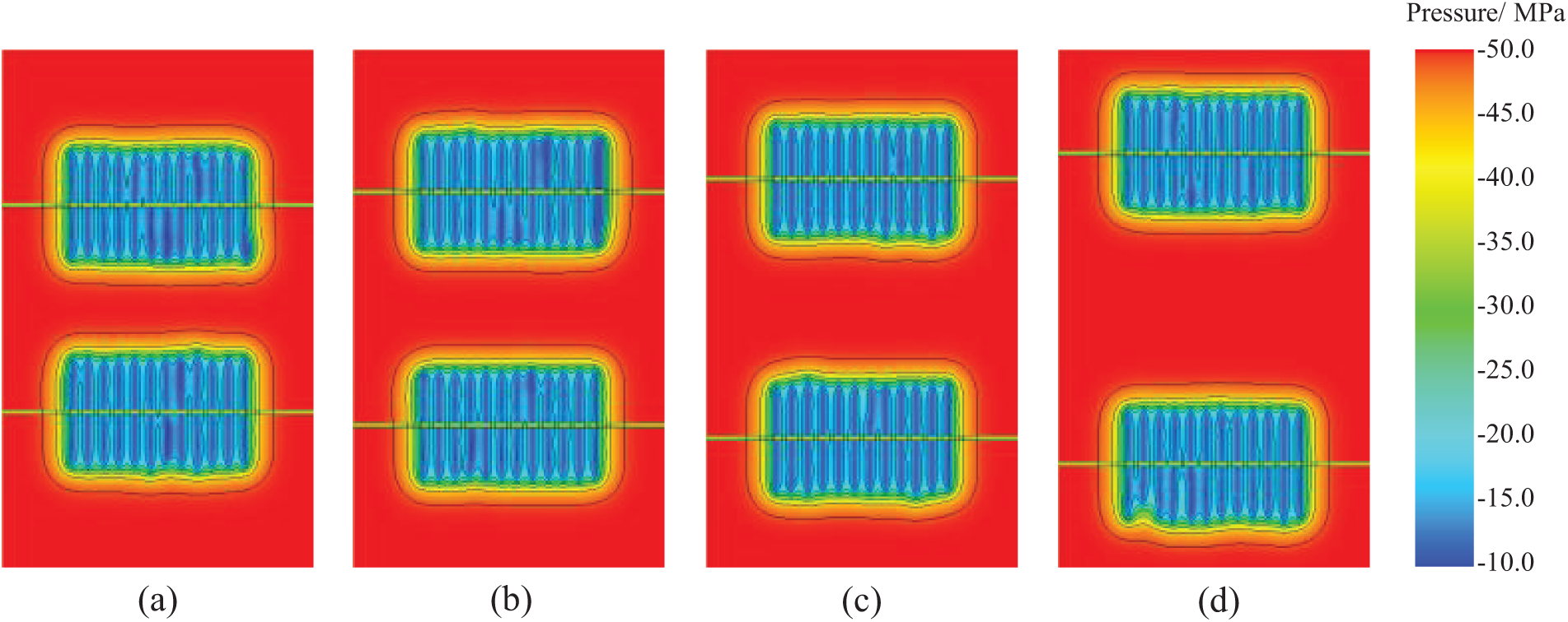
Figure 10: Pore pressure distribution under different well spacing over 10 years of production: (a) 400 m; (b) 450 m; (c) 500 m; (d) 600 m
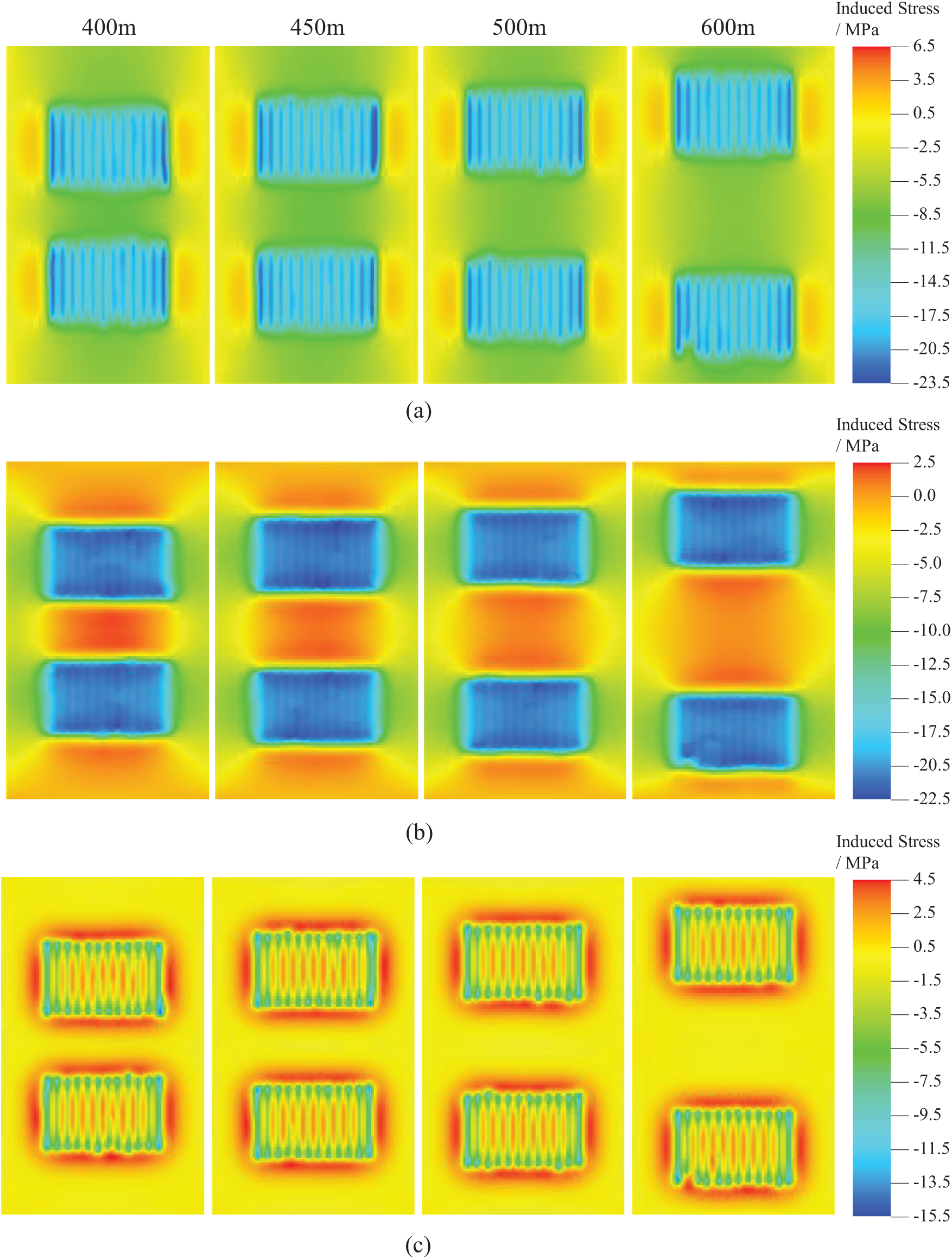
Figure 11: Induced stress distribution in three directions after 10 years of production for the parent well at various well spacings: (a) Y direction; (b) X direction; (c) Z direction
3.2.2 Stress Evolution Law between Parent Wells
For the inter-well region, Fig. 12 shows the variation curves of the three principal stresses and horizontal stress difference from point H12 to point C at the center between wells, after 10 years of production from the parent well at various well spacings. Increasing the well spacing significantly reduces the decline in horizontal principal stress, which can effectively mitigate the degree of deviation in the direction of horizontal principal stress between wells. As shown in Figs. 12c and 13, when the well spacing is 400 m, the horizontal principal stress between the infill well location H2 and point C reverses in the 10th year of production. However, when the well spacing increases to 450 m, under the simulation conditions in this study, the direction of horizontal principal stress in the infill well region does not reverse.
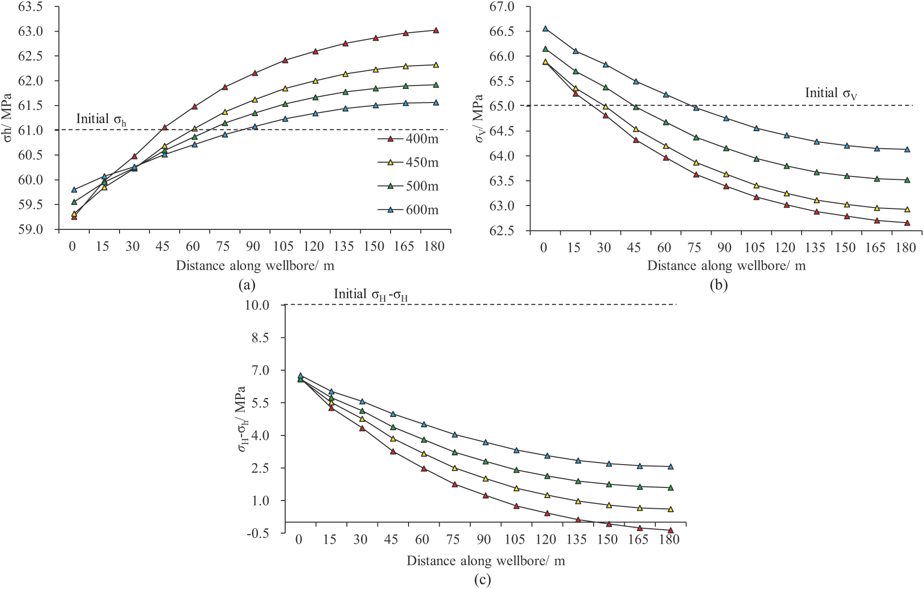
Figure 12: Curves of the relationship between well spacing and triaxial principal stresses as well as horizontal stress contrast in the X direction: (a) Stress in the X direction; (b) Vertical stress; (c) Horizontal stress contrast
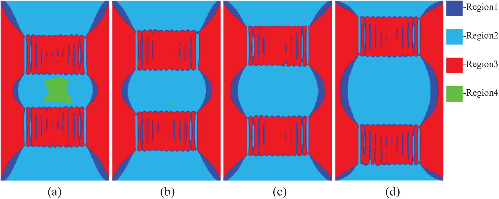
Figure 13: Horizontal stress contrast over 10 years of production at various well spacings for the parent well: (a) 400 m; (b) 450 m; (c) 500 m; (d) 600 m
4 Optimization of Fracturing Timing for Infill Wells
Based on the prediction of ground stress evolution in Section 3, the optimal timing for infill well fracturing is selected. During the development of shale gas reservoirs, the formation pore pressure and stress conditions change over different periods, affecting the propagation pattern of hydraulic fractures and the productivity performance of infill and adjacent wells. Therefore, when selecting the timing for infill well fracturing, it is important to comprehensively consider the propagation of hydraulic fractures, the fracturing stimulation of the infill well, and the impact on the overall productivity of the well group.
4.1 Fracture Geometry of Infill Well
The same fracturing plan as the parent well was adopted. Taking a parent well spacing of 500 m as an example, the fracture geometry of infill wells was compared after 1, 3, 5, 7, and 10 years of production (Fig. 14). From the figure, it can be seen that after 1 year of production, the hydraulic fractures in each cluster of the infill wells are relatively uniform, with no obvious deviation. However, as the timing of fracturing is delayed, the fracture network shows a noticeable deviation at the front end near the old well. At the same time, the differences in the propagation of fractures in each cluster within the fracturing section also gradually increase. This indicates that over time, changes in formation stress and pore pressure have a significant impact on the formation and propagation of fractures.
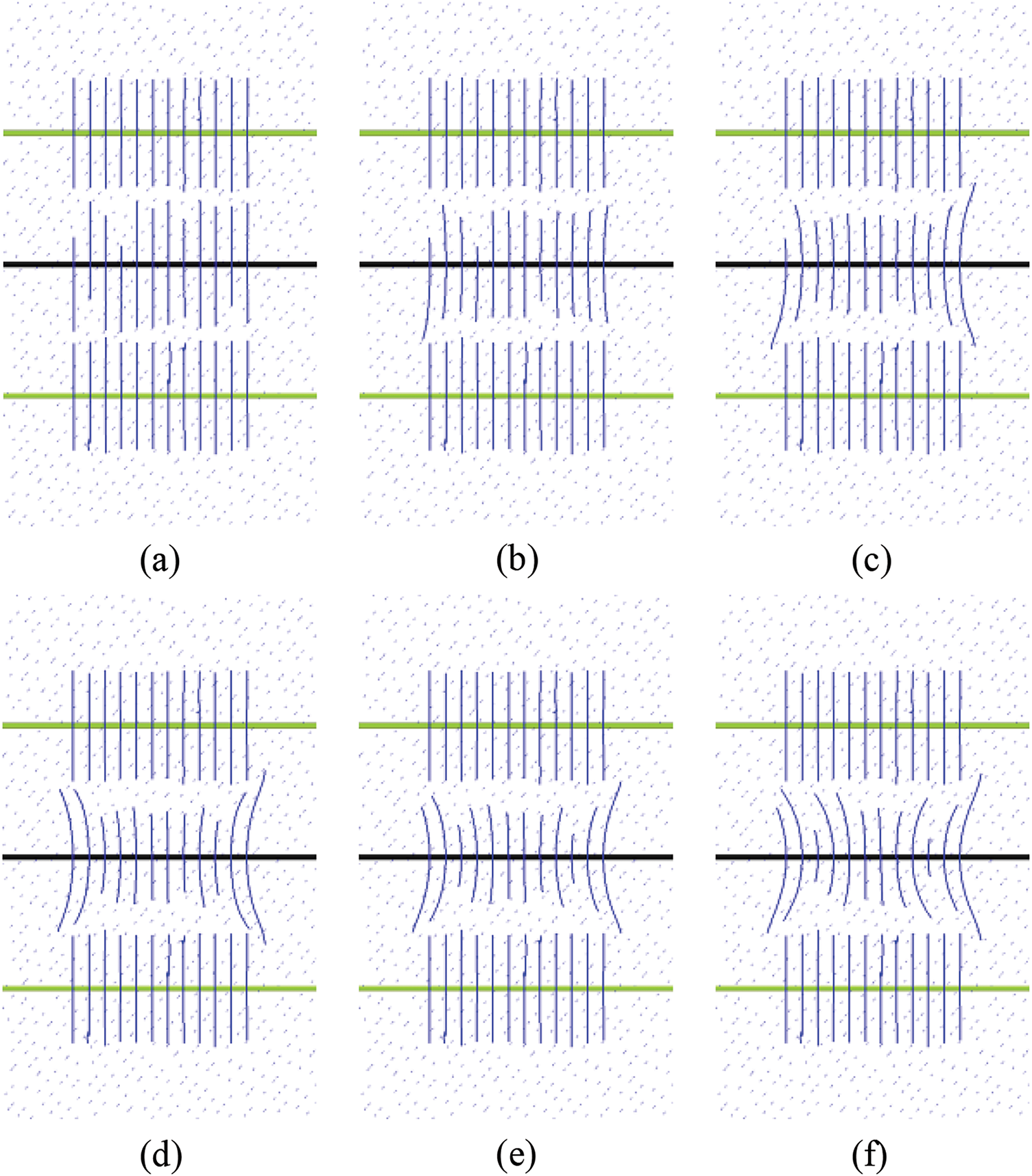
Figure 14: Distribution of fracture propagation patterns for infill wells at different infill timings: (a–f) represent the parent well production at 0, 1, 3, 5, 7, and 10 years, respectively
Table 2 shows the simulated statistical results of hydraulic fractures in infill wells at different fracturing times. By analyzing the data in the table, the following conclusions can be drawn:
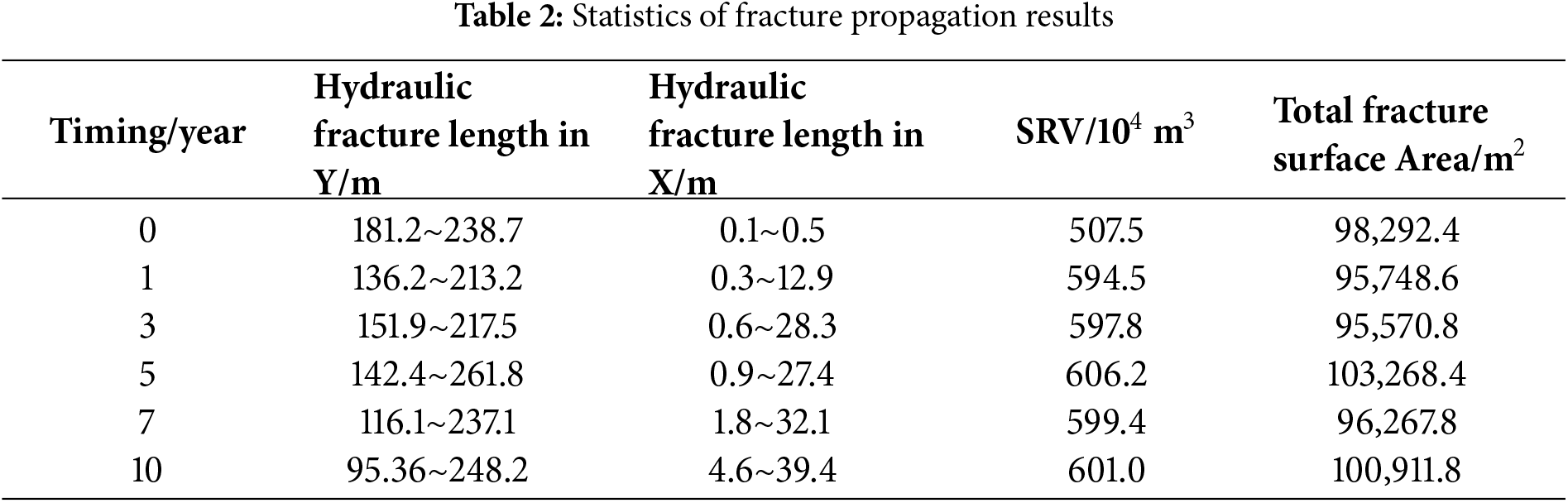
As the fracturing time is delayed, the increased diversion of fractures enhances their complexity. This increase in complexity helps to form a more intricate fracture network to some extent. However, it also limits the extension of some fractures in the length direction, resulting in a reduced overall stimulated volume.
This indicates that while increased fracture complexity may improve oil and gas recovery, excessively delaying the fracturing time is not always beneficial. Therefore, there is an optimal timing for fracturing infill wells. At this optimal time, fracturing not only creates a complex fracture network but also maximizes the stimulated area, thereby enhancing overall production efficiency.
In practical operations, identifying this optimal timing requires a comprehensive consideration of various factors, including formation conditions, production history, and economic benefits. Therefore, reasonably selecting and optimizing the fracturing time is of significant importance for maximizing the productivity and benefits of the well group.
In order to compare the fracture stimulation of infill wells at different fracturing timings, we conducted a simulation analysis of the production changes in well groups after 20 years of production for each well. To minimize the impact of changes in the production regime of old wells on the overall production of the well group, all three wells in the gas reservoir simulation were initially operated at a constant production rate, followed by constant bottom hole pressure production with a bottom hole pressure of 10 MPa. Fig. 15a,b shows the steady production time and cumulative gas production of the well group after infill well fracturing at different times, respectively. As shown in Fig. 15, the earlier the fracturing time of the infill wells, the longer the steady production period, but the cumulative production is smaller in the later stage. From the change in cumulative production of the well group Fig. 15b, it can be seen that with a well spacing of 500 m, if the infill timing is later than the fifth year, both the parent and infill wells show a decrease in cumulative gas production. Deploying infill wells for fracturing in the fifth year of production results in the highest cumulative production for the well group in the later stage.
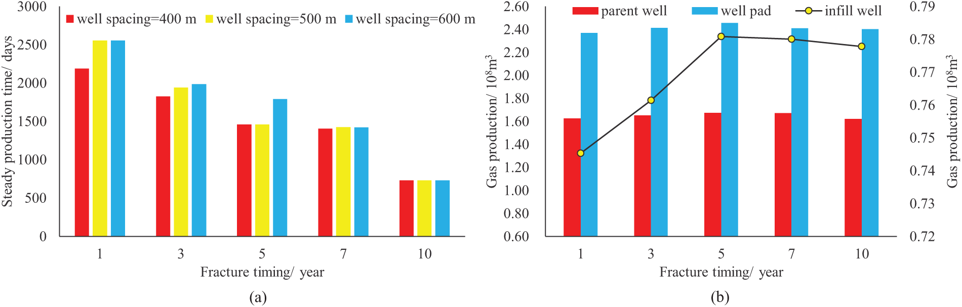
Figure 15: The hydraulic fracturing stimulation for different infill well fracturing timings: (a) steady production time of the well group; (b) cumulative gas production of the parent well, infill well, and the entire well group
Based on the analysis of key factors such as shale reservoir pressure, hydraulic fracturing transformation extent, and fracture density, conducting infill well fracturing in a target area with a parent well spacing of 500 m after 5 years of well group production can achieve optimal production results. At this time, the reservoir pressure has not yet fully depleted, and the fracture distribution and control range are relatively reasonable, which can optimize production.
1. In the study of horizontal well group development in shale gas reservoirs, it is important to consider the direction of the maximum horizontal principal stress between wells and its variation characteristics. During the development period, the change in pore pressure between wells is relatively small, with a reduction of no more than 0.1 MPa. However, the maximum horizontal principal stress among the three principal stresses decreases significantly, while the changes in the minimum horizontal principal stress and vertical stress are not substantial. This may lead to a change in the stress state (during parent well production, the inter-well stress state may shift from a strike-slip to a normal stress state).
2. The reversal time of the horizontal principal stress direction exhibits spatiotemporal dynamic characteristics, especially at the midpoint between wells and in the fractured zone. As production time increases, the horizontal principal stress direction is more likely to reverse. By carefully selecting the timing of infill well fracturing, this characteristic can be utilized to form a complex fracture network while achieving a larger transformation range, thereby increasing the cumulative gas production.
3. Due to variations in the physical properties of different shale reservoirs, inter-well distances of old wells, scale of transformation, fracture density, and production regimes, it is challenging to uniformly determine the timing for infill drilling. It is recommended to consider formation parameters, changes in formation pressure, and other factors specific to each well area, and to use the optimization methods discussed in this paper as a reference to select the optimal timing for infill well fracturing.
However, it should be noted that our current study has certain limitations. We have considered natural fractures in the fracturing model, but the shapes of these fractures are relatively simple, so the simulated hydraulic fractures resemble simple fractures. This differs from the complex fracture networks that may form in actual shale hydraulic fracturing. Additionally, in the mechanical model, we have assumed linear elastic behavior, whereas real shale may exhibit some plasticity. This opens an interesting direction for future research.
Lastly, we emphasize that our work primarily focuses on theoretical modeling, but the model parameters are based on real-world scenarios. As discussed in Section 4, we optimized the infill well fracturing timing based on the evolution of the in-situ stress and developed a timing optimization template for a given shale reservoir, which has practical significance. Regarding the application of these findings in real-world scenarios, we believe more detailed analysis and optimization work are required. From this perspective, future research can place greater emphasis on the potential impacts of different shale reservoirs and their inherent variability (such as fracture density and pore pressure), which would broaden the applicability of this study.
Acknowledgement: The authors would like to thank the reviewers and editors for their useful suggestions for improving the quality of our manuscript.
Funding Statement: This work was supported by the National Natural Science Foundation of China (Grant No. 52374043) and the Southwest Oil & Gas Field Branch in PetroChina (Grant No. JS2023-115).
Author Contributions: The authors confirm contribution to the paper as follows: study conception and design: Huiying Tang, Qi Deng and Qi Ruan; data collection: Qiang Liu and Qi Deng; analysis and interpretation of results: Qi Deng, Bo Zeng and Qi Ruan; draft manuscript preparation: Qi Ruan, Qi Deng, Yi Song and Shen Cheng. All authors reviewed the results and approved the final version of the manuscript.
Availability of Data and Materials: The datasets generated and/or analyzed during the current study are available from the corresponding author on reasonable request.
Ethics Approval: Not applicable.
Conflicts of Interest: The authors declare no conflicts of interest to report regarding the present study.
References
1. Zou CN, Dong DZ, Wang YM, Li JL, Huang JL, Wang SF, et al. Shale gas in China: characteristics, challenges and prospects (I). Pet Explor Dev. 2015;42(6):689–701. doi:10.1016/S1876-3804(15)30072-0. [Google Scholar] [CrossRef]
2. He ZL, Nie HK, Hu DF, Jiang TX, Wang RY, Zhang YY, et al. Geological problems in the effective development of deep shale gas: a case study of upper Ordovician Wufeng-lower Silurian Longmaxi formations in Sichuan Basin and its periphery. Acta Pet Sin. 2020;41(4):379–91. [Google Scholar]
3. Zhang T, Luo SG, Zhou HJ, Hu HR, Zhang LH, Zhao YL, et al. Pore-scale modelling of water sorption in nanopore systems of shale. Int J Coal Geol. 2023;273(4):104266. doi:10.1016/j.coal.2023.104266. [Google Scholar] [CrossRef]
4. Wang HY, Liu YZ, Dong DZ, Zhao Q, Du D. Scientific issues on effective development of marine shale gas in southern China. Pet Explor Dev. 2013;40(5):574–8. doi:10.1016/S1876-3804(13)60080-4. [Google Scholar] [CrossRef]
5. Lei Q, Xu Y, Cai B, Guan BS, Wang X, Li H, et al. Progress and prospects of horizontal well fracturing technology for shale oil and gas reservoirs. Pet Explor Dev. 2022;49(1):166–172, 182. doi:10.1016/S1876-3804(22)60015-6. [Google Scholar] [CrossRef]
6. Miller G, Lindsay G, Baihly J, Xu T. Parent well refracturing: economic safety nets in an uneconomic market. In: Proceedings of the SPE Low Perm Symposium; 2016 May 5–6; Denver, CO, USA. SPE-180200-MS. [Google Scholar]
7. Akash D, Kousic K, Raj M. Sequencing hydraulic fractures to optimize production for stacked well development in the delaware basin. In: Proceedings of the SPE/AAPG/SEG Unconventional Resources Technology Conference; 2020 Jul 20–22; Austin, TX, USA. [Google Scholar]
8. Kumar A, Shrivastava K, Elliott B, Sharma M. Effect of parent well production on child well stimulation and productivity. In: Proceedings of the SPE Hydraulic Fracturing Technology Conference and Exhibition; 2020 Feb 4–6. Woodlands, TX, USA. SPE-199700-MS. [Google Scholar]
9. Pei Y, Sepehrnoori K. Investigation of parent-well production induced stress interference in multilayer unconventional reservoirs. Rock Mech Rock Eng. 2022;55(5):2965–86. doi:10.1007/s00603-021-02719-1. [Google Scholar] [CrossRef]
10. Evans AB, Kondo SKO, Borsah AA, Brantson ET. Critical evaluation of infill well placement and optimization of well spacing using the particle swarm algorithm. J Pet Explor Prod Technol. 2019;9(4):3113–33. doi:10.1007/s13202-019-0710-1. [Google Scholar] [CrossRef]
11. Maity D, Ciezobka J. Novel proppant logging technique for infill drilling of unconventional shale wells. SPE Reserv Eval Eng. 2022;25(3):641–54. doi:10.2118/209790-PA. [Google Scholar] [CrossRef]
12. Malhotra S, Lerza A, Cuervo S. Well spacing and stimulation design optimization in the vaca muerta shale: hydraulic fracture simulations on the cloud. In: Proceedings of the SPE Hydraulic Fracturing Technology Conference and Exhibition; 2021 May 4–6. SPE-204142-MS. [Google Scholar]
13. Dong ZZ, Holditch SA, Mcvay DA, Ayers WB, Lee WJ, Morales E. Probabilistic assessment of world recoverable shale-gas resources. SPE Econ Manag. 2015;7(2):72–82. doi:10.2118/167768-PA. [Google Scholar] [CrossRef]
14. Pankaj P, Shuklap P, Kavousi P, Carr T. Determining optimal well spacing in the Marcellus shale: a case study using an integrated workflow. In: Proceedings of the SPE Argentina Exploration and Production of Unconventional Resources Symposium; 2018 Aug 14–16; Neuquen, Argentina. SPE-191862-MS. [Google Scholar]
15. Sun HQ, Cai XY, Hu DG, Li ZY, Zhao PR, Zheng AX, et al. Theory, technology and practice of shale gas three-dimensional development: a case study of Fuling shale gas field in Sichuan Basin, SW China. Pet Explor Dev. 2023;50(3):573–84. doi:10.1016/S1876-3804(23)60417-3. [Google Scholar] [CrossRef]
16. Lei Q, Yang LF, Duan YY, Weng DW, Wang X, Guan BS, et al. The fracture-controlled reserves based stimulation technologyfor unconventional oil and gas reservoirs. Pet Explor Dev. 2018;45(4):719–26. doi:10.1016/S1876-3804(18)30080-6. [Google Scholar] [CrossRef]
17. Asadi R, Ataie-Ashtiani B. Hybrid finite volume-finite element methods for hydro-mechanical analysis in highly heterogeneous porous media. Comput Geotech. 2021;132(3–4):103996. doi:10.1016/j.compgeo.2020.103996. [Google Scholar] [CrossRef]
18. Cipollac L, Motiee M, Kechemir A. Integrating microseismic, geomechanics hydraulic fracture modeling, and reservoir simulation to characterize parent well depletion and infill well performance in the Bakken. In: Proceedings of the SPE/AAPG/SEG Unconventional Resources Technology Conference; 2018 Jul 23–25; Houston, TX, USA. URTEC-2899721-MS. [Google Scholar]
19. Mcintyre R, Gaines J, Gardner S, Mediani M, Hammerquist C, Li X, et al. Predictive geologic and geomechanical models for pad development in the delaware basin. In: Proceedings of the SPE/AAPG/SEG Unconventional Resources Technology Conference; 2020 Jul 20–22; Austin, TX, USA. URTEC-2020-3309-MS. [Google Scholar]
20. Jacobs T. Oil and gas producers find Frac Hits in shale wells a major challenge. J Pet Technol. 2017;69(4):29–34. doi:10.2118/0417-0029-JPT. [Google Scholar] [CrossRef]
21. Wood T. Leonard R, Senters C, Squires C, Perry M. Interwell communication study of UWC and MWC wells in the HFTS. In: Proceedings of the SPE/AAPG/SEG Unconventional Resources Technology Conference; 2018 Jul 23–25; Houston, TX, USA. URTEC-2902960-MS. [Google Scholar]
22. Zhu HY, Tang XH, Song YJ, Li KD, Xiao JL, Dusseault MB, et al. An infill well fracturing model and its microseismic events barrier effect: aa case in fuling shale gas reservoir. SPE J. 2021;26(1):113–34. doi:10.2118/202485-PA. [Google Scholar] [CrossRef]
23. Dohmen T, Zhang J, Barker L, Blangy JP. Microseismic magnitudes and b-values for delineating hydraulic fracturing and depletion. SPE J. 2017;22(5):1624–34. doi:10.2118/186096-PA. [Google Scholar] [CrossRef]
24. Rezaei A, Rafiee M, Bornia G, Soliman M, Morse S. Protection refrac: analysis of pore pressure and stress change due to refracturing of legacy wells. In: Proceedings of the SPE/AAPG/SEG Unconventional Resources Technology Conference; 2017 Jul 24–26; Austin, TX, USA. RTEC-2667433-MS. [Google Scholar]
25. Gupta J, Zielonka MG, Albert RA, EI-Rabaa W, Burnham HA, Choi NH. Integrated methodology for optimizing development of unconventional gas resources. In: Proceedings of the SPE Hydraulic Fracturing Technology Conference; 2012 Feb 6–8; Woodlands, TX, USA. SPE-152224-MS. [Google Scholar]
26. King GE, Rainbolt MF, Swanson C. Frac Hit induced production; losses evaluating root causes, damage location, possible prevention methods and success of remedial treatments. In: Proceedings of the SPE Annual Technical Conference and Exhibition; 2017 Oct 9–11; San Antonio, TX, USA. SPE-187192-MS. [Google Scholar]
27. Nasrollahzadeh B, Akhlaghi AH, Ghabezloo S. Field-scale fully coupled simulation of fluid flow and geomechanics: gas storage/recovery process in a depleted sandstone reservoir. J Pet Sci Eng. 2021;200(2):108423. doi:10.1016/j.petrol.2021.108423. [Google Scholar] [CrossRef]
28. Tang XH, Rutqvist J, Hu MS, Rayudu NM. Modeling three-dimensional fluid-driven propagation of multiple fractures using TOUCH-FEMM. Rock Mech Rock Eng. 2019;52(2):611–27. doi:10.1007/s00603-018-1715-7. [Google Scholar] [CrossRef]
29. Rezaei A, Dindoruk B, Mohamed YS. On parameters affecting the propagation of hydraulic fractures from infill wells. J Pet Sci Eng. 2019;182(3):106255. doi:10.1016/j.petrol.2019.106255. [Google Scholar] [CrossRef]
30. Rezaei A, Nakshatrala KB, Siddiqui F, Dindoruk B, Soliman M. A global sensitivity analysis and reduced order models for hydraulically-fractured horizontal wells. Comput Geosci. 2020;24(3):995–1029. doi:10.1007/s10596-019-09896-7. [Google Scholar] [CrossRef]
31. Verde A. Global sensitivity analysis of geomechanical fractured reservoir parameters. In: Proceedings of the 49th U.S. Rock Mechanics/Geomechanics Symposium; 2015 Jun 28–Jul 1; San Francisco, CA, USA. ARMA-2015-748. [Google Scholar]
32. Guo X, Wu K, Killough J. Investigation of production-induced stress changes for infill-well stimulation in Eagle Ford shale. SPE J. 2018;23(4):1372–88. doi:10.2118/189974-PA. [Google Scholar] [CrossRef]
33. Weng X, Kresse O, Cohen C, Wu R, Gu H. Modeling of hydraulic-fracture network propagation in a naturally fractured formation. SPE Prod Oper. 2011;26(4):368–80. doi:10.2118/140253-MS. [Google Scholar] [CrossRef]
34. Weng X. Modeling of complex hydraulic fractures in naturally fractured formation. J Unconv OilGas Resour. 2015;9(1):114–35. doi:10.1016/j.juogr.2014.07.001. [Google Scholar] [CrossRef]
35. Wu K, Olson JE. Simultaneous multifracture treatments: ffully coupled fluid flow and fracture mechanics for horizontal wells. SPE J. 2015;20(2):337–46. doi:10.2118/167626-PA. [Google Scholar] [CrossRef]
Cite This Article
 Copyright © 2025 The Author(s). Published by Tech Science Press.
This work is licensed under a Creative Commons Attribution 4.0 International License , which permits unrestricted use, distribution, and reproduction in any medium, provided the original work is properly cited.
 Downloads
 Citation Tools