
 Submit a Paper
 Propose a Special lssue
 Open Access
ARTICLE

Numerical Analysis of Dual Atomizing Nozzle Jets in a Waste Warehouse
1 Waste Incineration Division, CUCDE Environmental Technology Co., Ltd., Beijing, 100120, China
2 Renqiu Shenneng Environment Co., Ltd., Renqiu, 061000, China
3 Department of Power Engineering, North China Electric Power University, Baoding, 071003, China
* Corresponding Author: Xuemin Ye. Email:
Fluid Dynamics & Materials Processing 2025, 21(5), 1063-1077. https://doi.org/10.32604/fdmp.2025.063769
Received 23 January 2025; Accepted 24 March 2025; Issue published 30 May 2025
 View Full Text
 Download PDF
Abstract
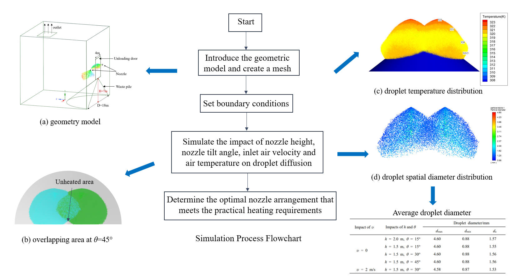
Enhancing the fermentation efficiency of waste in waste warehouses is pivotal for accelerating the pyrolysis process and minimizing harmful gas emissions. This study proposes an integrated approach, combining hot air injection with dual atomizing nozzles, for the thermal treatment of waste piles. Numerical simulations are employed to investigate the influence of various parameters, namely, nozzle height, nozzle tilt angle, inlet air velocity and air temperature, on the droplet diffusion process, spread area, droplet temperature, and droplet size distribution. The results show that reducing the nozzle height increases the temperature of droplets upon their deposition on the waste pile. Specifically, when the nozzle height is lowered to 1.5 m, the temperature of the droplets reaching the waste pile is 1°C higher than when the nozzle height is set at 2 m. Furthermore, an increase in the nozzle tilt angle expands the overlapping heating area. For instance, when the nozzle angle is increased from 15° to 30°, the overlapping spread area expands by 3.21 m2. Additionally, increasing the inlet air velocity enhances the droplet diffusion range. At an air velocity of 2 m/s, the droplet diffusion range grows to 14.4 m, representing a 6.7% increase compared to the no-wind condition. While the average droplet diameter decreases to 1.53 mm, the droplet temperature decreases by 1°C. Moreover, the droplet temperature is found to become smaller as the ambient temperature inside the waste warehouse declines. Specifically, a 5°C reduction in the ambient temperature results in a 1°C decrease in the average temperature of the atomized droplets. The study concludes that a nozzle height of 1.5 m and a nozzle tilt angle of 30° effectively meet practical heating requirements.Graphic Abstract
Keywords
Waste-to-energy incineration technology represents a critical method for the harmless treatment of waste and the sustainable utilization of energy [1,2]. In the waste incineration process, the pretreatment of waste and the regulation of pile temperature are pivotal for optimizing waste fermentation efficiency, accelerating pyrolysis, and mitigating harmful gas emissions [3–5]. Chen et al. [6] identified that 15°C is the minimum temperature required to initiate the biological degradation of municipal solid waste, and effective fermentation only occurs once the temperature exceeds this threshold. In cold regions [7], waste piles often experience low temperatures or even freezing. To mitigate this, certain waste-to-energy incineration plants co-incinerate straw fuel or high-calorific-value fossil fuels in specified proportions [8]. However, this approach not only escalates operational costs but also hampers the growth of the waste-to-energy sector [9]. Therefore, the development of technological solutions that maintain the waste pile temperature while minimizing operational expenses has become a pressing concern in the industry.
Current literature and operational practices indicate that heating the waste pile and maintaining its temperature can significantly enhance the fermentation environment and address this issue effectively [10–13]. Adetunji et al. [11] investigated the biorefining technology of organic solid waste, which facilitates the conversion of organic waste into biofuels or other high-value products within the waste warehouse, all while maintaining the optimal temperature. This strategy not only reduces operational costs for incineration plants but also enhances resource utilization efficiency. In municipal solid waste landfill systems, Yaashikaa et al. [12] examined the environmental and economic impacts of leachate and gas emissions and proposed strategies for maintaining pile temperature through optimized landfill design and targeted heating methods. Several heating strategies for waste piles have been explored in existing research. Luo et al. [14] utilized primary air and furnace wall cooling air as heat sources, which were directed into the waste pile via an induced draft fan to elevate its temperature. Khan et al. [15] employed leachate heating and recirculation, though these methods were not effective in practical operations. Zhang et al. [16] used turbine extraction to directly heat the waste pile, but these methods suffer from issues related to system complexity, cost-efficiency, and suboptimal resource utilization, rendering them impractical for widespread implementation. Therefore, further refinement of waste pile heating technologies is essential.
In response to these limitations, several waste-to-energy incineration companies [17] have experimented with various combined heating approaches, which includes injecting hot air above the waste pile and simultaneously introducing heated liquid from both sides. However, challenges such as the considerable distance between the hot air inlet and the waste pile, coupled with the large volume of the waste warehouse, mean that the hot air is insufficient to significantly increase the temperature of the waste pile. Furthermore, the leachate outlets typically consist of pipe nozzles, discharging the liquid in a columnar form that only covers a limited area of the pile. Current operational observations [18] indicate that even with these combined methods, the temperature of the waste pile often fails to meet the necessary requirements for effective waste fermentation.
Recent studies suggest that atomizing nozzles offer significant advantages in terms of liquid atomization and heat transfer efficiency. Proper atomization results in a reduced Sauter Mean Diameter (SMD), which significantly enhances burner stability and extends the operational life of heat-exposed components [19,20]. Shams Ghahfarokhi et al. [21] analyzed spray cooling technology, highlighting its high heat transfer coefficient, uniform temperature distribution, low superheating, and high critical heat flux density. Wu et al. [22,23] utilized a discrete phase model (DPM) to analyze multi-nozzle atomization and dual-medium nozzle atomization, investigating the effects of nozzle angle, spacing, and other parameters on atomization flow fields. Their findings indicated that increasing the nozzle angle enhances the droplet overlapping area and extends droplet residence time. Liu et al. [24] employed a DPM model to study the effects of double/triple nozzles and nozzle spacing on primary jet break-up and droplet size distribution, finding that increasing the number of nozzles reduced the average droplet diameter and promoted early jet polymerization. Although existing research on droplet atomization primarily focuses on single-nozzle models and the impact of multi-nozzle configurations on droplet size variation, there is a notable gap in studies investigating the use of dual nozzles aimed at heating waste piles. As waste piles naturally form in a conical shape, two vertically downward jets are inadequate for uniformly covering most of the pile with atomized droplets. In contrast, jets directed at an angle to the wall can significantly improve coverage in a shorter time. However, studies addressing the use of angled dual jets for heating waste piles remain scarce.
To address this gap, the present study proposes an integrated heating method involving “hot air injection + dual atomizing nozzles” for waste pile heating in a waste warehouse. Specifically, while maintaining the hot air injection system unchanged, the leachate pipe nozzles are replaced with atomizing nozzles angled towards the walls. A dual solid-cone nozzle [25] is employed to atomize the liquid column from the nozzles into numerous small droplets. Numerical simulations are conducted to evaluate the performance of dual atomizing nozzles, investigating the effects of nozzle height, tilt angle, and inlet wind speed and temperature on the diffusion process, droplet temperature, and droplet size distribution. The optimal configuration that meets the heating requirements of the waste pile is identified, providing a theoretical basis for the design and retrofitting of waste warehouses.
Fig. 1a shows a schematic of the waste warehouse, with an unloading door that is 4 m wide and 6 m high. The waste is dumped through the unloading door into the waste warehouse, where it naturally piles up to form a conical structure. The height of the waste pile is 7 m, and the radius of the base is 9 m. Atomizing nozzles with a diameter of 50 mm are installed on both sides of the unloading door, positioned 0.2 m from the door and extending 0.1 m into the waste warehouse. The leachate mass flow rate through the atomizing nozzles is 3.52 kg/s, meaning the nozzles spray the leachate into the waste warehouse at an initial velocity of 25 m/s, with an initial temperature of 50°C.
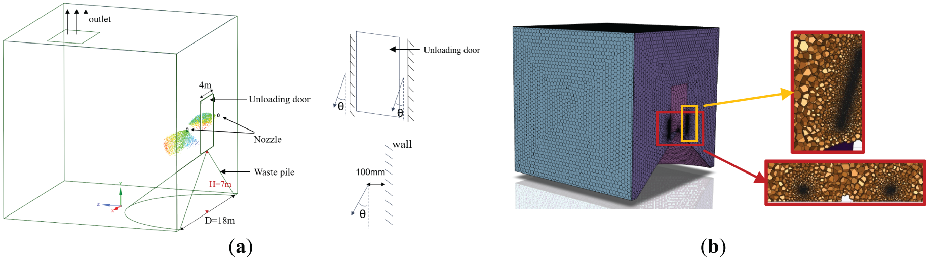
Figure 1: Computational domain and grid meshing. (a) Geometry model and nozzle position diagram; (b) global grid and loacal grid refinement
In the simulation, the fluid computational domain corresponds to the internal space of the waste warehouse, specifically the region outside the waste pile. The unloading door serves as the air inlet, with dimensions of 4 m × 6 m. On both sides of the unloading door, atomizing nozzle inlets with a diameter of 50 mm are arranged for leachate injection. A rectangular region of 4 m × 6 m at the top of the waste warehouse acts as the outlet. Two jets are directed at an angle to the wall, and the nozzle is positioned 100 mm away from the wall. As this study focuses on the diffusion of droplets exclusive of the jet break-up, the influence of the wall is not considered. Fluent meshing was used to divide the 3D grid, with local refinement applied to the spraying area due to the presence of spray holes on both sides of the unloading door. Since simulation primarily focuses on the spray range of droplets and their heat dissipation in the air, the boundary layer was not taken into account. The global minimum mesh size was set to 0.26 mm, while the maximum mesh size was 50 mm, with a mesh growth rate of 1.2. The total number of mesh elements was 2.4 million, with 0.8 million elements in the locally refined region, as illustrated in Fig. 1b.
The governing equations include the continuity equation, Reynolds-averaged Navier-Stokes equations, the Standard k-ε turbulence model, and the energy equation [26], as follows:
where
The Discrete Phase Model (DPM) is used to simulate the evolution of atomized droplets in space. This method follows the Euler-Lagrange approach, where air is treated as the continuous phase and liquid particles as the discrete phase. These two phases can exchange momentum, mass, and energy. The DPM model assumes that the particles are spherical and uniformly distributed within the continuous phase, with the volume fraction of the discrete phase being very small, typically not exceeding 10%. Therefore, the influence of particles on the continuous phase and the interaction between particles can be neglected. In the simulation, each particle is treated as an individual entity. The flow field of the continuous phase is first calculated, and then the forces and velocities acting on the particles are determined based on the flow field variables, which allows for the calculation of the particle trajectories. This study focuses on the atomization process and spatial distribution of the droplets, so radial velocity along the centerline of the spray nozzle is set at the nozzle outlet. Additionally, the KH-RT (Kelvin-Helmholtz-Rayleigh-Taylor) breakup model and the random walk model are used to track the particle trajectories. This model inherently accounts for droplet breakup and potential coalescence during the initial spray formation process [22–24]. The DPM characterizes the droplet breakup process at the nozzle outlet using the KH-RT breakup model. This model predicts droplet fragmentation and size distribution based on turbulence characteristics. The maximum and minimum droplet diameters are defined within the range of the Rosin-Rammler distribution function, while the mean droplet diameter is determined using the SMD, which represents the ratio of droplet volume to surface area. The boundary condition for the particles at the inlet and outlet is set to escape, while the remaining wall boundaries are set to reflect. In the simulation, the droplet distribution follows the Rosin-Rammler model, with the initial minimum droplet diameter dmin, maximum droplet diameter dmax, and average droplet diameter da set to 3, 5, and 4 mm, respectively. The diffusion parameter is 3.9, and 30 streams of droplets are initially injected [27,28]. Due to the wide range of droplet sizes resulting from atomization fragmentation, the Sauter Mean Diameter (SMD) is used to assess the atomization quality [24]. The simulation employs a pressure-based solver for transient solutions, with the SIMPLE algorithm used to couple pressure and velocity. The momentum and energy equations are discretized using a second-order upwind scheme, while the turbulent kinetic energy and turbulence dissipation rate equations use a first-order upwind scheme. The relaxation factors are adjusted according to the actual conditions to ensure convergence, with normalized residuals less than 10−5. Given the constraints of computational resources and the specific objectives of the study, the simulation duration is set to 1 s to ensure efficiency and accuracy.
2.3 Grid Independence Verification and Model Validation
Taking an example with a nozzle exit velocity of 25 m/s, air inlet temperature tf of 303 K at the unloading door, and inlet flow velocity υ of 2 m/s, the average velocity at the waste warehouse outlet and the average droplet diameter are selected as characteristic parameters. Mesh independence is verified using mesh numbers of 0.8 million, 1.8 million, 2.4 million, 3.4 million, and 4.2 million. Fig. 2 shows that when the mesh number exceeds 2.4 million, both the outlet average velocity and the average droplet diameter remain unchanged. Considering the balance between computational accuracy and efficiency, a mesh number of 2.4 million is chosen for the numerical simulation in the following analysis.
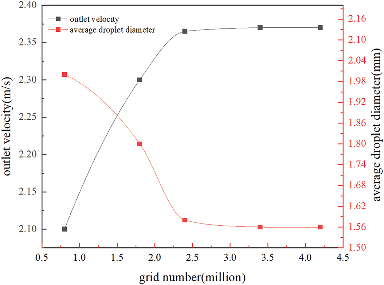
Figure 2: Grid independence verification
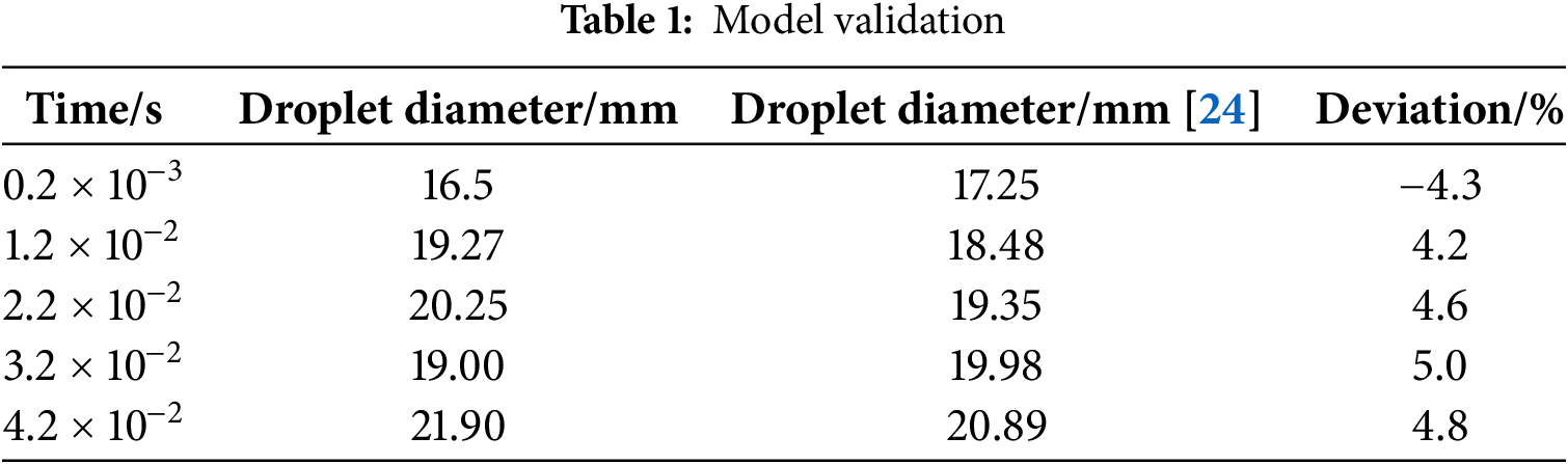
Based on the simulation method proposed in this study, we validate the findings reported in the literature [24] for similar scenarios. By calculating the deviation between the simulation results and the reported data, we assess the accuracy of the present simulations. Table 1 shows that the deviation is less than 5%, which is within an acceptable range. Hence, the simulation method used in this study can effectively predict the diffusion dynamics of the atomizing droplets within the waste warehouse.
To analyze the effects of nozzle installation height, nozzle tilt angle, inlet wind velocity and temperature at the unloading door, as well as the impact of summer and winter temperatures inside the waste warehouse, the conducted simulation cases are listed in Table 2. The specific details are as follows:
(1) In typical heating of the waste pile, the unloading door is closed, or considering that the inlet wind speed υ is usually 0–2 m/s, the impact of inlet wind velocity is initially ignored in the study. Additionally, since the waste pile is conical in shape and the height of the waste is most significant near the apex of the cone, this area requires more atomized droplets for heating compared to other regions. Therefore, two nozzles are arranged at an angle, creating an overlapping spread area near the waste pile top for repeated heating in this region (as opposed to single heating in other areas). The nozzle tilt angle (the angle between the jet centerline and the y-axis) is assumed to be θ = 15°. Furthermore, to facilitate maintenance of the atomizing nozzles, the nozzle installation height h is set to 2.0 and 1.5 m, respectively. Lastly, considering that the temperatures inside the waste warehouse in summer and winter differ, they are set to t∞ = 35°C and t∞ = 30°C, respectively.
(2) Based on the results of case 1 (see the subsequent analysis), the spread range and overlapping heating area with a nozzle height of h = 1.5 m basically meet the requirements. On this basis, the spread range and overlapping heating area are compared for nozzle tilt angles of θ = 15°, 30°, and 45°, with the warehouse temperatures t∞ = 35°C and t∞ = 30°C, in order to determine the optimal nozzle tilt angle of 30°.
(3) Based on the results of case 2, under the conditions of h = 1.5 m and θ = 30°, the effects of an unloading door wind speed of υ = 2 m/s and inlet wind temperatures tf = 30°C in summer and tf = 10°C in winter are analyzed.
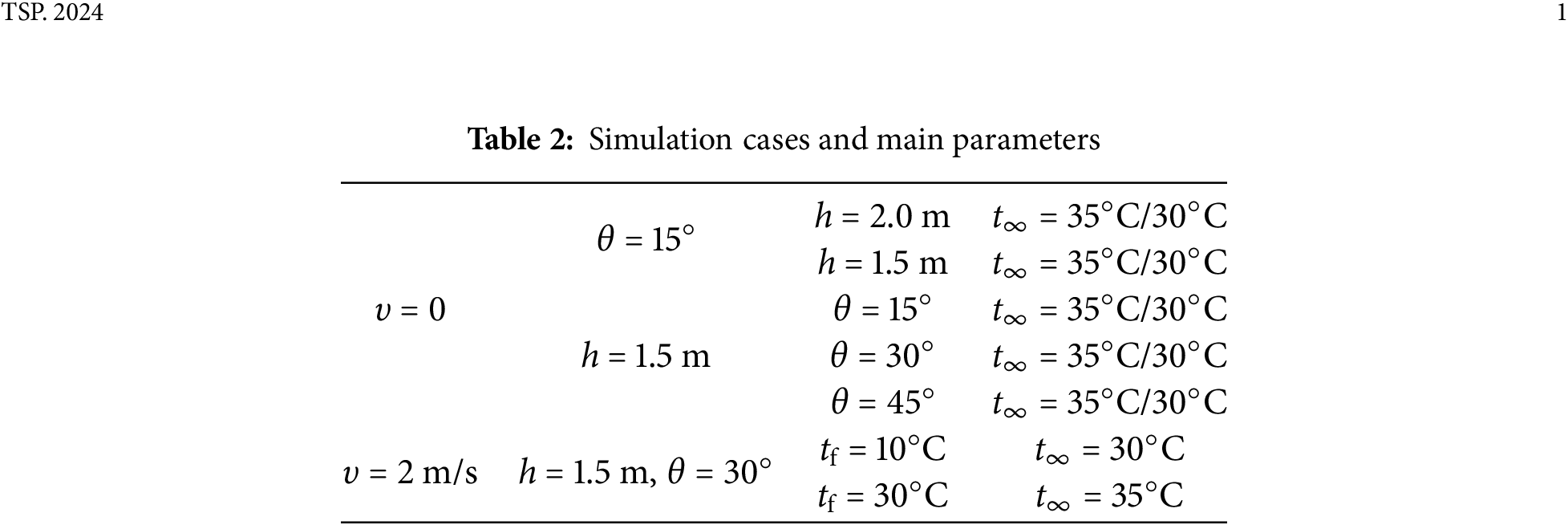
Fig. 3 shows the effect of nozzle installation height (h = 2 m and 1.5 m) on the spread range of atomized droplets and the overlapping heating area under θ = 15° and t∞ = 35°C. It is seen that the droplet diffusion characteristics under both nozzle heights exhibit good stability, with highly similar spatial distributions and spreading profiles. Under no wind condition of υ = 0, the interference from the surrounding air on the droplet breakup process is minimized, and the atomization and diffusion of droplets in space maintain a symmetrical distribution.
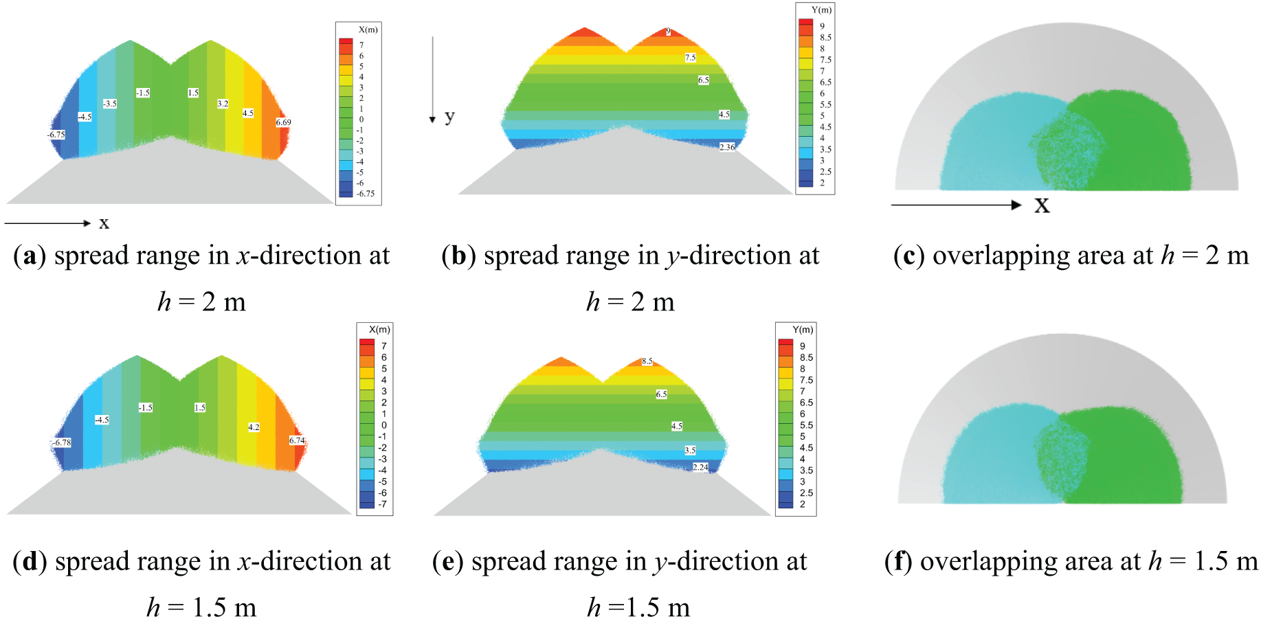
Figure 3: Effect of different nozzle heights on droplet diffusion range and overlapping area
For the case of h = 2 m, in the x-direction, the total spreading width of the droplets 1 s after spraying reaches 13.5 m, covering about two-thirds of the horizontal waste pile. Additionally, in the y-direction, the droplet’s falling height reaches 6.6 m, covering two-thirds of the pile’s height. The atomized droplets effectively cover the majority of the waste pile area, and the corresponding waste pile volume accounts for about 60% of the total volume, thus heating the majority of the waste pile in just 1 s. It is important to note that the waste pile exhibits a near-conical shape, with the highest accumulation of waste located near the apex. Consequently, this region demands the greatest amount of heat from the atomized droplets. Under equivalent conditions, applying repeated heating in this area is advantageous in meeting the thermal requirements for the waste at the base. As time progresses, it can be inferred that the atomized droplets continue to diffuse in both the x and y directions, eventually covering the entire waste pile volume. By comparing the spreading range of droplets in the x and y directions, it is seen that the diffusion capability of atomized droplets is the same in both directions.
For the case of h = 1.5 m, the spread range of atomized droplets 1 s after spraying in both the x and y directions is similar to that of h = 2 m. The only difference is that the spreading height in the y-direction decreases by 0.5 m. This indicates that the nozzle height has a small effect on the overall spreading range. It can be concluded that, compared to the case with h = 2 m, when h = 1.5 m, the reduction in nozzle height decreases the time required for the droplets to diffuse to the waste pile. This, in turn, reduces the heat loss of the droplets during the diffusion process, accelerates the heat exchange between the droplets and the waste pile, and thus improves the heating efficiency of the waste pile.
Comparing Fig. 3c and f, it is found that the overlapping area of the spraying at h = 2 m and 1.5 m are 11.96 and 9.2 m2, respectively, with a difference of 2.76 m2. Although the overlapping area of the former is larger than that of the latter, which facilitates the heating of the waste pile in this region, increasing the height not only raises the temperature drop when the droplets reach the pile, increasing the heat loss during the diffusion process [18], but also amplifies the potential safety risks encountered during maintenance. The reduction in the overlapping area caused by the decreased nozzle height can be addressed by adjusting the nozzle tilt angle, as will be discussed in the following section.
Fig. 4a,c shows the effect of nozzle height on droplet temperature distribution under θ = 15° and t∞ = 35°C. As seen in Fig. 4, the temperature distribution along the droplet’s falling height (i.e., the y-direction) shows a layered structure. The nozzle outlet temperature is the highest at 50°C and gradually decreases as the droplet falls. This is because, during the atomization and diffusion process, the droplets constantly exchange heat with the surrounding environment, resulting in a gradual decrease in temperature along the vertical diffusion direction. Additionally, since the atomized droplets have the same diffusion capability in both the x and y directions, the temperature distribution of the droplets shows a layered characteristic in space.
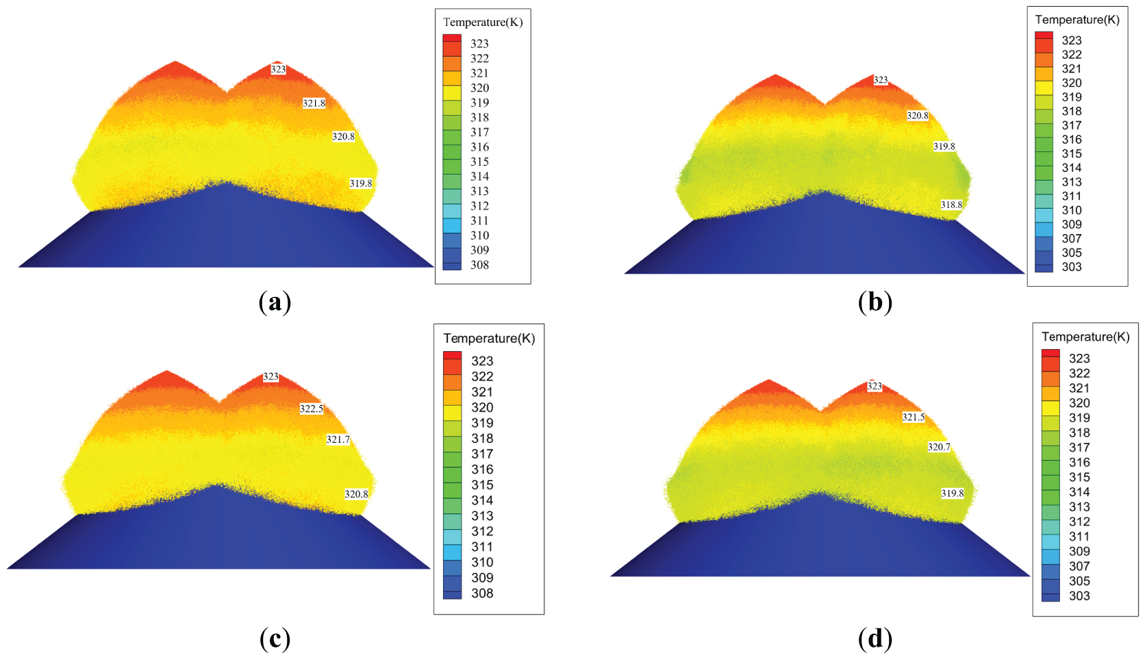
Figure 4: Effect of nozzle height and warehouse temperature on the spatial distribution of droplet temperature. (a) h = 2 m, t∞ = 35°C; (b) h = 2 m, t∞ = 30°C; (c) h = 1.5 m, t∞ = 35°C; (d) h = 1.5 m, t∞ = 30°C
The nozzle height and the warehouse temperature also affect the spatial distribution of droplet temperature. Specifically, for h = 2.0 m and t∞ = 35°C, the average droplet temperatures at y = 9, 7, 5, and 3 m are 50.0°C, 48.8°C, 47.8°C, and 46.8°C, respectively. When the nozzle height is reduced to 1.5 m, the temperatures at y = 8.5, 7, 5, and 3 m are 50.0°C, 49.5°C, 48.7°C, and 47.8°C, respectively. This shows that when the nozzle height is reduced, the temperature drop of the droplets is smaller. When the droplets reach the waste pile, their temperature is 1°C higher than when the height is 2 m, indicating that reducing the nozzle height to 1.5 m can reduce the heat loss of the droplets in space. If h is further reduced to 1.0 m, although the heat loss from the droplets can be further minimized, the overlapping area is significantly reduced, which is detrimental to the heating of the primary region at the top of the waste pile.
Fig. 4a,b shows the change in droplet temperature when t∞ decreases from 35°C to 30°C under the same nozzle height. When t∞ drops by 5°C, the temperature of the droplets at two-thirds of the waste pile decreases from 46.8°C to 45.8°C. This is because lowering the environmental temperature increases the temperature difference between the droplets and the environment, which accelerates the heat transfer from the droplets to the environment, causing the temperature to decrease more significantly.
Comparing the above results, it can be observed that the effects of nozzle height and temperature variation within the warehouse are generally similar. However, the warehouse temperature is more difficult to control due to its larger volume and significant seasonal variations. In contrast, adjusting the nozzle height is easier to implement. As previously analyzed, reducing the nozzle installation height can increase the temperature of droplets upon reaching the surface of the waste pile, which is beneficial for enhancing the heat exchange between the droplets and the waste pile. The reduction in the overlapping area caused by the lower height can be addressed by adjusting the nozzle tilt angle, which is easy to implement [22,23].
Fig. 5 shows the impact of different nozzle angles θ on the spread range and overlapping heating area under h = 1.5 m and t∞ = 35°C. Comparing Fig. 5 with Fig. 3a, it is found that, for all three nozzle angles, approximately 1 s after leaving the nozzle, the spread range of the droplets reaches two-thirds of the waste pile volume. This means that the atomized droplets can achieve heating for the majority of the pile.
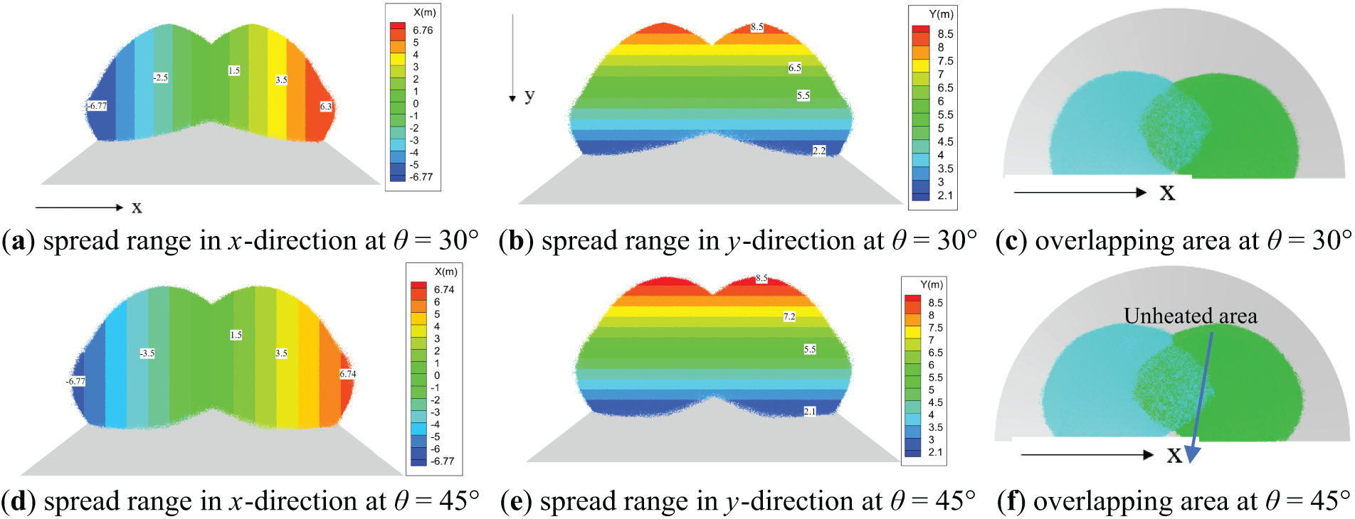
Figure 5: Impact of different nozzle angles on spread range and overlapping area
From Figs. 3c and 5c,f, it can be observed that the overlapping area of the spread range is 9.2 , 12.41, and 13.85 m2 for θ = 15°, 30°, and 45°, respectively. This indicates that nozzle angles of 30° or 45° provide a more extensive coverage of the waste pile, it is more conducive to enhancing the heating efficiency of the upper region of the waste pile. Additionally, considering that the difference in spread range and overlapping area between θ = 30° and θ = 45° is slight, and that at θ = 45°, some areas at the pile top are not heated, it is recommended to use a nozzle angle of θ = 30°.
This configuration not only increases the contact area between the droplets and the waste pile, enhancing heat transfer efficiency, but it also compensates for the reduced overlapping heating area caused by lowering the nozzle height. Specifically, the overlapping area increases from 11.96 m2 at h = 2 m and θ = 15° to 12.41 m2 at h = 1.5 m and θ = 30°.
Fig. 6 shows the effect of different nozzle angles on the droplet temperature distribution at t∞ = 35°C and 30°C. It is shown that when t∞ = 35°C, the average temperature of the atomized droplets when they reach two-thirds of the waste pile is 47.8°C, while when t∞ is reduced to 30°C, the droplet temperature at the same point drops to 46.8°C due to the lower ambient temperature.
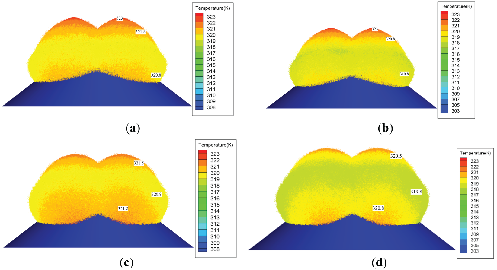
Figure 6: Effect of different nozzle angles on the spatial distribution of droplet temperature. (a) θ = 30°, t∞ = 35°C; (b) θ = 30°, t∞ = 30°C; (c) θ = 45°, t∞ = 35°C; (d) θ = 45°, t∞ = 30°C
Furthermore, Fig. 6 indicates that the nozzle angle affects the temperature distribution of the droplets, resulting in thermal stratification and thereby altering the temperature at different layers. Specifically, for the case with t∞ = 35°C, when the angle θ increases from 30° to 45°, a layer of higher droplet temperature appears near the waste pile. This is because, at a 45° angle, the direction of droplet ejection is more skewed toward the center, causing the droplets at the outer boundary of the jet to remain suspended 1 s after ejection (with the droplet temperature similarly reduced to 47.8°C) and not settle on the surface of the waste pile. Moreover, the central region of the droplet has a smaller heat exchange area with the environment compared to the outer boundary, resulting in a relatively higher temperature. It can also be inferred that when the outermost droplets settle onto the waste pile, they will induce a greater temperature drop than when ejected at a 30° angle.
The inlet wind velocity at the unloading door directly affects the diffusion behaviors of the atomized droplets. It not only alters the droplet fragmentation process and spatial trajectory but also affects the convective heat transfer between the droplets and the environment. In this section, it is assumed that when the unloading door is open, the inlet wind velocity is υ = 2 m/s, with the inlet air temperature tf set to 10°C in winter and 30°C in summer.
Fig. 7 shows the diffusion characteristics of atomized droplets under h = 1.5 m, θ = 30° with υ = 2 m/s. Fig. 8 compares the change in spreading length in the x-direction with and without wind velocity conditions for a single nozzle. By comparing Figs. 5, 7 and 8, it can be seen that the inlet wind velocity has a more significant impact on the diffusion in the x-direction and a more minor effect on the spread range in the y-direction. Specifically, when υ = 0 m/s and 2 m/s, the total spreading length in the x-direction is 13.1 and 14.4 m, respectively. Although the presence of wind velocity at the inlet reduces the spreading length in the x-direction by 0.5 m, the total diffusion range in the x-direction still shows an increasing trend. In the y-direction, the spreading range for υ = 0 and 2 m/s is 6.3 and 6.5 m, respectively. This indicates that the inlet wind velocity enhances the diffusion capacity of the droplets in both the x and y directions, thus increasing the spread range. On the other hand, the inlet wind velocity reduces the overlapping area of the atomized droplets on both sides. The overlapping heating area for υ = 2 m/s is reduced by 1.92 m2 compared to υ = 0.
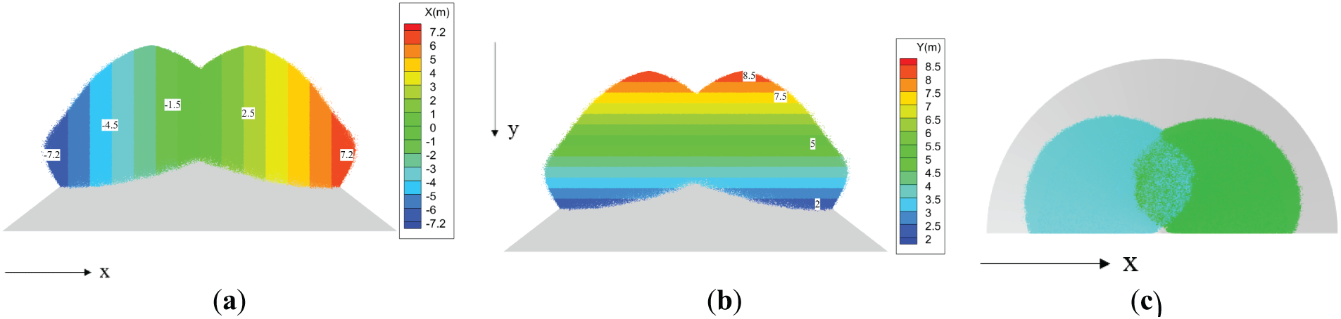
Figure 7: Spread range and overlapping area of droplets at a wind velocity of 2 m/s. (a) Spread range in the x-direction; (b) spread range in the y-direction; (c) overlapping area
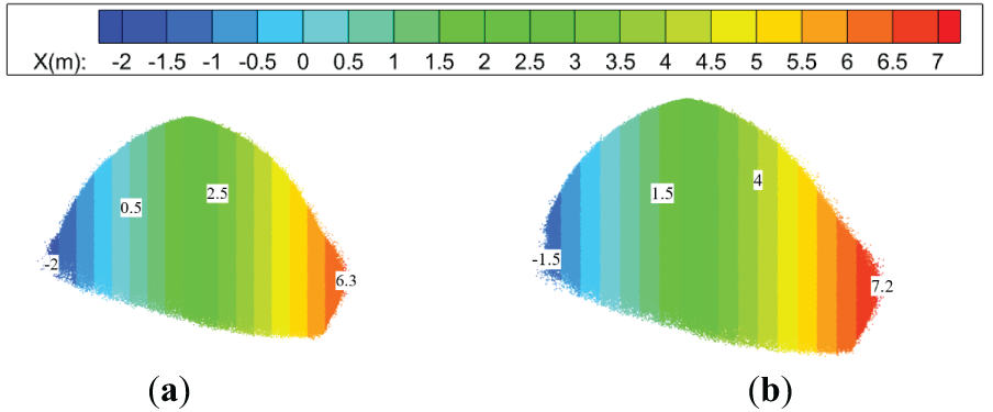
Figure 8: Comparison of droplet spread range in the x-direction for a single nozzle. (a) υ = 0 m/s; (b) υ = 2 m/s
Fig. 9 shows the impact of warehouse temperature and inlet air temperature on the spatial distribution of droplet temperature under h = 1.5 m, θ = 30°, and υ = 2 m/s. A comparison of Figs. 6 and 9 shows that the temperature stratification of the droplets does not change with the wind velocity of 2 m/s, but the temperature at the same layer decreases by approximately 1°C, indicating that the droplet temperature is lower with wind velocity. Additionally, Fig. 9 indicates that when the ambient temperature t∞ drops from 35°C to 30°C, the droplet temperature at two-thirds of the waste pile decreases from 46.5°C to 45.5°C. The above results indicate that the diffusion process and temperature distribution of the atomized droplets are not only influenced by the inlet air velocity but are also closely related to the inlet air temperature. The presence of inlet air velocity not only reduces the overlapping area but, in conjunction with the decrease in inlet air temperature, increases the heat loss of the atomized droplets, thereby reducing the heat exchange efficiency between the droplets and the waste pile. Therefore, to ensure the diffusion process of the atomized droplets and minimize heat, it is recommended to close the unloading door during the heating of the waste pile, which is consistent with operational requirements [29].
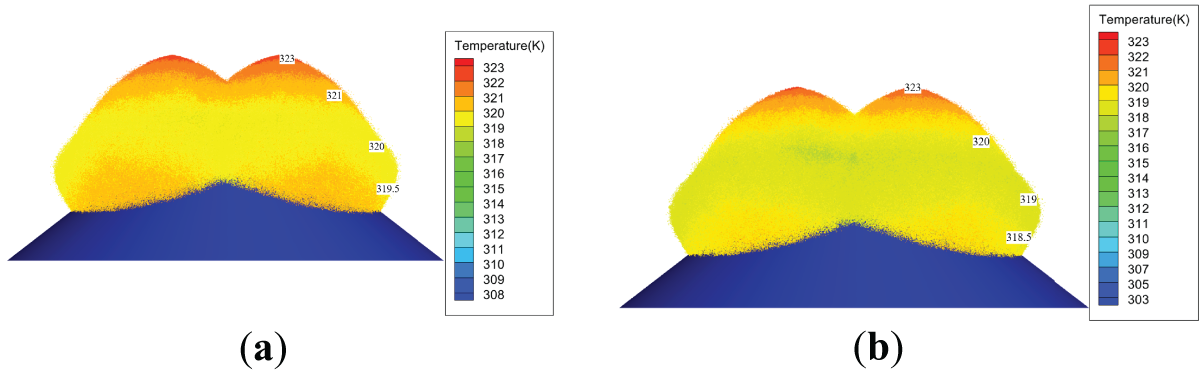
Figure 9: Comparison of droplet temperature distribution under t∞ = 35°C and 30°C at υ = 2 m/s. (a) t∞ = 35°C; (b) t∞ = 30°C
3.3 Droplet Diameter Characteristics
Fig. 10 shows the spatial distribution of atomized droplet diameters under different operating conditions. As shown in Fig. 10, the jet emerging from the nozzle rapidly breaks up and diffuses under high-velocity conditions. The interaction between the droplets at the outer boundary of the jet and the airflow is stronger, leading to a more significant breakup and smaller droplet diameters. In contrast, droplets near the center of the jet section have relatively larger diameters [22–24]. Additionally, under no-wind conditions, droplet breakup and atomization are mainly influenced by injection conditions, and the diameter distribution under different nozzle heights and nozzle angles exhibits high consistency. However, under windy conditions, droplet breakup and atomization are further affected by wind velocity, leading to smaller droplet diameters.
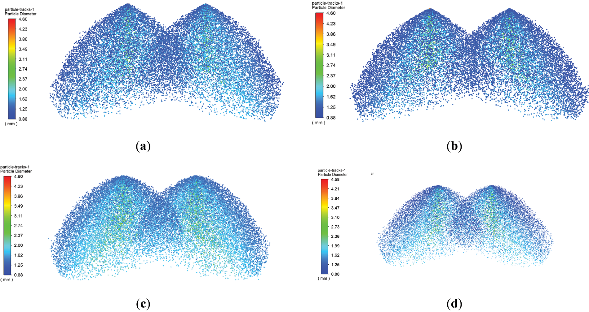
Figure 10: Spatial diameter distribution of atomized droplets under different conditions. (a) υ = 0, θ = 15°, h = 2 m; (b) υ = 0, θ = 15°, h = 1.5 m; (c) υ = 0, h = 1.5 m, θ = 30°; (d) υ = 2 m/s, h = 1.5 m, θ = 30°
Table 3 shows the change in the droplet diameter over time under the conditions of h = 1.5 m, θ = 30°, and no wind velocity. During the period from 0.1 to 0.4 s, the average droplet diameter increased from 1.54 to 1.61 mm. The reason is as follows: in the early stage of atomization, under the influence of gravity and droplet collisions, the smaller atomized droplets re-aggregate, causing an increase in the droplet diameter. Over time, these droplets further break into smaller droplets, leading to a decrease in the average diameter. The variation in the droplet diameter in this study is agreement with conclusions of Nie [30].
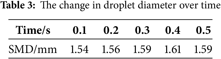
Table 4 compares the maximum, minimum, and average droplet diameters after jet fragmentation under different conditions. It is observed that the effects of nozzle height and nozzle angle are minimal, while the effect of inlet wind speed is relatively significant. Specifically, when υ = 0 and θ = 15°, the average diameter is 1.57 and 1.55 mm for h = 2.0 and h = 1.5 m, respectively. When θ = 30° and 45°, the average diameter increases to 1.56 mm. However, when the inlet wind speed increases to 2 m/s, the average droplet diameter decreases to 1.53 mm at θ = 30°. Although reducing the droplet diameter can improve heat transfer between the droplets and the waste pile, it also increases the temperature drop during the spatial diffusion process, resulting in higher heat loss. This, in turn, hampers the heat exchange efficiency between the droplets and the waste pile.
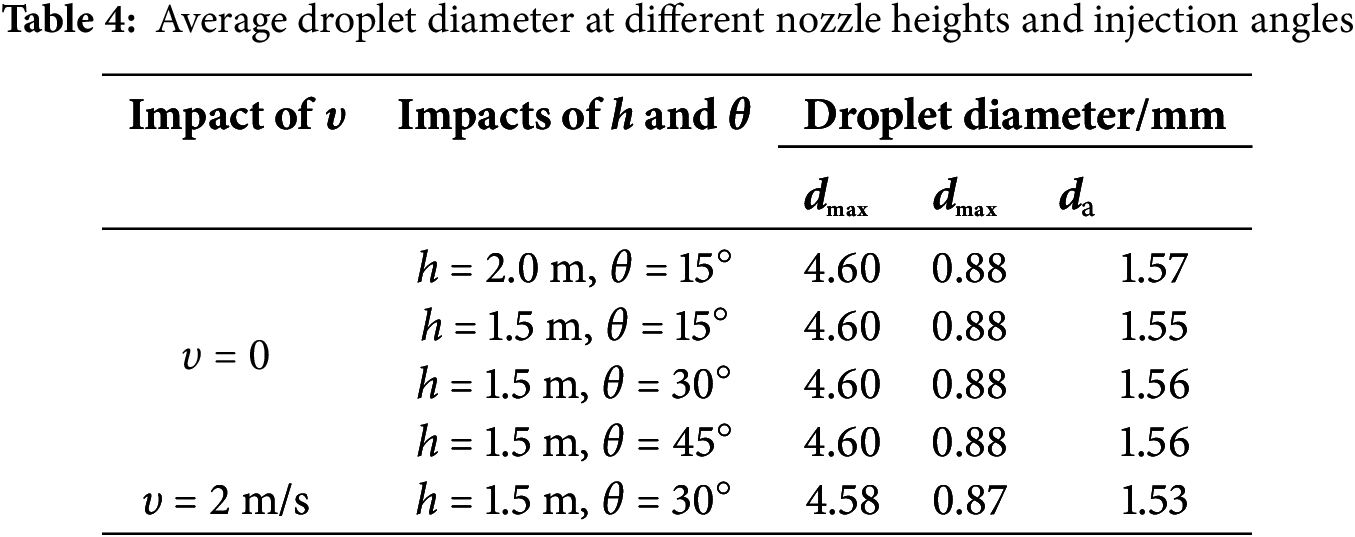
Based on the above analysis, it can be concluded that the optimal performance is achieved when h = 1.5 m and θ = 30°. Therefore, these parameters are recommended as the design specifications for the atomizing nozzle. Additionally, considering the impact of inlet air velocity on the droplet atomization diameter, droplet temperature, and spread area, it is also advised to close the unloading door during the heating of the waste pile.
This study proposes a combined heating method using “hot air injection + dual atomizing nozzles” to improve heating efficiency in waste piles. By introducing atomizing nozzles while maintaining hot air injection temperature, the spread area of atomized droplets can be expanded, reducing their contact time with the waste, thus enhancing heat transfer.
The nozzle height, tilt angle, wind speed at the unloading door, and internal warehouse temperature all impact the droplet diffusion, spread range, temperature, and diameter. Lowering the nozzle height by 0.5 m increases droplet temperature by 1°C and decreases droplet diameter, improving heat transfer. When the warehouse temperature is 35°C, droplets at two-thirds of the waste pile cool from 50°C to 47°C, and at 30°C, they decrease further to 46°C. Adjusting the nozzle tilt angle also influences droplet spread; at a 30° angle, it increases effective coverage and reduces overlapping area, improving heating efficiency.
Increasing wind speed enhances droplet diffusion but reduces overlapping heating areas and droplet size. When the nozzle height is 1.5 m and the angle is 30°, wind speed has minimal effect on overall heating. Based on these findings, it is recommended to use the specified nozzle parameters (h = 1.5 m, θ = 30°) and close the unloading door during heating to optimize heating efficiency.
Acknowledgement: Not applicable.
Funding Statement: The authors received no specific funding for this study.
Author Contributions: Conceptualization: Yan Xiong, Xiangnan Song; Investigation: Jiawei Lu, Lei Liu; Software and methodology: Yaru Yan; Draft manuscript preparation: Yan Xiong, Yaru Yan; Formal analysis: Yaru Yan, Xuemin Ye; Supervision: Yan Xiong, Xiangnan Song; Writing—review & editing: Yaru Yan, Xuemin Ye. All authors reviewed the results and approved the final version of the manuscript.
Availability of Data and Materials: All data and materials used to support the findings of this study are available from the corresponding author upon request.
Ethics Approval: Not applicable.
Conflicts of Interest: The authors declare no conflicts of interest to report regarding the present study.
References
1. Lombardi L, Carnevale E, Corti A. A review of technologies and performances of thermal treatment systems for energy recovery from waste. Waste Manag. 2015;37(41):26–44. doi:10.1016/j.wasman.2014.11.010. [Google Scholar] [PubMed] [CrossRef]
2. Seniunaite J, Vasarevicius S. Leaching of copper, lead and zinc from municipal solid waste incineration bottom ash. Energy Proc. 2017;113(1):442–9. doi:10.1016/j.egypro.2017.04.036. [Google Scholar] [CrossRef]
3. Fitzgerald GC. Pre-processing and treatment of municipal solid waste (MSW) prior to incineration. Waste Energy Convers Technol. 2013;2013(4):55–71. doi:10.1533/9780857096364.2.55. [Google Scholar] [CrossRef]
4. Kamaruddin MA, Lee WS, Norashiddin FA, Hanif MHM, Aziz HA, Wang LK, et al. Treatment and management of hazardous solid waste stream by incineration. In: Waste treatment in the bio-technology, agricultural and food industries. Vol. 2. Berlin/Heidelberg, Germany: Springer; 2023. p. 285–335. [Google Scholar]
5. Marieta C, Guerrero A, Leon I. Municipal solid waste incineration fly ash to produce eco-friendly binders for sustainable building construction. Waste Manag. 2021;120(3):114–24. doi:10.1016/j.wasman.2020.11.034. [Google Scholar] [PubMed] [CrossRef]
6. Chen GY, Li XG, Gao Y. Discussion on the composting fermentation and dehydration of domestic waste in winter in northern China. Environ Sanit Eng. 2019;27(4):32–4. (In Chinese). doi:10.3969/j.issn.1005-8206.2019.04.008. [Google Scholar] [CrossRef]
7. Burns C, Orttung RW, Shaiman M, Silinsky L, Zhang E. Solid waste management in the Arctic. Waste Manag. 2021;126(10):340–50. doi:10.1016/j.wasman.2021.03.021. [Google Scholar] [PubMed] [CrossRef]
8. Singh M, Gupta A, Yadav K, Jain K, Shrivastava P, Seth RK, et al. Co-combustion properties of torrefied rice straw-sub-bituminous coal blend and its Hardgrove Grindability Index. Biomass Convers Biorefin. 2023;13(8):6647–61. doi:10.1007/s13399-021-01696-3. [Google Scholar] [CrossRef]
9. Choo H, Kim YG, Kim D. Power sector carbon reduction review for South Korea in 2030. Renew Sustain Energy Rev. 2024;196(5):114348. doi:10.1016/j.rser.2024.114348. [Google Scholar] [CrossRef]
10. Jouhara H, Czajczyńska D, Ghazal H, Krzyżyńska R, Anguilano L, Reynolds AJ, et al. Municipal waste management systems for domestic use. Energy. 2017;139(4):485–506. doi:10.1016/j.energy.2017.07.162. [Google Scholar] [CrossRef]
11. Adetunji AI, Oberholster PJ, Erasmus M. From garbage to treasure: a review on biorefinery of organic solid wastes into valuable biobased products. Bioresour Technol Rep. 2023;24:101610. doi:10.1016/j.biteb.2023.101610. [Google Scholar] [CrossRef]
12. Yaashikaa PR, Kumar PS, Nhung TC, Hemavathy RV, Jawahar MJ, Neshaanthini JP, et al. A review on landfill system for municipal solid wastes: insight into leachate, gas emissions, environmental and economic analysis. Chemosphere. 2022;309(Pt 1):136627. doi:10.1016/j.chemosphere.2022.136627. [Google Scholar] [PubMed] [CrossRef]
13. Nanda S, Berruti F. Municipal solid waste management and landfilling technologies: a review. Environ Chem Lett. 2021;19(2):1433–56. doi:10.1007/s10311-020-01100-y. [Google Scholar] [CrossRef]
14. Luo CJ, Qian B, Li J. Design for waste bunker heating system in MSW incineration power generation plant. China Environ Prot Ind. 2018;10:71–2. (In Chinese). doi:10.3969/j.issn.1006-5377.2018.10.018. [Google Scholar] [CrossRef]
15. Khan O, Parvez M, Yahya Z, Alhodaib A, Yadav AK, Hoang AT, et al. Waste-to-energy power plants: multi-objective analysis and optimization of landfill heat and methane gas by recirculation of leachate. Process Saf Environ Prot. 2024;186(104):957–68. doi:10.1016/j.psep.2024.04.022. [Google Scholar] [CrossRef]
16. Zhang D, Jiang YZ, Li HR, Bai JH, Zhang R. Research progress in biomass coupling cogeneration systems for cooling, heating, and electricity. Trans Chin Soc Agric Eng. 2024;40(4):14–28. doi:10.11975/j.issn.1002-6819.202309215. [Google Scholar] [CrossRef]
17. Wang ZM, Hong G. Research on waste bunker heating scheme for MSW incineration power plant in winter. China Environ Prot Ind. 2020;(6):69–72. (In Chinese). doi:10.3969/j.issn.1006-5377.2020.06.015. [Google Scholar] [CrossRef]
18. Wang LK, Wang MH, Cardenas RR, Sabiani NH, Yusoff MS, Hassan SH, et al. Composting processes for disposal of municipal and agricultural solid wastes. In: Solid waste engineering and management. Vol. 1. Berlin/Heidelberg, Germany: Springer; 2021. p. 399–523. [Google Scholar]
19. Kazemi Seresht S, Mohammadi A. Liquid fuel distribution in the combustion chamber by jet impingement on small cylindrical obstacles. Fuel. 2021;304(4):121387. doi:10.1016/j.fuel.2021.121387. [Google Scholar] [CrossRef]
20. Guo JP, Wang YB, Bai FQ, Du Q. Unstable breakup of a power-law liquid fuel jet in the presence of a gas crossflow. Fuel. 2020;263(11):116606. doi:10.1016/j.fuel.2019.116606. [Google Scholar] [CrossRef]
21. Shams Ghahfarokhi P, Podgornovs A, Kallaste A, Marques Cardoso AJ, Belahcen A, Vaimann T. The oil spray cooling system of automotive traction motors: the state of the art. IEEE Trans Transp Electrif. 2023;9(1):428–51. doi:10.1109/TTE.2022.3189596. [Google Scholar] [CrossRef]
22. Wu ZR, Wu QD, Xiao H, Yang X, Li Y. Influencing factors of atomization characteristics and droplet diameter distribution of nozzle groups. J Jinan Univ (Nat Sci Ed). 2022;36(6):741–7. doi:10.13349/j.cnki.jdxbn.20220720.002. [Google Scholar] [CrossRef]
23. Wu ZR, Shi YW, Peng ZC, Yang XN, Liu M. Numerical simulation of atomization characteristics of dual-medium nozzle. Packag Eng. 2023;44(15):184–93. doi:10.19554/j.cnki.1001-3563.2023.15.024. [Google Scholar] [CrossRef]
24. Liu Y, Ye XM, Yang TK, Li CX. Numerical study on droplet breakage and particle distribution in rotating nebulizers. Electr Power Sci Eng. 2023;39(4):69–78. doi:10.3969/j.ISSN.1672-0792.2023.04.008. [Google Scholar] [CrossRef]
25. Shrigondekar H, Chowdhury A, Prabhu SV. Performance by various water mist nozzles in extinguishing liquid pool fires. Fire Technol. 2021;57(5):2553–81. doi:10.1007/s10694-021-01130-0. [Google Scholar] [CrossRef]
26. Tong J, Zhang Y, Wu R, Qi X, Ye X. Investigation of the effects of a large percentage of dried sludge on the operation of a coal-fired boiler. Fluid Dyn Mater Process. 2023;19(4):1027–41. doi:10.32604/fdmp.2022.022303. [Google Scholar] [CrossRef]
27. Sai H. Development of nozzle technology and new nozzle techniques. Beijing Energy Conserv. 1996;5:20–1. (In Chinese). [cited 2025 Feb 20]. Available from: https://qikan.cqvip.com/Qikan/Article/Detail?id=2328301. [Google Scholar]
28. Yao BD, Jiang JB, Lan QM, Zhang ZX. Researches and progress on the spray nozzles for wet FGD. Chem Eng Mach. 2006;33(4):194–7. (In Chinese). doi:10.3969/j.issn.0254-6094.2006.04.002. [Google Scholar] [CrossRef]
29. Fan CP, Zheng SW, Xing YM. Harm and prevention measures of frozen waste for waste incineration plant in alpine region. Environ Sanit Eng. 2013;21(4):39–40. (In Chinese). doi:10.3969/j.issn.1005-8206.2013.04.015. [Google Scholar] [CrossRef]
30. Nie HY. Numerical simulation on atomization progress of swirl nozzle jet [master’s thesis]. Harbin, China: Harbin Engineering University; 2020. (In Chinese). doi:10.27060/d.cnki.ghbcu.2020.000735. [Google Scholar] [CrossRef]
Cite This Article
 Copyright © 2025 The Author(s). Published by Tech Science Press.
This work is licensed under a Creative Commons Attribution 4.0 International License , which permits unrestricted use, distribution, and reproduction in any medium, provided the original work is properly cited.
 Downloads
 Citation Tools