
 Submit a Paper
 Propose a Special lssue
 Open Access
ARTICLE

Numerical Analysis of Mooring System Hydrodynamics under Irregular Wave Conditions
College of Mathematics and System Sciences, Xinjiang University, Urumqi, 830017, China
* Corresponding Author: Azhar Halik. Email:
(This article belongs to the Special Issue: Advances in Theoretical and Applied Wave Hydrodynamics)
Fluid Dynamics & Materials Processing 2025, 21(8), 1969-2000. https://doi.org/10.32604/fdmp.2025.067813
Received 13 May 2025; Accepted 14 July 2025; Issue published 12 September 2025
 View Full Text
 Download PDF
Abstract
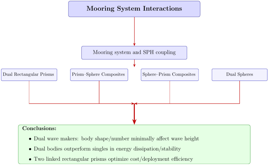
This study employs the Smoothed Particle Hydrodynamics (SPH) method to develop a computational fluid dynamics (CFD) model for analyzing the interaction between rogue waves and mooring systems. Four floating body configurations are investigated: (1) dual rectangular prisms, (2) rectangular prism–sphere composites, (3) sphere–rectangular prism composites, and (4) dual spheres. These configurations are systematically evaluated under varying mooring conditions to assess their hydrodynamic performance and wave attenuation capabilities. The model accurately captures the complex fluid–structure interaction dynamics between moored floating breakwaters and incident wave fields. Among the configurations, the dual rectangular prism system demonstrates superior performance in both wave dissipation and mooring force reduction. Under conditions involving dual wave makers, the influence of floating body shape and number on wave height is found to be minimal. However, dual-body arrangements consistently outperform single-body setups in terms of both energy dissipation and structural stability. From a cost-efficiency perspective, the configuration comprising two rectangular prisms connected via a single mooring system offers significant advantages in material usage and deployment feasibility.Graphic Abstract
Keywords
Rogue waves are highly nonlinear, asymmetrical ocean waves with abnormally large heights, typically exceeding 2.0 to 2.2 times the significant wave height [1]. These waves concentrate their energy and momentum in localized areas through short wave sequences, posing significant threats to marine structures. Various hypotheses have been proposed to explain their formation, but no scientific consensus has been reached. Onorato et al. [2] suggested that the generation of rogue waves varies under different physical conditions. Pelinovsky and Kharif [3] proposed mechanisms such as dispersive focusing and Benjamin-Feir instability. Experiments have shown that increased wave steepness due to positive current gradients can induce modulational instability, leading to large-amplitude waves. Jeon et al. [4] simulated a bull’s-eye wave generated by multi-directional wave focusing. Using the open-source software OpenFOAM 5.0, they developed a multi-directional wave generation boundary condition. This enabled them to investigate the water particle kinematics on the free surface of rogue waves and study their impact on floating structures.
Breakwaters are marine structures that protect harbor areas from wave-induced damage and are crucial for port protection. Floating breakwaters, in particular, are gaining increasing global attention. They are well-suited for deep-water conditions, soft seabed foundations, and large tidal ranges. Additionally, they can facilitate water exchange to improve harbor water quality.
In recent years, researchers have explored and evaluated different types of breakwaters to meet diverse environmental needs, such as traditional bottom-mounted and floating breakwaters. Traditional bottom-mounted breakwaters are highly effective at reflecting and absorbing waves, but they require a large volume of construction materials and can restrict water exchange. In contrast, floating breakwaters are widely used for wave reduction and offer several environmental benefits. They promote better water circulation in nearshore areas and are suitable for offshore or coastal regions with weak seabed conditions. Floating breakwaters also have less stringent seabed foundation requirements, lower costs, and quicker installation times. With improvements in data collection and computer technology, computational fluid dynamics (CFD) has enabled detailed studies of the hydrodynamic performance of floating breakwaters [5]. These advantages have attracted significant interest from researchers and engineers.
Floating breakwaters exist in several forms, such as single-pontoon, double-pontoon, mat-type, and horizontal-plate designs [6]. The single-pontoon type has been more widely studied due to its simple structure. Ren et al. [7] developed an SPH model to simulate the nonlinear interactions between waves and floating breakwaters (FBs). After verifying the numerical model, they examined how structural length and density affect the hydrodynamic performance of FBs. Liu and Wang [8] used DualSPHysics to numerically study the hydrodynamics of moored single-pontoon floating breakwaters with six cross-sectional shapes: circular, downward-triangular, upward-triangular, rectangular, downward-trapezoidal, and upward-trapezoidal. Chen et al. [9] carried out thorough numerical and experimental research on the hydrodynamic characteristics of double-pontoon floating breakwaters. Their findings showed that double-pontoon designs outperform single-pontoon breakwaters in wave attenuation.
Floating breakwaters typically utilize one of three mooring systems [6,10]: taut, slack, or hybrid. Taut mooring systems employ pre-tensioned metal wires or fiber ropes that are held under tension. Since the tension is much greater than the rope’s weight, the mooring force mainly arises from the stretching of the lines. Slack mooring systems use heavy, long chains that hang naturally in the water. Here, the mooring force is primarily due to the catenary effect and weight of the submerged chain. Hybrid mooring systems attach the floating structure to steel pipes driven into the seabed. In this setup, the main force on the floater is the horizontal wave force, as the floater tends to lift along the piles. When developing and using different floating breakwaters, it is crucial to accurately quantify the forces on the breakwater and its mooring lines, as well as the dynamic response of the entire floating breakwater system.
SPH is a gridless, or mesh-free, method for simulating fluid dynamics. The method operates by tracking a multitude of discrete particles that represent the fluid domain. In the software DualSPHysics, SPH is implemented with three main components: the basic SPH formulation, a density diffusion term added by Molteni and Colagrossi, and a particle shifting technique (PST) to maintain a regular particle distribution [11,12]. The Molteni and Colagrossi term can sometimes cause numerical instabilities near the fluid surface; consequently, an improved formulation was developed to address this issue. This new formulation ensures robust performance throughout the fluid domain, particularly near the surface, leading to a new set of governing equations that incorporate diffusion in both the fluid’s momentum and energy, characterizing the natural fluid behavior [13]. In recent years, mesh-free methods have gained popularity. SPH is a prominent example, widely used in engineering due to its distinct advantages. Unlike grid-based methods, SPH does not require a structured mesh for computation. This characteristic makes it particularly effective for modeling large deformations of the fluid domain.
SPH is a robust method for simulating free-surface flows and intense wave-structure interactions, as the free surface does not require special tracking algorithms. Its meshless nature allows it to handle large free-surface deformations without concerns about grid distortion. Additionally, SPH can readily handle moving complex boundaries, floating bodies, and fluid interfaces. In recent years, there have been major improvements in SPH, especially in the development of
Moreover, SPH is inherently well-suited for tracking free surfaces and moving boundaries, a key feature of the method. However, SPH also has challenges, such as high computational costs. Recently, DualSPHysics, which is based on SPHysics, has been developed. It includes a graphical user interface tool for practical engineering problems. DualSPHysics is physics-based and can be executed on GPUs, leveraging powerful parallel computing to significantly reduce simulation time.
Rogers et al. [16] employed the open-source code SPHysics to simulate the stability of caisson breakwaters. Barreiro et al. [17] simulated wave-structure interactions in a case study of wave forces on coastal urban structures. Vacondio et al. [18] simulated 3D waves generated by rock slides on rubble mound breakwaters. Altomare et al. [19] used the DualSPHysics software package to study wave run-up on rubble mound breakwaters [20]. An improved relaxation zone technique was proposed to avoid the influence of reflected waves in the DualSPHysics model. This numerical approach for assessing wave forces on coastal structures was validated, and the improved relaxation zone technique was proposed to mitigate reflected wave effects in DualSPHysics simulations. The SPH-based DualSPHysics model has been successfully applied to other engineering challenges, including floating structure dynamics under wave propagation, liquid-sediment multiphase scour, and flow-induced resuspension phenomena [21–24]. Therefore, DualSPHysics has been demonstrated to be an effective tool for the preliminary design of coastal defenses. This review of the literature provides a preliminary understanding of the formation mechanisms and relevant aspects of rogue waves and floating breakwaters, which offers a valuable foundation for our future research.
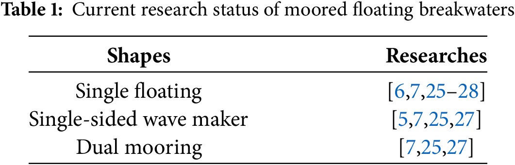
Table 1 summarizes the current research status of moored floating breakwaters. However, to the authors’ knowledge, few systematic comparisons exist regarding the wave height and floating body position changes for floating breakwaters with dual wave-generating panels, single and dual mooring systems, and dual floating bodies.
The first innovation of this study is the analysis of dual floating structures with various configurations connected by a mooring system. We investigate the displacement variations of the floating structures under severe wave conditions generated by dual wave-making panels. Comparisons are made regarding the wave height and positional changes of the dual floating structures under different mooring configurations and single/dual wave-making panels. The second innovation involves the development of a program that extracts time-series data of wave height at specific surface points, vertical displacements of the floating bodies, and their three degrees of freedom. The structure of this paper is as follows: Section 2 introduces the basic concepts and principles of the SPH method; Section 3 presents validation cases of wave interaction with floating breakwaters; Section 4 contains significant numerical simulations and the core research content; and Section 5 summarizes the main conclusions.
This section outlines the SPH approach and mooring systems, combining them into a coupled SPH-mooring framework. DualSPHysics models the fluid-breakwater interactions, whereas Moordyn handles the mooring line dynamics.
This research utilizes an open-source mooring analysis tool grounded in lumped-mass theory to determine mooring forces for floating structures [29]. For modeling free-surface flows, the study implements DualSPHysics (https://dual.sphysics.org/) (accessed on 13 July 2025), a well-established SPH framework optimized for GPU acceleration. The combined approach enables precise simulation of wave-breakwater interactions, benefiting from both computational efficiency and numerical stability. While leveraging existing open-source solutions, the following sections outline the essential simulation methodologies.
2.1 Particle-Based Equations in SPH
SPH is a mesh-free Lagrangian technique well-adapted for simulating free-surface flows and wave dynamics. This method represents the fluid using discrete, independent material particles. Before presenting the governing equations of SPH, it is essential to address a key principle: the conservation laws from continuum fluid mechanics must be converted from their partial differential form into a particle-based framework. This transformation is accomplished by employing integral equations and interpolation functions that enable computation at individual particle positions. The interpolation function, or kernel function W, can assume various mathematical forms. This study employs the quintic kernel function for all simulations [30]:
where
In the SPH method, fluid regions are discretized into a set of particles. The physical quantities of each particle, such as position and velocity, are calculated by interpolating these values from neighboring particles. The core of the SPH method is the interpolation scheme, which allows for the approximation of any field function F through integral calculations, as shown below:
where
where
where
The conservation laws of continuum fluid dynamics can be expressed in this form, thereby yielding the SPH governing equation (Eq. (4)). Assuming that the fluid is discretized into N particles, the choice of the number of particles depends on the accuracy requirements of the simulation and the available computational resources. Generally, a higher number of particles leads to more accurate simulations, albeit at a higher computational cost.
Given the total volume of the fluid as V and the number of particles as N, the volume of each particle
The motion of fluid particles is governed by the momentum equation and the equation of mass continuity, refer to the study by Crespo et al. [31] as shown below:
here,
2.2 Motion of Floating Objects
The motion model of the floating body is shown in Fig. 1. According to Newton’s second law, the equations of motion can be written as:
the dynamic behavior of the floating body is governed by its linear velocity
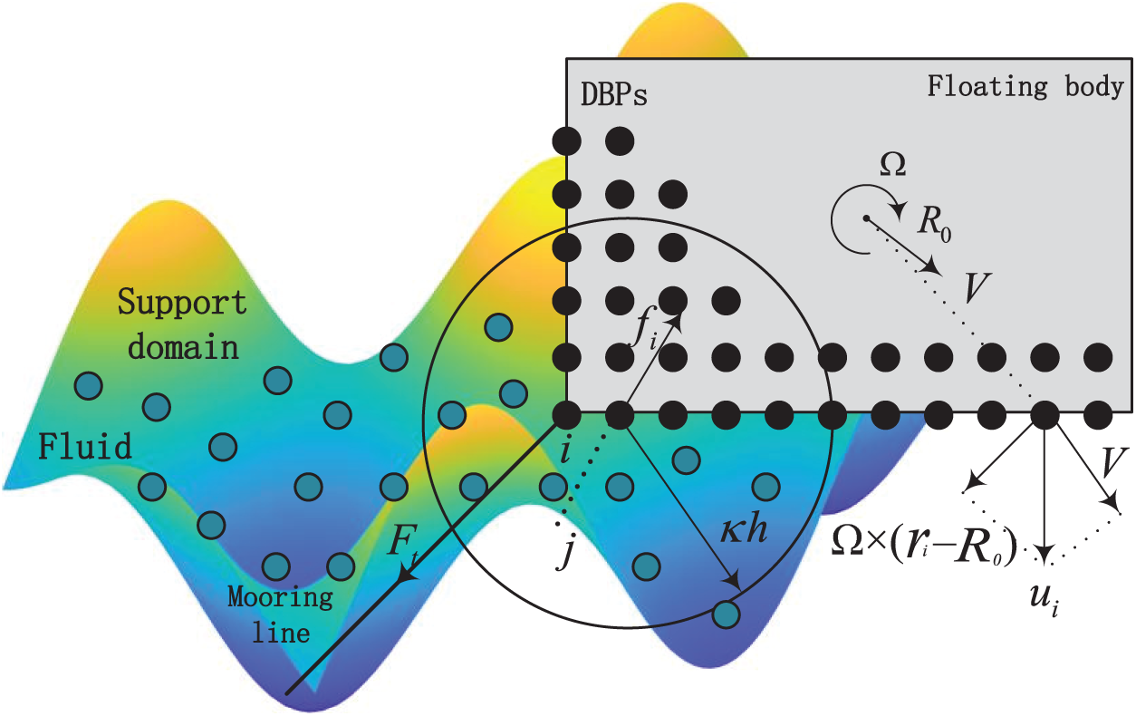
Figure 1: Sketch of the motion model of the floating body
Adopting the simplified spring analogy [30], the analysis disregards mooring line mass and gravitational effects. System equilibrium in still water is achieved through cable pretension, generating a mooring force:
the mooring line pretension
The moment exerted on the floating body by the mooring cable is:
where
The moment exerted by force
consequently, the total wave force and the force acting on the floating body are calculated by the formulas in Eqs. (13) and (14) as follows:
The numerical implementation successfully integrated DualSPHysics with Moordyn, establishing a fully coupled SPH-mooring simulation framework. The DualSPHysics solver performs three primary computational functions: (1) an efficient neighbor-particle search using a cell-linked list, (2) an iterative solution of the particle governing equations, and (3) temporal advancement of physical quantities using a suitable time-stepping scheme. This coupled modeling approach builds upon previous successful implementations of floating breakwater-mooring system interactions, as demonstrated in the works of Domínguez et al. [23] and Liu et al. [32].
A loosely coupled scheme is employed at each time step [33], where each computational step sequentially performs the SPH-based hydrodynamic force calculation on the floating breakwater, transfers the structural kinematics data to Moordyn, solves the mooring line dynamics, and finally feeds the resultant forces back to DualSPHysics for breakwater motion computation. This partitioned approach maintains proper synchronization between fluid-structure interaction and mooring dynamics, with the complete workflow illustrated in Fig. 2.
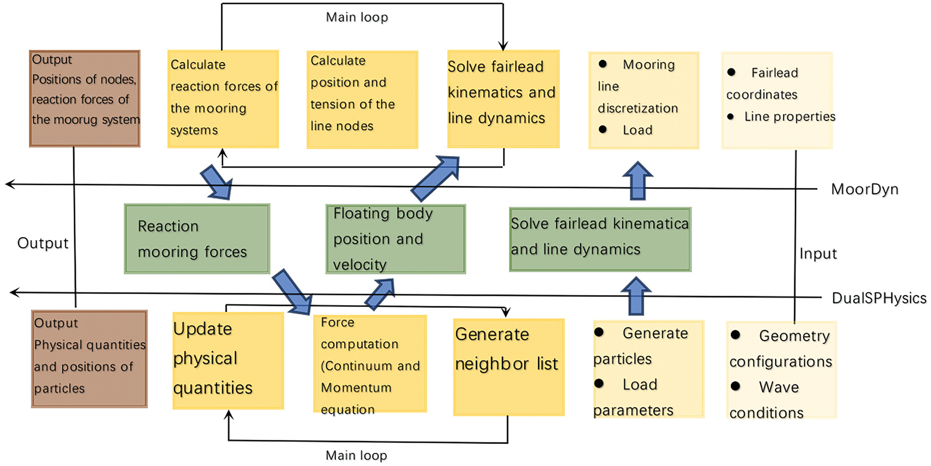
Figure 2: A sketch of the coupling procedure between the SPH model and the mooring analysis program
This study presents an integrated numerical framework that combines CFD with a coupled mooring system algorithm to simulate wave-structure interactions. The methodology employs smoothed particle hydrodynamics to establish the numerical wave tank, incorporating a novel mooring dynamics module through customized programming within the SPH solver. The approach accurately captures floating body motions and associated mooring tensions under regular wave conditions.
3 Validation of SPH Mooring Model
This section validates the SPH-based hydrodynamic model by simulating wave-floating body interactions. The simulation results are systematically validated against experimental data reported in previous [5] and [7], demonstrating the model’s accuracy in capturing complex fluid-structure interaction phenomena.
3.1.1 Numerical Wave Tank Setup
The first validation case is based on the experimental configuration from Ren et al. [7], which consists of a 2D wave flume with distinct boundary conditions: a piston-type wave generator at the left boundary and an inclined beach (
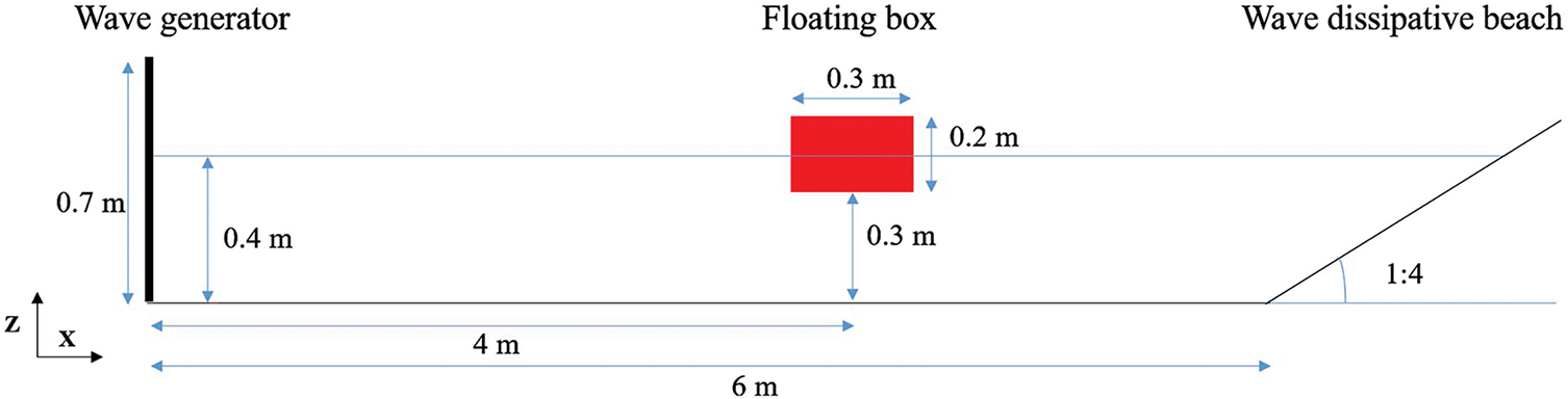
Figure 3: Numerical setup of the experiment forced by regular waves
3.1.2 Comparative Analysis between Physical Experiments and Numerical Simulations
The study focuses on analyzing the variation of wave surface elevation over time in the absence of a floating box, as well as the three-degree-of-freedom motions (surge, heave, and pitch) of an unconstrained floating box under regular wave conditions (H = 0.1 m, T = 1.2 s). The numerical simulations employ three particle spacings: dp = 0.015 m, dp = 0.01 m, and dp = 0.005 m. The SPH model accurately predicts the undisturbed water level elevation (
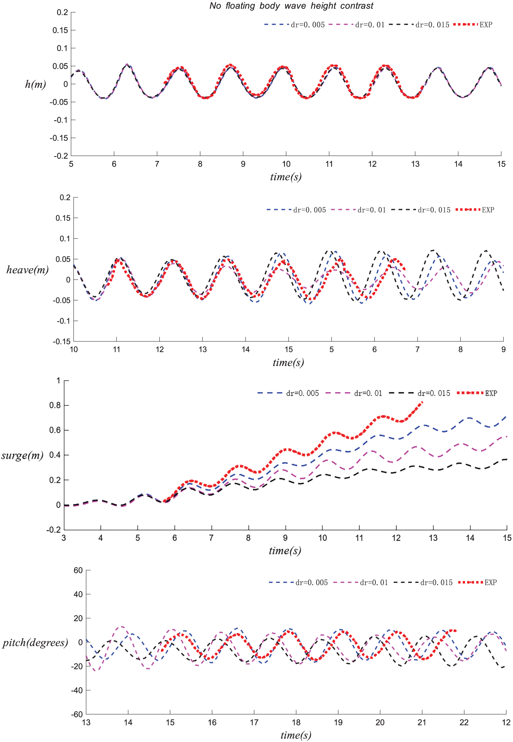
Figure 4: The comparison of the experimental and numerical time series of the water level (
3.2.1 Numerical Wave Tank Setup
The second validation case is based on the SPH simulation and experimental setup from Jeon et al. [4], as depicted in Fig. 5. The incident wave conditions are defined by a wave height (H) of 0.15 m and a period (T) of 1.2 s. For this scenario, the experiment was conducted in a 2D wave tank at Jiangsu University of Science and Technology, with a scale ratio of 1:20. The wave tank is 40 m (length)
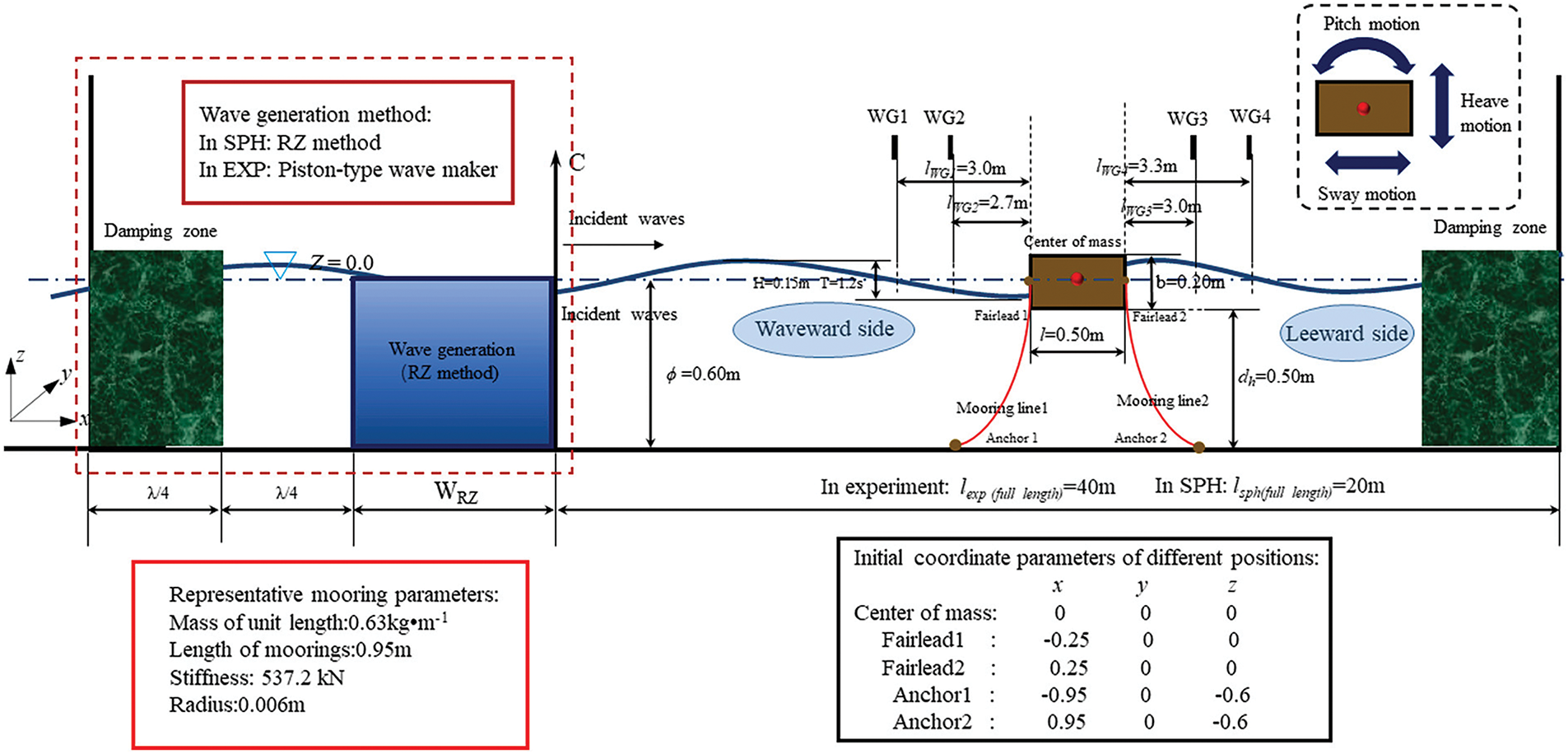
Figure 5: A sketch of verification case for a moored floating breakwater
3.2.2 Comparative Analysis between Physical Experiments and Numerical Simulations
In this validation, four numerical wave gauges (WG1–WG4) were used to measure water levels at different locations, thereby capturing the spatio-temporal dynamics of the wave field. Fig. 6 provides a detailed comparison of the time histories between the SPH simulation and physical experiments, which was used to validate the accuracy of the numerical simulation method. With a particle spacing of dp = 0.008 m, the numerical solution was compared with the experimental values. The results demonstrate that the coupled SPH method can accurately predict the wave height, with the numerical solution closely matching the experimental data, particularly in capturing wave crests and troughs. This validation further confirms the reliability and effectiveness of the coupled SPH method in simulating wave propagation and wave height variation, providing a solid foundation for subsequent studies on wave-structure interactions.
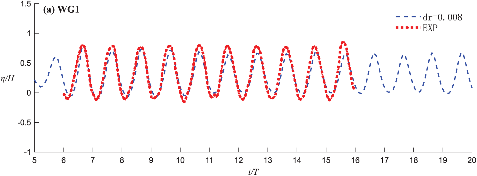
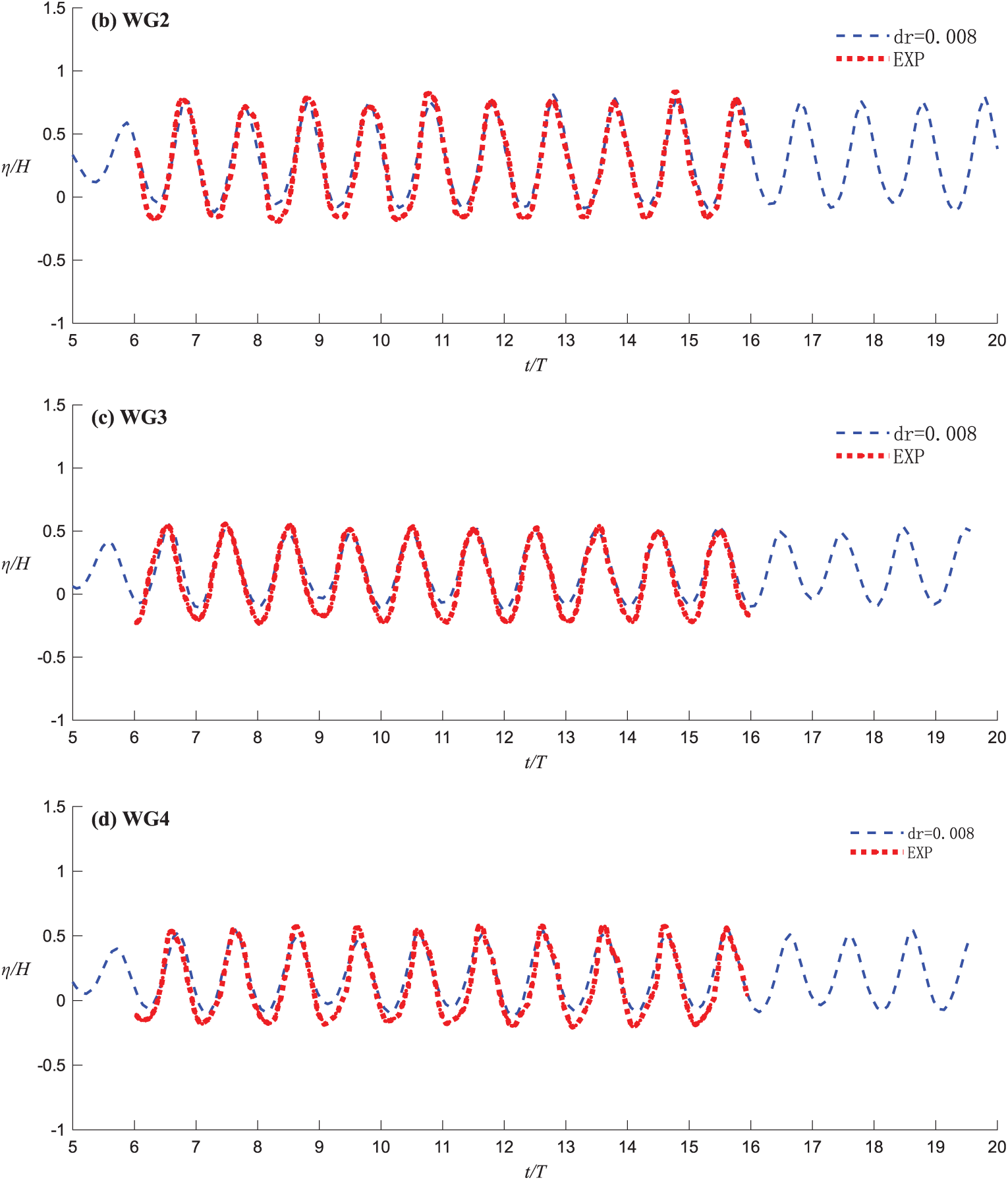
Figure 6: Comparisons of the time histories of the water elevations at (a) WG1, (b) WG2, (c) WG3 and (d) WG4 for experiments and SPH simulation. The horizontal and vertical axes are normalized by T and H
4.1 Basic Setup of Dual Floating Breakwaters
A 2D numerical model is used for this study. This study employs a piston-type numerical wave paddle to generate the specified wave conditions, which can produce both regular non-breaking and breaking waves under appropriate circumstances. The numerical model setup is shown in Fig. 7, which depicts a 2D wave tank with a length of 32 m and a height of 1.5 m. The wave conditions are defined by an incident wave height (H) of 0.1 m and a period (T) of 1 s. Geometric details of the 2D model and the four considered floating body configurations are shown in the figures (Fig. 8).
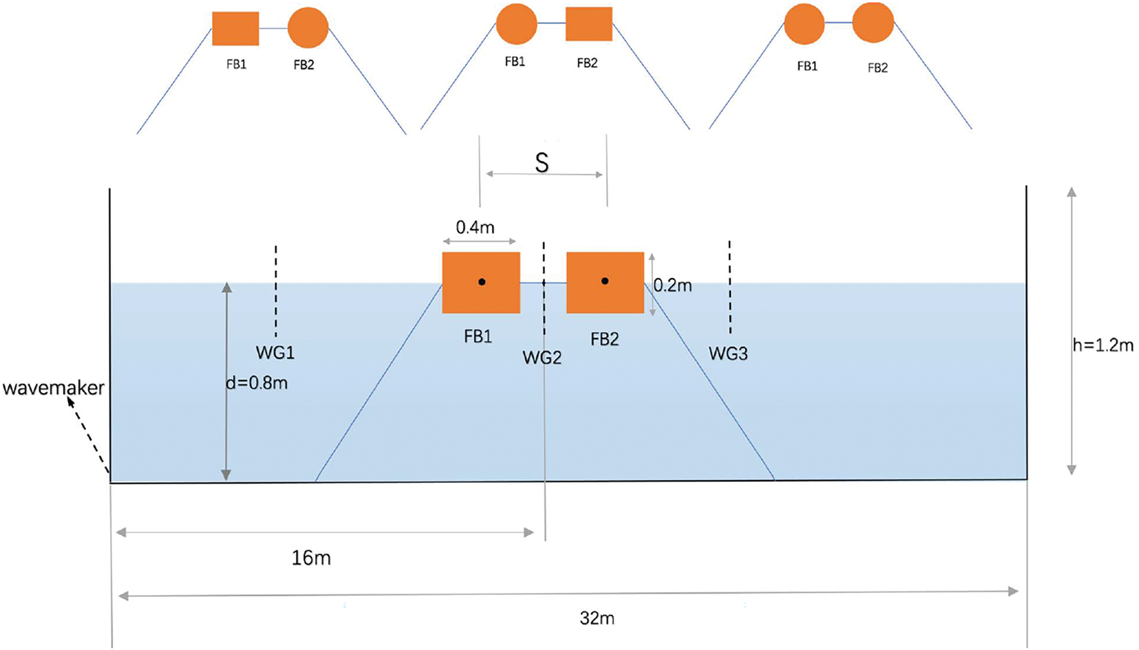
Figure 7: Schematic diagram of the numerical water tank for the double floating breakwater in Case 1
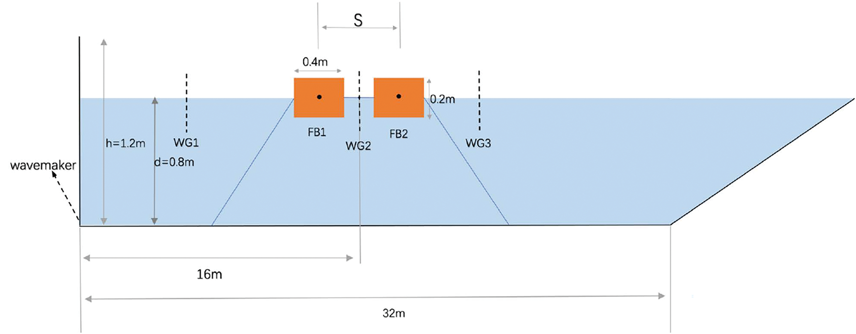
Figure 8: Schematic diagram of the numerical water tank for the double floating breakwater in Case 1´
The simulation cases are defined as follows: Case 1 (dual wave maker, dual mooring); Case 1´ (single wave maker, dual mooring); Case 2 (dual wave maker, single mooring); Case 2´ (single wave maker, single mooring); Case 3 (dual wave maker, dual connected floating bodies); Case 3´ (single wave maker, single connected floating body); Case 4 (dual wave maker, single floating body); and Case 4´ (single wave maker, single floating body). Cases 1, 1´, 2, 2´, 3, and 3´ are set with four model configurations (SS, SC, CS, CC), while Cases 4 and 4´ are set with two model configurations (S and C). The relevant parameters can be seen in the following Tables 2–5.
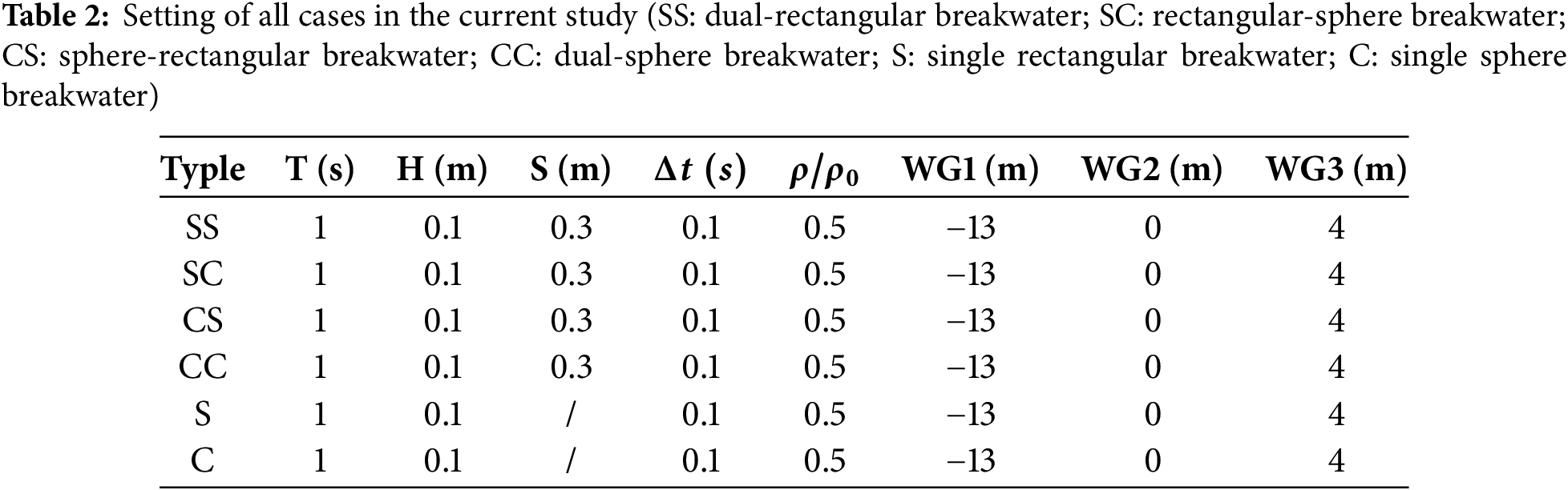
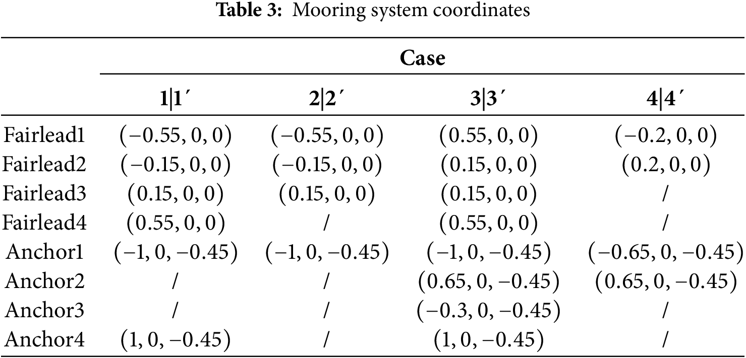
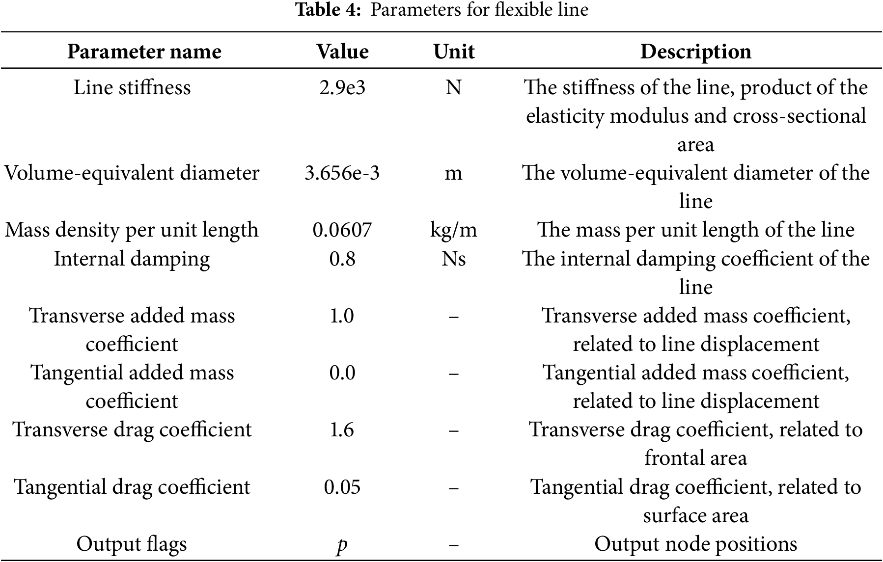
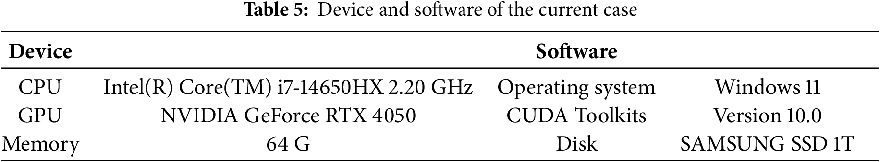
Fig. 9 illustrates the velocity field around a dual-connected rectangular breakwater (SS) in the case of dual wave makers (Case 1). The simulation uses a wave period of T = 1 s and a particle spacing of dp = 0.01 m. A complete wave cycle is depicted, ranging from t = 25 s to 26 s, during which the full cycle of the pitch motion can be observed. The color of the particles corresponds to the magnitude of their velocity, and the arrows indicate the direction of velocity.
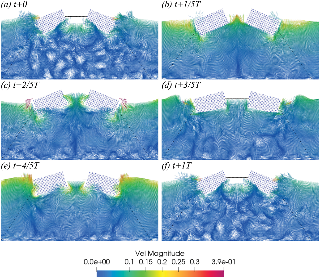
Figure 9: In Case 1, the velocity vector diagram of the SS configuration within a one-period interval starting at t = 25 s (T = 1 s, H = 0.1 m) (a–f)
Fig. 10 presents the time histories of wave elevation at three observation points (x = −13 m, x = 0 m, and x = 4 m, denoted as WG1, WG2, and WG3) for the four dual-body configurations under dual wave maker conditions. Overall, the wave height profiles are broadly similar across the four configurations. At positions far from the floating bodies, the wave heights almost coincide with those in the absence of floating bodies. However, the motion of the floating bodies generates radiated waves that can superimpose on the incident waves. At the center (x = 0 m), constructive interference between the waves from the dual wave makers and the radiated waves from the bodies leads to significantly amplified wave heights. For the dual wave maker setup, the influence of the four body configurations on wave height is minimal.
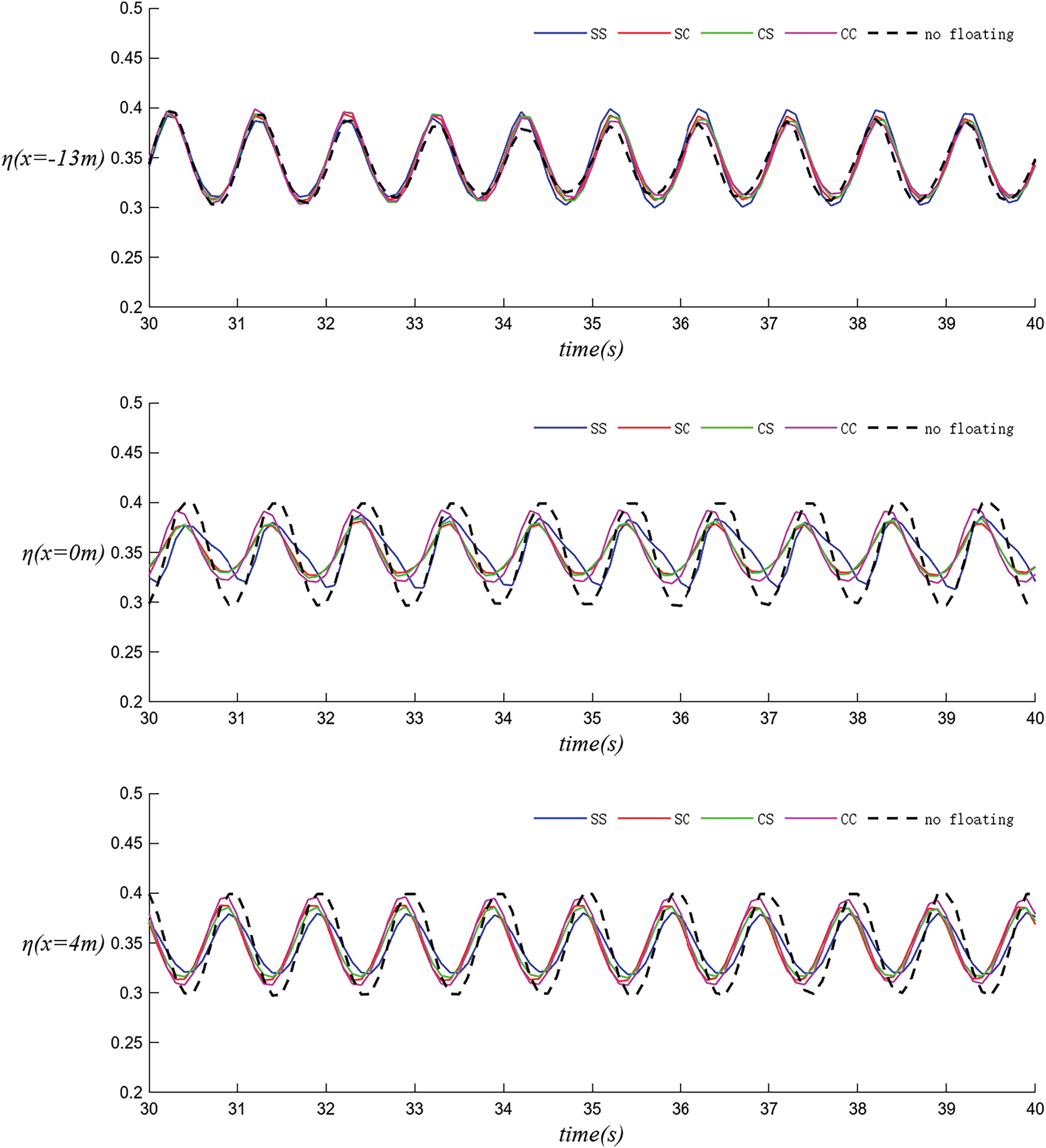
Figure 10: In Case 1, SS, SC, CS, and CC are compared in terms of their water level time histories in WG1, WG2 and WG3
Fig. 11 illustrates the three-degree-of-freedom motion of the breakwater’s floating bodies under standard conditions with different configurations, where FB1 represents the left floating body and FB2 represents the right floating body. Since the simulated wave tank is symmetrical about the central connection line of the dual floating bodies, the motions of the left and right bodies are nearly identical for the symmetric SS and CC configurations, whereas they are opposed for the asymmetric SC and CS configurations.
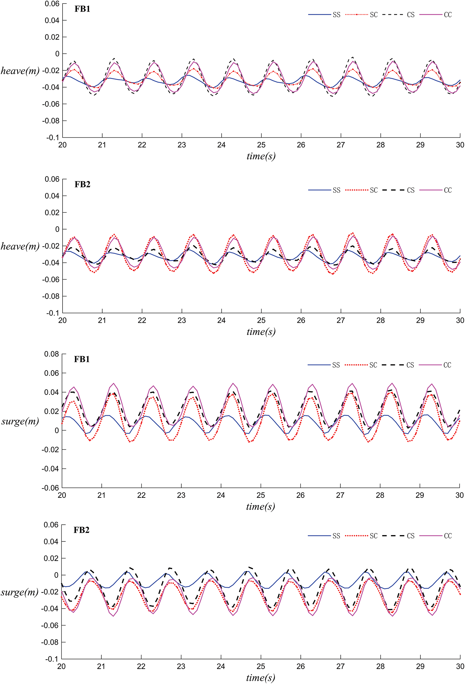
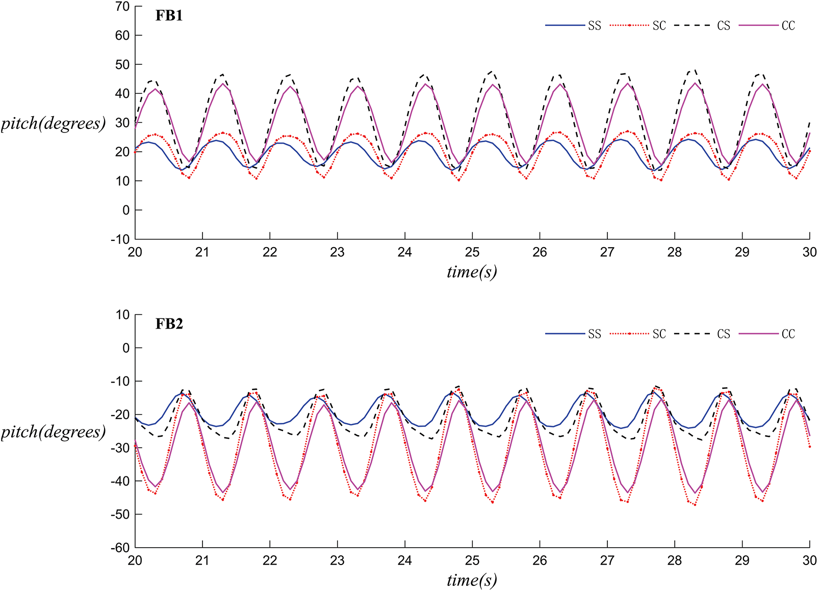
Figure 11: The motion time histories of breakwaters with different configurations under Case 1 (left: FB 1, right: FB 2): (1) heave (2) surge (3) pitch
In terms of heave motion, the upstream bodies in the SS and SC configurations exhibit the smallest heave height. In surge motion, the SC and CS configurations show a larger range of fluctuation, while the relative fluctuation between the upstream and downstream bodies of the SS configuration is the smallest. In pitch motion, there is not a significant difference in the motion trajectories of the left and right floating bodies, with the SS configuration having the smallest amplitude of rotation. Overall, under dual wave maker conditions, spherical bodies are less effective at wave attenuation and are less stable than their rectangular counterparts.
Figs. 12–14 present simulations of the velocity fields for dual-connected floating bodies with a single wave-making plate, as well as for single and double interlinked floating bodies, using the rectangular body as an example.
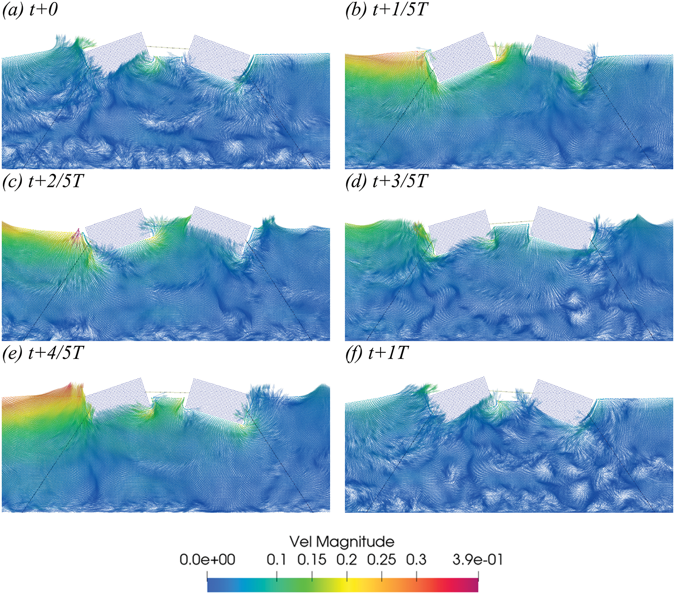
Figure 12: In Case 1´, the velocity vector diagram of the SS configuration within a one-period interval starting at t = 25 s (T = 1 s, H = 0.1 m) (a–f).
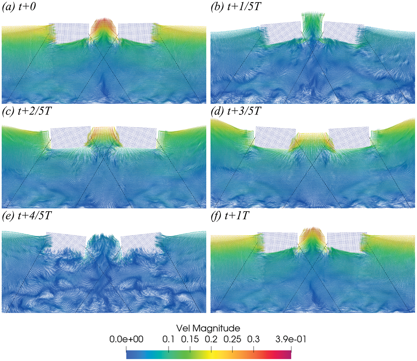
Figure 13: In Case 3, the velocity vector diagram of the SS configuration within a one-period interval starting at t = 25 s (T = 1 s, H = 0.1 m) (a–f)
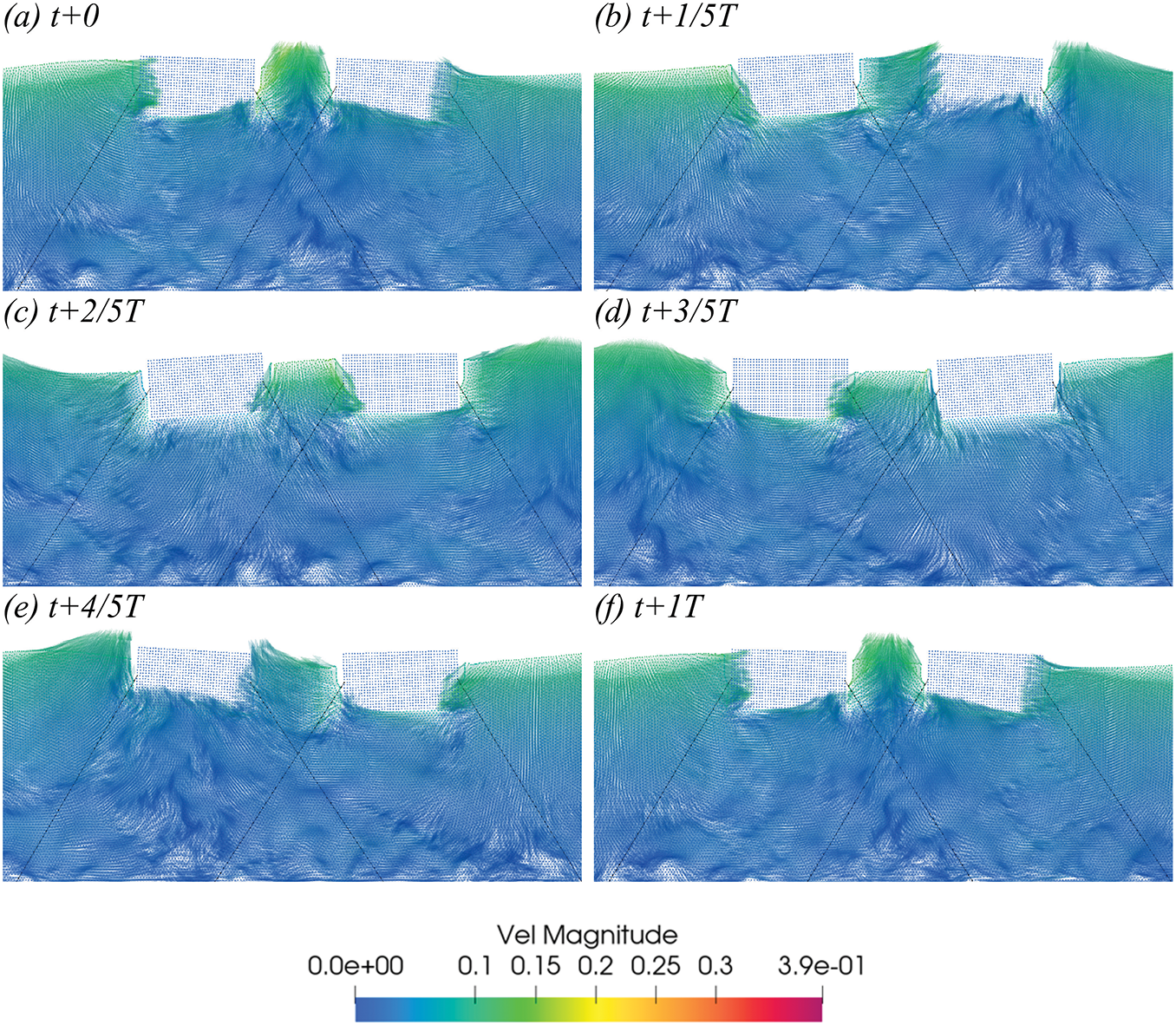
Figure 14: In Case 3´, the velocity vector diagram of the SS configuration within a one-period interval starting at t = 25 s (T = 1 s, H = 0.1 m) (a–f)
Figs. 15 and 16 illustrate the time series of the left cable tension for different configurations of the left floating body under the conditions of Case 1 and Case 3, using the rectangular body as an example. The mooring tension for all four configurations fluctuates periodically. The fluctuation range of tension is roughly between 100N and 250N. The SS tension curve is relatively stable with a smaller fluctuation amplitude. The SC and CS tension curves exhibit a larger fluctuation amplitude, showing a more pronounced periodic change. They peak at certain moments, such as 31, 33, and 35 s, similar to the SC but with slightly different curve shapes. The CC tension curve has the largest fluctuation amplitude, showing the most significant periodic change, also peaking at 31, 33, and 35 s. In terms of fluctuation amplitude, the tension fluctuation is greatest in CC, followed by CS and SC, with the smallest fluctuation in the SS. Regarding peak values, the tension peaks in CC and CS are relatively higher at certain moments, while the peak tension in SS is comparatively lower. It demonstrates the change in tension over time under four different scenarios. The tension fluctuation is greatest in CC, while the smallest in SS. Therefore, the SS configuration, which results in the lowest tension fluctuations, is less likely to cause mooring line fatigue or failure.
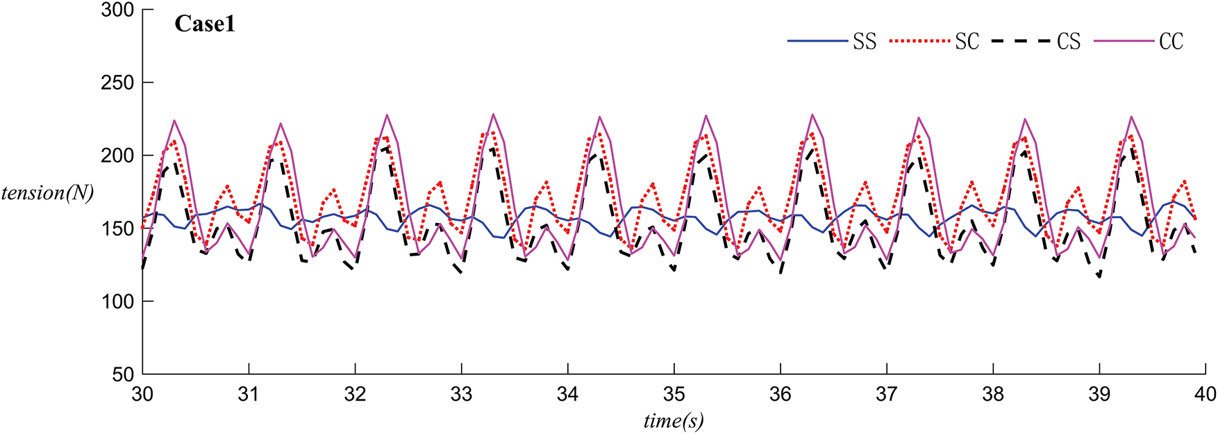
Figure 15: The time histories of the tension in the left mooring lines with different configurations connected to the floating object on the left side under Case 1
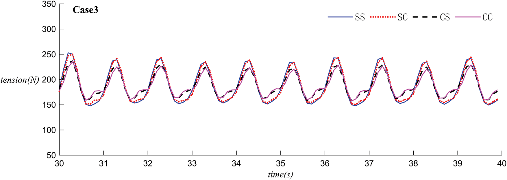
Figure 16: The time histories of the tension in the left mooring lines with different configurations connected to the separated floating object on the left side under Case 3
Figs. 17 and 18 respectively show simulations conducted on a single floating body under both single and double wave-making plate conditions, using a rectangular body as an example.
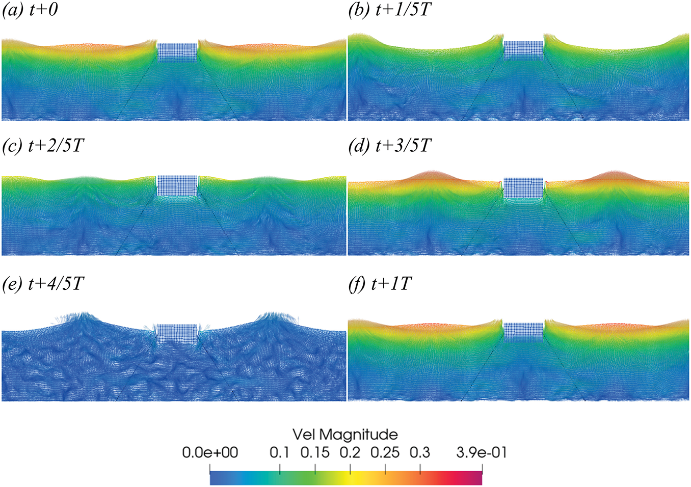
Figure 17: In Case 4, the velocity vector diagram of S within a one-period interval starting at t = 25 s (T = 1 s, H = 0.1 m) (a–f)
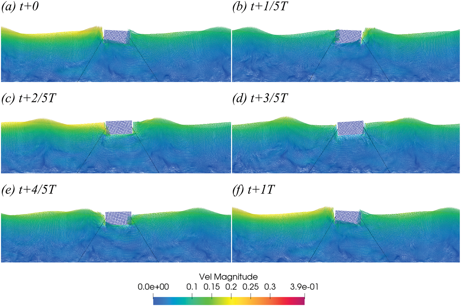
Figure 18: In Case 4´, the velocity vector diagram of S within a one-period interval starting at t = 25 s (T = 1 s, H = 0.1 m) (a–f)
Figs. 19 and 20 illustrate the velocity simulation of the central position change of a single rectangular and spherical floating body under the conditions of a single and dual wave maker. The vertical displacement Z of the floating body changes over time under different conditions. In Case 4 (dual wave maker) and Case 4´ (single wave maker), the fluctuation amplitude and period of the two curves are similar, but there are some phase differences. At most time points, the displacement in Case 4 is slightly larger than that of Case 4´. In configuration C (sphere), the results are similar, with the amplitude and period being nearly identical, but the displacement in Case 4 is again slightly larger than in Case 4´. The two figures show the change of the floating body in the vertical direction Z over time under different conditions. In the case of a single floating body, dual wave makers induce a larger vertical displacement than a single wave maker.
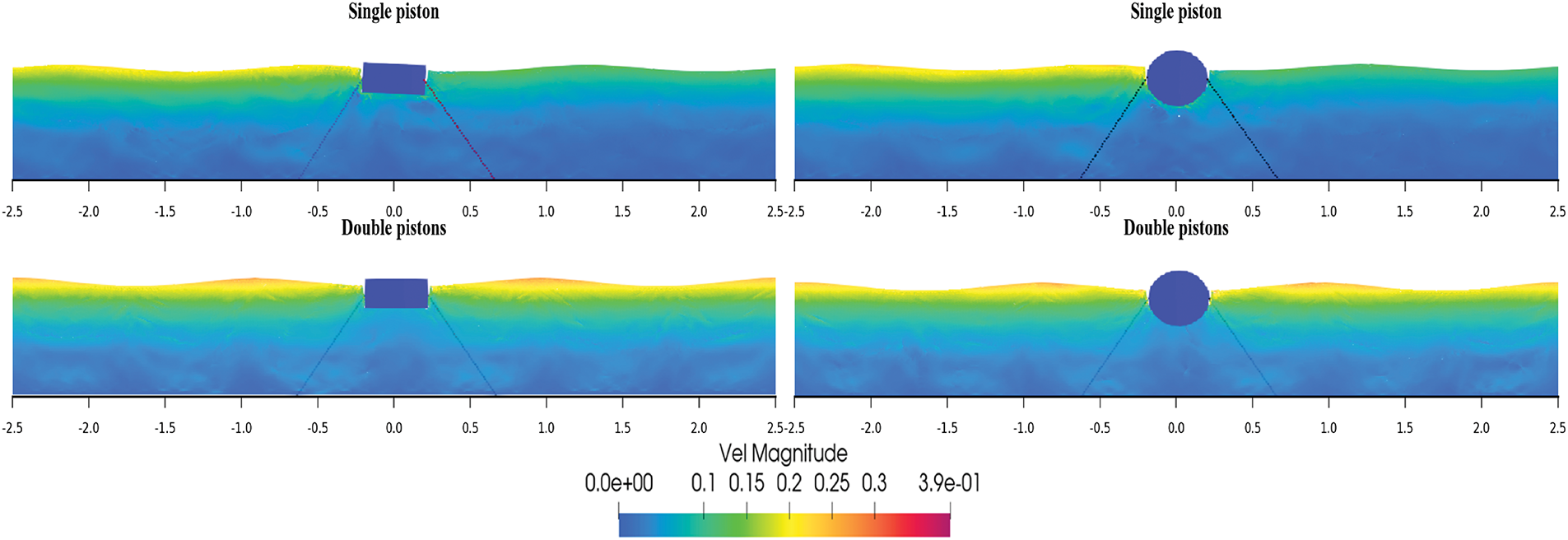
Figure 19: Velocity vector diagrams of the floating bodies in Case 4 and Case 4´
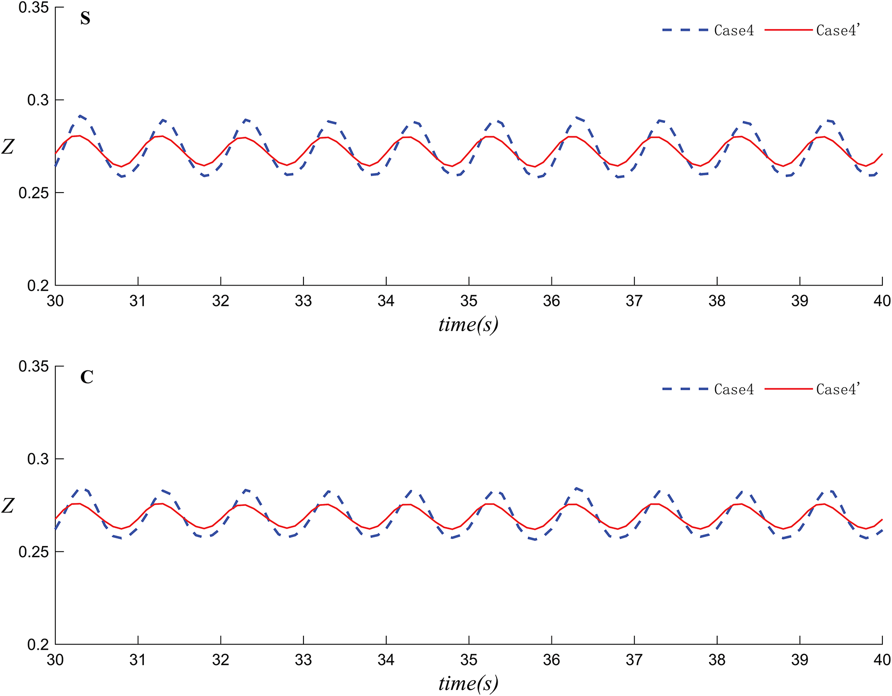
Figure 20: The variation of the center position of the floating body over time in Case 4 and Case 4´ (upper: rectangular prism, lower: sphere)
Figs. 21 and 22 depict the velocity simulation and the change in wave surface elevation over time at WG3 (x = 4 m) for Case 1, Case 3, and Case 4, where
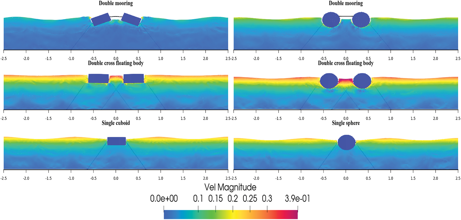
Figure 21: Velocity vector diagrams of the floating body motion in Case 1, Case 3 and Case 4
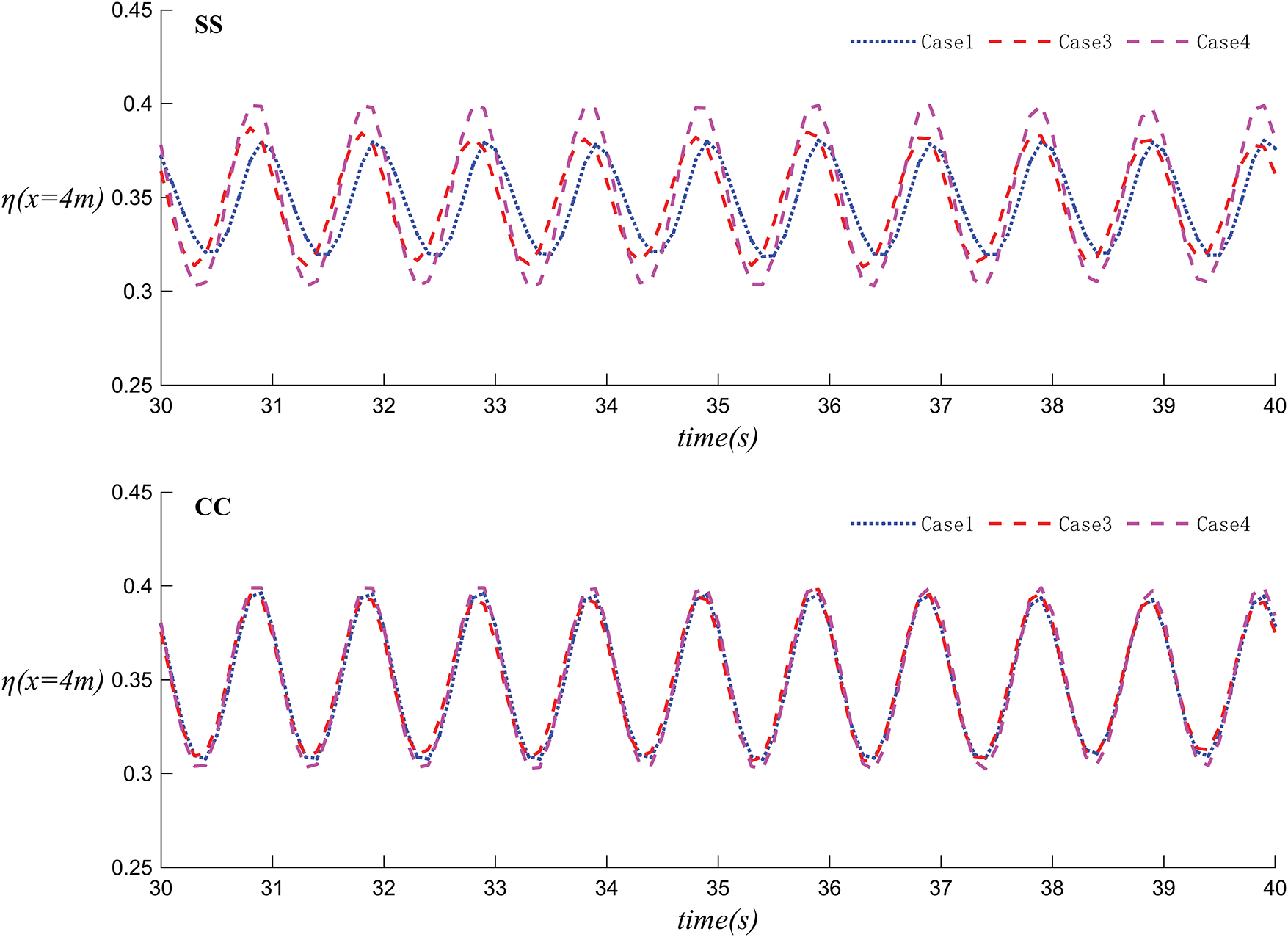
Figure 22: The variation of wave surface height over time in Case 1, Case 3 and Case 4
Figs. 23 and 24 represent the velocity simulation and the change in vertical displacement of the floating body over time for Case 1 and Case 1´. It can be observed that the floating body moves regularly with the wave period. Under dual wave maker conditions (Case 1), except for the similar vertical displacement of the left and right floating bodies in the SC configuration, the vertical displacement of the floating bodies is greater than in the single wave maker case (Case 1´). Consequently, the bodies are relatively more stable under the condition of a single wave maker. Overall, the four figures show the change in the vertical position Z of the floating bodies on the left and right sides over time in SC and CS. In the SC configuration, the displacement of the floating body in Case 1 is close to that in Case 1´, while in the CS configuration, the displacement of the floating body in Case 1 is greater than that in Case 1´.
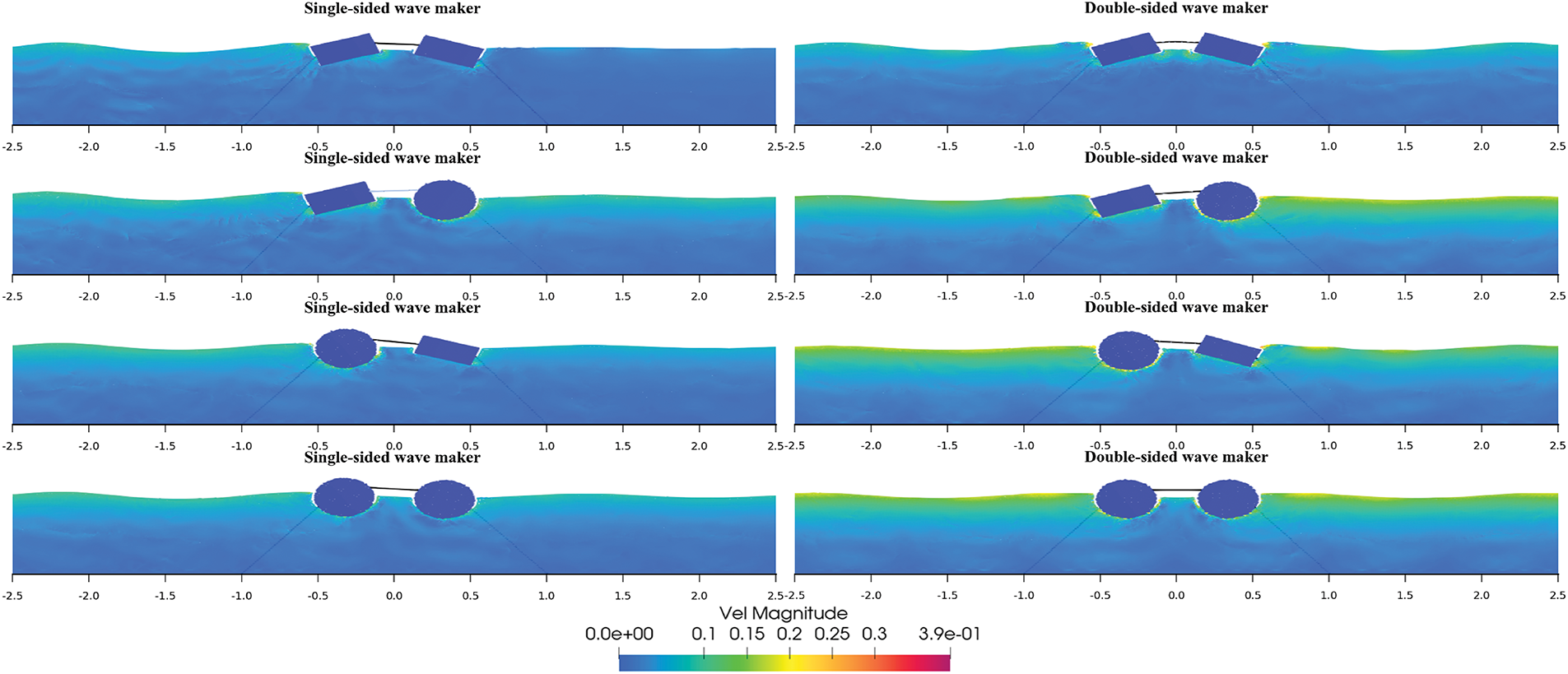
Figure 23: Velocity vector diagrams of the floating body motion in Case 1 and Case 1´
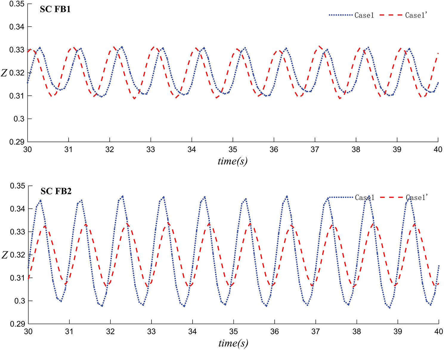
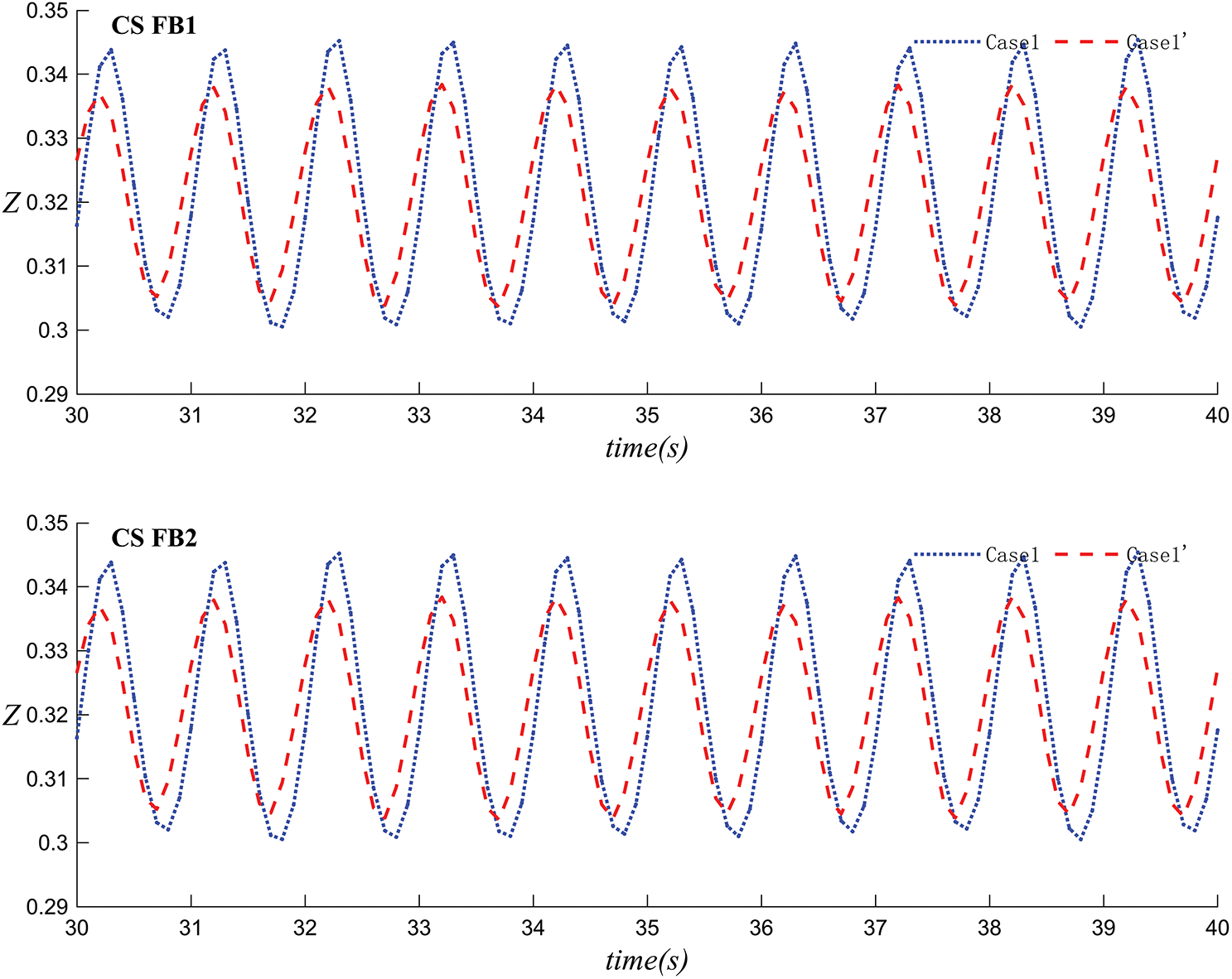
Figure 24: The variation of the center position of the floating body over time in Case 1 and Case 1´
Figs. 25 and 26 present simulations conducted on the velocities of dual floating bodies with single mooring and single or double wave-making plates, taking a rectangular body as an example.
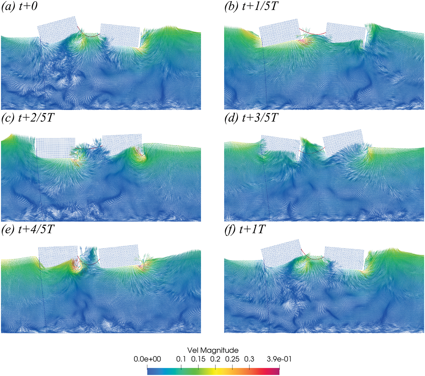
Figure 25: In Case 2, the velocity vector diagram of SS within a 25 s period (T = 1 s, H = 0.1 m) (a–f)
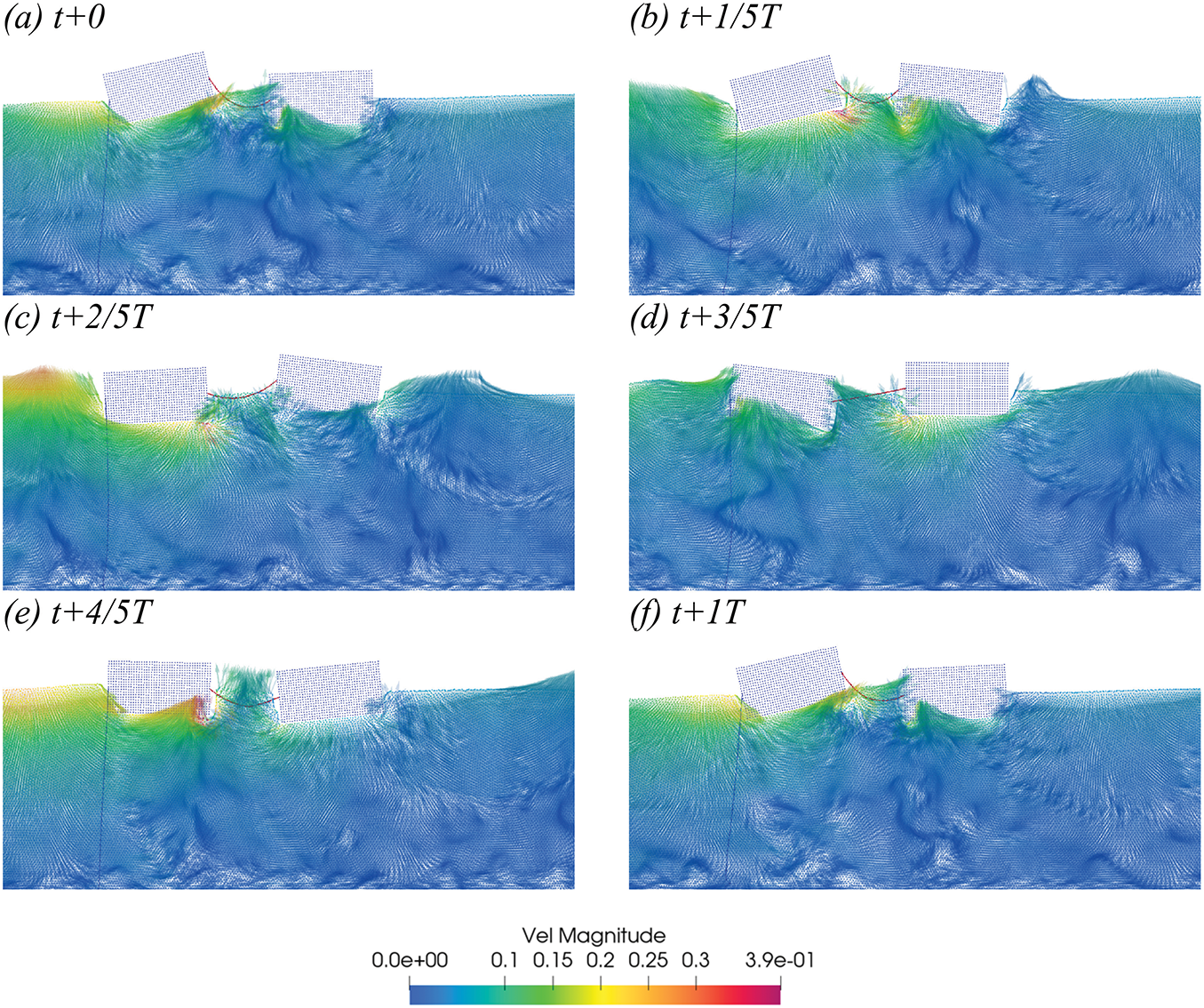
Figure 26: In Case 2´, the velocity vector diagram of SS within a 25 s period (T = 1 s, H = 0.1 m) (a–f)
Figs. 27 and 28 depict the velocity simulation and the change in wave surface elevation over time at WG3 (x = 4 m) for Case 1´, Case 2´, and Case 3´. Under the condition of a single wave maker, with the observation point 4 meters behind the floating body, the waves fluctuate regularly with the wave period. In the SS configuration, the curves for Case 1´ and Case 2´ are close for most of the time, while the curve for Case 3´ shows greater fluctuation. In SC and CS, the curve for Case 3´ exhibits the largest fluctuation, followed by Case 1´, with Case 2´ having the smallest fluctuation. In CC, the curves for Case 1´ and Case 3´ are similar, while the curve for Case 2´ is the lowest in height. Comparing the four figures, it can be concluded that for dual floating bodies under a single wave maker, the ranking of wave attenuation capability is Case 2´ > Case 1´ > Case 3´.
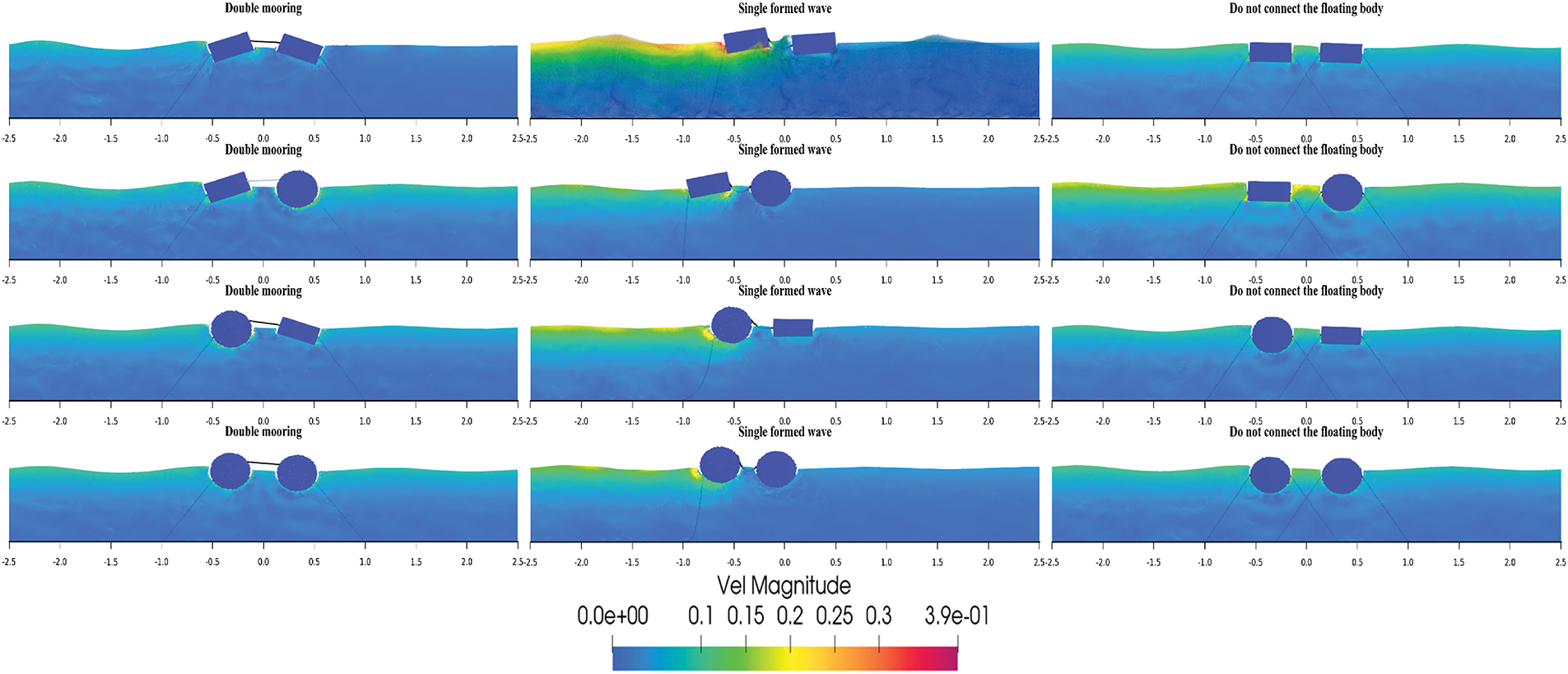
Figure 27: Velocity vector diagrams of the floating body motion in Case 1´, Case 2´ and Case 3´
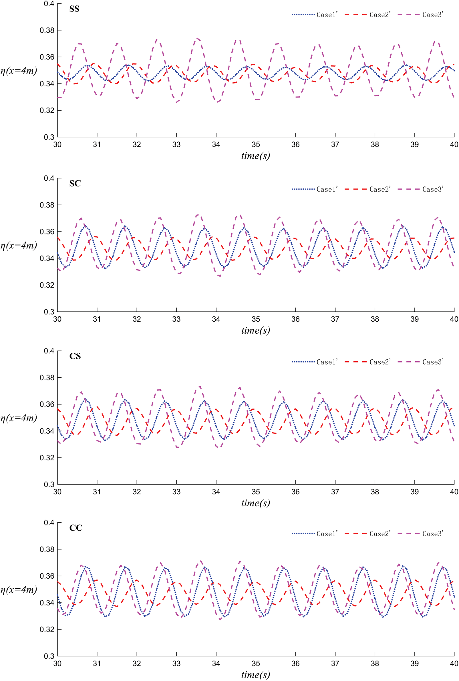
Figure 28: The variation of wave surface height over time in Case 1´ Case 2´ and Case 3´
Figs. 29 and 30 illustrate the velocity simulation and the change in wave surface elevation over time at WG3 (x = 4 m) for Case 1´, Case 3´, and Case 4´. In both the SS and CC configurations depicted in these figures, the three types of fluctuations vary periodically and regularly. In SS, Case 1´ exhibits a relatively smaller fluctuation amplitude, while the fluctuation trends of Case 3´ and Case 4´ are quite similar. In CC, the fluctuation trends of Case 1´, Case 3´, and Case 4´ are mostly consistent throughout most of the time. Comparing these two figures, under the condition of a single wave maker, the SS configuration provides superior wave dissipation compared to the CC configuration, and dual-body systems (Cases 1´ and 3´) are more effective than a single-body system (Case 4´). Moreover, the wave dissipation effect of Case 1´ is better than that of Case 3´.
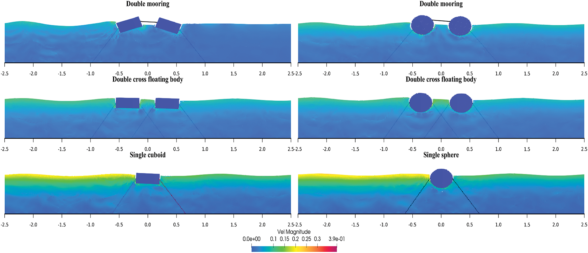
Figure 29: Velocity vector diagrams of the floating body motion in Case 1´, Case 3´ and Case 4´
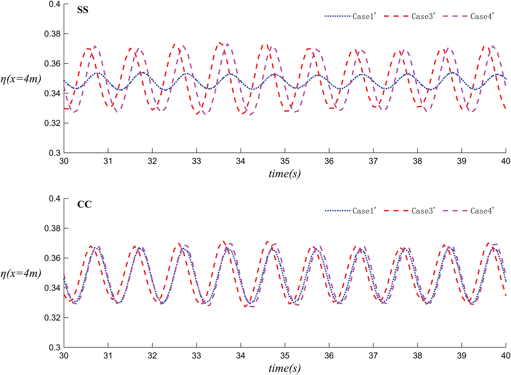
Figure 30: The variation of wave surface height over time in Case 1´ Case 3´ and Case 4´
This investigation employed an SPH-based numerical approach to analyze and compare the hydrodynamic performance of floating breakwaters featuring four different dual-body configurations. The study systematically examined the effects of wave generation methods (single and dual wave makers), mooring system configurations, and floating body geometries. Through comprehensive numerical simulations, the research provides fundamental insights into the fluid-structure interaction mechanisms that govern wave energy dissipation. The analysis leads to several important conclusions:
(1) Comparison with published experimental data confirms that the coupled SPH-mooring model accurately simulates the interaction between waves and floating breakwaters.
(2) Of the four dual-body configurations, the dual-rectangular prism (SS) provides the best wave attenuation performance. It also experiences the lowest mooring forces under the same conditions, thereby reducing the risk of mooring line failure.
(3) With dual wave makers, the number (single or dual) and shape of the floating bodies have a minimal impact on the local wave height.
(4) Under identical wave conditions, dual-body systems are relatively more stable. For a single wave maker, the dual-moored configuration (Case 1´) offers better wave dissipation than the dual-connected configuration (Case 3´).
(5) From a cost perspective, the single-mooring, dual-connected rectangular body (Case 2´) is an effective configuration for wave height reduction.
The outcomes of this study provide significant theoretical support and practical guidance for the design and optimization of floating breakwaters. First, the SS configuration, which demonstrates superior performance in wave attenuation and mooring forces, emerges as a preferred choice in engineering design. This configuration not only enhances the stability and safety of the breakwaters but also reduces maintenance costs. Second, the single-mooring, dual-connected rectangular body, which exhibits remarkable cost-effectiveness, offers valuable references for selecting economically efficient floating breakwater designs in practical engineering. It helps optimize material usage and lower construction costs while meeting wave protection requirements. Additionally, the in-depth understanding of the interaction mechanisms between waves and floating breakwaters provided by this study lays a theoretical foundation for the future integration of floating breakwaters with wave energy conversion devices, thereby facilitating the effective utilization of wave energy. Lastly, floating breakwaters play a crucial role in reducing coastal erosion caused by waves and protecting marine ecosystems. Optimizing their hydrodynamic performance will further enhance their application value in marine environmental protection.
Despite its contributions to analyzing the hydrodynamic performance of floating breakwaters, this study is limited by its reliance on 2D numerical simulations, which cannot fully capture complex 3D phenomena such as wave diffraction and short-crestedness that significantly affect breakwater performance in real marine environments. Additionally, the study only considers regular wave conditions, whereas real ocean waves are irregular with varying heights, wavelengths, and directions, leading to different hydrodynamic responses. The study also inadequately addresses the dynamic behavior of mooring systems influenced by multiple factors like ocean currents, wind, and wave interactions. Furthermore, while focusing on hydrodynamic performance, it overlooks the critical aspects of material selection and durability, which are affected by corrosion and biofouling in marine environments and can degrade the breakwaters' performance and lifespan. Lastly, the study does not examine the performance of floating breakwaters under extreme sea conditions, such as typhoons and storm surges, which pose significant challenges including higher waves, stronger currents, and higher wind speeds. Future research is needed to address these limitations.
5.4 Future Research Directions
To address the limitations of the current study and enhance its practical relevance and accuracy, future work will focus on several key areas: conducting three-dimensional numerical simulations integrated with experimental validation to investigate complex hydrodynamic phenomena such as wave diffraction, reflection, and refraction in real marine environments; studying the performance of floating breakwaters under irregular wave conditions to analyze wave attenuation, stability, and mooring system dynamics; examining the dynamic behavior of mooring systems under the combined effects of ocean currents, wind, and waves to inform their design and optimization; researching material durability and corrosion protection to extend the service life of floating breakwaters; evaluating breakwater performance under extreme sea conditions like typhoons and storm surges to ensure stability and safety; and exploring the integration of floating breakwaters with wave energy conversion devices to achieve multifunctional designs that combine wave protection with energy production.
Acknowledgement: The SPH code in this work was developed based on the open-source code DualSPHysics (https://dual.sphysics.org/), for which the authors are most grateful.
Funding Statement: All the authors were pleased to acknowledge funding from the National Natural Science Foundation of China (No. 12462028).
Author Contributions: The authors confirm their contributions to the paper as follows: study conception and design: Azhar Halik; analysis and interpretation of results & article writing: Yini Shen. All authors reviewed the results and approved the final version of the manuscript.
Availability of Data and Materials: The data used in this study can be obtained by contacting the corresponding author.
Ethics Approval: Not applicable.
Conflicts of Interest: The authors declare no conflicts of interest to report regarding the present study.
References
1. Lu W, Zhang J, Zhong H, Li X, Guo X. Impact of rogue waves on semi-submersible platforms: an experimental investigation of wave run-up and air-gap responses. Ocean Eng. 2024;313:119425. doi:10.1016/j.oceaneng.2024.119425. [Google Scholar] [CrossRef]
2. Onorato M, Residori S, Bortolozzo U, Montina A, Arecchi FT. Rogue waves and their generating mechanisms in different physical contexts. Phys Rep. 2013;528(2):47–89. doi:10.1016/j.physrep.2013.03.001. [Google Scholar] [CrossRef]
3. Pelinovsky E, Kharif C. Outcomes of the special issue on extreme and rogue waves. Nat Hazards and Earth Syst Sci. 2011;11(7):2043–6. doi:10.5194/nhess-11-2043-2011. [Google Scholar] [CrossRef]
4. Jeon W, Park S, Jeon GM, Park JC. Computational study on rogue wave and its application to a floating body. Appl Sci. 2022;12(6):2853. doi:10.3390/app12062853. [Google Scholar] [CrossRef]
5. Cui J, Chen X, Sun PN, Li MY. Numerical investigation on the hydrodynamic behavior of a floating breakwater with moon pool through a coupling SPH model. Ocean Eng. 2022;248:110849. doi:10.1016/j.oceaneng.2022.110849. [Google Scholar] [CrossRef]
6. Guo W, Zou J, He M, Mao H, Liu Y. Comparison of hydrodynamic performance of floating breakwater with taut, slack, and hybrid mooring systems: an SPH-based preliminary investigation. Ocean Eng. 2022;258:111818. doi:10.1016/j.oceaneng.2022.111818. [Google Scholar] [CrossRef]
7. Ren B, He M, Li Y, Dong P. Application of smoothed particle hydrodynamics for modeling the wave-moored floating breakwater interaction. Appl Ocean Res. 2017;67:277–90. doi:10.1016/j.apor.2017.07.011. [Google Scholar] [CrossRef]
8. Liu Z, Wang Y. Numerical studies of submerged moored box-type floating breakwaters with different shapes of cross-sections using SPH. Coast Eng. 2020;158:103687. doi:10.1016/j.coastaleng.2020.103687. [Google Scholar] [CrossRef]
9. Chen Y, Liu Y, Meringolo DD, Hu JM. Study on the hydrodynamics of a twin floating breakwater by using SPH method. Coast Eng. 2023;179:104230. doi:10.1016/j.coastaleng.2022.104230. [Google Scholar] [CrossRef]
10. Samuel SP, Gayathri R, Koley S, Muthusamy C. Motion responses with hydrodynamic factors in designing a floating breakwater and wave energy converter: a review. J Ocean Eng Mar Energy. 2025;11(1):233–63. doi:10.1007/s40722-024-00372-8. [Google Scholar] [CrossRef]
11. Xu R, Stansby P, Laurence D. Accuracy and stability in incompressible SPH (ISPH) based on the projection method and a new approach. J Comput Phys. 2009;228(18):6703–25. doi:10.1016/j.jcp.2009.05.032. [Google Scholar] [CrossRef]
12. Vacondio R, Rogers BD, Stansby PK, Mignosa P, Feldman J. Variable resolution for SPH: a dynamic particle coalescing and splitting scheme. Comput Methods Appl Mech Eng. 2013;256:132–48. doi:10.1016/j.cma.2012.12.014. [Google Scholar] [CrossRef]
13. Sun PN, Colagrossi A, Marrone S, Antuono M, Zhang AM. Multi-resolution delta-plus-SPH with tensile instability control: towards high Reynolds number flows. Comput Phys Commun. 2018;224:63–80. doi:10.1016/j.cpc.2017.11.016. [Google Scholar] [CrossRef]
14. Meringolo DD, Marrone S, Colagrossi A, Liu Y. A dynamic
15. Dang BL, Nguyen-Xuan H, Wahab MA. Numerical study on wave forces and overtopping over various seawall structures using advanced SPH-based method. Eng Struct. 2021;226:111349. doi:10.1016/j.engstruct.2020.111349. [Google Scholar] [CrossRef]
16. Rogers BD, Dalrymple RA, Stansby PK. Simulation of caisson breakwater movement using 2-D SPH. J Hydraul Res. 2010;48(sup1):135–41. doi:10.1080/00221686.2010.9641254. [Google Scholar] [CrossRef]
17. Barreiro A, Crespo AJC, Domınguez JM, Gómez-Gesteira M. Smoothed particle hydrodynamics for coastal engineering problems. Comput Struct. 2013;120:96–106. doi:10.1016/j.compstruc.2013.02.010. [Google Scholar] [CrossRef]
18. Vacondio R, Mignosa P, Pagani S. 3D SPH numerical simulation of the wave generated by the Vajont rockslide. Adv Water Resour. 2013;59:146–56. doi:10.1016/j.advwatres.2013.06.009. [Google Scholar] [CrossRef]
19. Altomare C, Crespo AJC, Rogers BD, Dominguez JM, Gironella X, Gómez-Gesteira M. Numerical modelling of armour block sea breakwater with smoothed particle hydrodynamics. Comput Struct. 2014;130:34–45. doi:10.1016/j.compstruc.2013.10.011. [Google Scholar] [CrossRef]
20. Altomare C, Tagliafierro B, Dominguez JM, Suzuki T, Viccione G. Improved relaxation zone method in SPH-based model for coastal engineering applications. Appl Ocean Res. 2018;81:15–33. doi:10.1016/j.apor.2018.09.013. [Google Scholar] [CrossRef]
21. Omidvar P, Stansby PK, Rogers BD. SPH for 3D floating bodies using variable mass particle distribution. Int J Numer Meth Fluids. 2013;72(4):427–52. doi:10.1002/fld.3749. [Google Scholar] [CrossRef]
22. Crespo AJC, Altomare C, Domınguez JM, González-Cao J, Gómez-Gesteira M. Towards simulating floating offshore oscillating water column converters with smoothed particle hydrodynamics. Coast Eng. 2017;126:11–26. doi:10.1016/j.coastaleng.2017.05.001. [Google Scholar] [CrossRef]
23. Domínguez JM, Crespo AJC, Hall M, Altomare C, Wu M, Stratigaki V, et al. SPH simulation of floating structures with moorings. Coast Eng. 2019;153:103560. doi:10.1016/j.coastaleng.2019.103560. [Google Scholar] [CrossRef]
24. Dalrymple RA, Rogers BD. Numerical modeling of water waves with the SPH method. Coast Eng. 2006;53(2):141–7. doi:10.1016/j.coastaleng.2005.10.004. [Google Scholar] [CrossRef]
25. Peng W, Lee KH, Shin SH, Mizutani N. Numerical simulation of interactions between water waves and inclined-moored submerged floating breakwaters. Coast Eng. 2013;82:76–87. doi:10.1016/j.coastaleng.2013.07.002. [Google Scholar] [CrossRef]
26. Hu X, Halik A. Numerical simulation of freak wave generation and evolution process based on SPH method. J Phys Conf Series. 2024;2756(1):012057. doi:10.1088/1742-6596/2756/1/012057. [Google Scholar] [CrossRef]
27. Zhang H, Sun B, Li Z, Wang F. Wave attenuation and motion response of floating breakwater with sponge material. Ocean Eng. 2023;277:114325. doi:10.1016/j.oceaneng.2023.114325. [Google Scholar] [CrossRef]
28. Liang JM, Liu Y, Chen YK, Li AJ. Experimental study on hydrodynamic characteristics of the box-type floating breakwater with different mooring configurations. Ocean Eng. 2022;254:111296. doi:10.1016/j.oceaneng.2022.111296. [Google Scholar] [CrossRef]
29. Wendland H. Piecewise polynomial, positive definite and compactly supported radial functions of minimal degree. Adv Comput Math. 1995;4:389–96. doi:10.1007/bf02123482. [Google Scholar] [CrossRef]
30. Hall M, Goupee A. Validation of a lumped-mass mooring line model with DeepCwind semisubmersible model test data. Ocean Eng. 2015;104:590–603. doi:10.1016/j.oceaneng.2015.05.035. [Google Scholar] [CrossRef]
31. Crespo AJC, Domínguez JM, Rogers BD, Gómez-Gesteira M, Longshaw S, Canelas R, et al. DualSPHysics: open-source parallel CFD solver based on Smoothed Particle Hydrodynamics (SPH). Comput Phys Commun. 2015;187:204–16. [Google Scholar]
32. Liu Z, Wang Y, Hua X. Numerical studies and proposal of design equations on cylindrical oscillating wave surge converters under regular waves using SPH. Energy Convers Manage. 2020;203:112242. doi:10.1016/j.enconman.2019.112242. [Google Scholar] [CrossRef]
33. Antuono M, Colagrossi A, Marrone S, Molteni D. Free-surface flows solved by means of SPH schemes with numerical diffusive terms. Comput Phys Commun. 2010;181(3):532–49. doi:10.1016/j.cpc.2009.11.002. [Google Scholar] [CrossRef]
Cite This Article
 Copyright © 2025 The Author(s). Published by Tech Science Press.
This work is licensed under a Creative Commons Attribution 4.0 International License , which permits unrestricted use, distribution, and reproduction in any medium, provided the original work is properly cited.
 Downloads
 Citation Tools