
 Submit a Paper
 Propose a Special lssue
 Open Access
ARTICLE

Porous Media-Based Full-Scale Modeling of Thermal Behavior in Rotary Gas-Gas Heat Exchangers
1 School of Energy and Environment, Anhui University of Technology, Ma’anshan, 243002, China
2 School of Materials Science and Engineering, Anhui University of Technology, Ma’anshan, 243002, China
* Corresponding Author: Fuping Qian. Email:
Fluid Dynamics & Materials Processing 2025, 21(8), 1895-1915. https://doi.org/10.32604/fdmp.2025.067899
Received 15 May 2025; Accepted 15 July 2025; Issue published 12 September 2025
 View Full Text
 Download PDF
Abstract
The rotary gas-gas heat exchanger (GGH) is a vital component in waste heat recovery systems, particularly for Selective Catalytic Reduction (SCR) processes employed in cement kiln operations. This study investigates the thermal performance of a rotary GGH in medium- and low-temperature denitrification systems, using a simplified porous medium model based on its actual internal structure. A porous medium representation is developed from the structural characteristics of the most efficient heat transfer element, and a local thermal non-equilibrium (LTNE) model is employed to capture the distinct thermal behaviors of the solid matrix and gas phase. To account for the rotational dynamics of the system, the multiple reference frame (MRF) approach is adopted. Numerical simulation results exhibit an average error of less than 5%, demonstrating the model’s reliability and predictive accuracy. The temperature distributions of both the metallic heat exchange surfaces and the flue gas are systematically analyzed. Results indicate that the solid and gas phases exhibit significant non-equilibrium thermal behavior. Notably, the circumferential temperature fluctuations of both the heat exchange surfaces and flue gas vary markedly with changes in rotational speed. At low rotational speeds, the temperature non-uniformity coefficient reaches 4.296, while at high speeds it decreases to 0.4813—indicating that lower speeds lead to more pronounced temperature fluctuations. The simulated temperature field patterns are consistent with experimental observations, validating the effectiveness of the modeling approach.Keywords
The cement, thermal power, and steel industries constitute pivotal pillars of the world industrial economy [1]. However, these sectors exhibit substantial production capacities and inevitably generate significant emissions. Consequently, recovering and reutilizing waste heat from industrial exhaust gases holds considerable practical significance for enhancing enterprise profitability and mitigating energy wastage. Functioning as an efficient thermal recovery device, the rotary heat exchanger utilizes densely arranged heat transfer plates within its rotor to facilitate heat exchange. Upon exposure to high-temperature flue gas, the heat exchange elements absorb thermal energy, while rotation into low-temperature flue gas regions enables release of stored thermal energy to preheat the gas stream. This cyclical process enables continuous heat recovery between high- and low-temperature gas streams [2]. Owing to its little volume, high thermal efficiency, and cost-effectiveness, rotary heat exchangers have been widely implemented in industrial applications including desulfurization, denitrification, and coal-fired power generation [3,4]. The flow dynamics and heat transfer characteristics of the exchange elements fundamentally govern the resistance performance and thermal efficiency of these systems, as dictated by their structural configuration.
Owing to superior applicability and thermal performance characteristics, rotary heat exchangers exhibit broad application potential. Consequently, extensive research efforts have been devoted to these systems in recent decades. Numerical methods have been widely employed to model flow and heat transfer phenomena within rotary heat exchangers [5,6]. Padhi and Ghose [7] simulated the rotary air preheater by applying the porous media method. The effects of rotor speed, inlet mass flow, matrix material and hot fluid inlet temperature on the performance of rotary air preheaters were studied. Bu et al. [8] used the porous medium method and local non-equilibrium thermal model to accurately obtain the temperature distribution of the matrix and gas. By comparing the simulation results with the experimental data, a good agreement is obtained. Hajebzadeh et al. [9] used the thermal non-equilibrium porous media model to conduct three-dimensional CFD simulation of Ljungstrom, so as to extend the service life of the rotary regenerative air preheater (Ljungstrom) in Bandar Abbas power plant. Yang et al. [10] semi-analyzed and studied the forced convection heat transfer characteristics in a plate heat exchanger filled with porous media through a local thermal nonequilibrium model. Shang et al. [11] developed the numerical model of a porous media heat exchanger. The local thermal nonequilibrium heat transfer model captures the heat transfer between solid and fluid components. Dallaire et al. [12] used the finite volume formula to carry out numerical calculations on the rotary GGH, modeled the heat exchanger as a porous medium and solved it by using the thermal equilibrium and non-thermal equilibrium models, respectively. The influence of the relative period of heating and cooling flow on the rotating GGH is considered, and the relationship between the period of cooling and heating flow and the dimensionless pressure drop is given. Alhusseny and Turan [13] used porous media to simplify and simulate the flow and heat transfer process in rotary GGH, and obtained the permeability and inertia coefficient of porous media through the geometric properties of heat exchange elements according to the empirical equation, compared the overall system performance of rotary GGH corresponding to heat exchange elements with different structural characteristics, and found that increasing the filling density of heat exchange elements can improve the efficiency of heat exchanger. Chen et al. [14] provided a herringbone contact flexible seal (HCFS) to reduce leakage in a rotating air preheater (RAPH). The friction force of HCFS was calculated using finite element method (FEM) and compared with experimental data, demonstrating that HCFS technology is beneficial for reducing leakage, improving heat transfer efficiency, and optimizing RAPH. Sphaier and Worek [15] established a new mathematical model of adsorption rotary heat and mass exchanger to describe the transport phenomenon in the porous region in detail. Through the in-depth discussion of the related dimensionless groups, a completely normalized governing partial differential equation system is obtained. Li et al. [16] studied the thermal deformation modes of rotors under different conditions, explored their effects on air leakage, and conducted a comprehensive analysis of air leakage fluctuations in different pipelines. Drobnič et al. [17] studied the temperature distribution generated by the flue gas flow, regeneration heat transfer, and preheater matrix through air preheaters and adjacent channels. Especially the impact of leaks on the flue gas parameters of preheaters. Numerical analysis and experimental results indicate that smoke parameters have a significant dependence on various sealing settings. Zhang et al. [18] established an energy balance equation for the heat transfer process in an air preheater by discretizing it into multiple heat transfer units, taking into account the unstable heat transfer caused by rotor rotation. Bu et al. [19] can avoid blockages and corrosion in the two preheaters by implementing an appropriate split design and continuously adjusting the recirculation flow rate. Using the numerical finite difference method to model the preheater and calculate the temperature distribution.
Current research on rotary heat exchangers and their heat exchange elements predominantly focuses on coal-fired power plant applications, while studies on rotary GGH in cement kiln flue gas purification waste heat recovery systems remain limited. Although investigations of denitrification-system rotary heat exchangers exist, critical shortcomings persist—notably inadequate integration between heat exchange and overall system architecture, along with oversimplified single-objective optimization frameworks. This study employs the low-temperature denitrification system of cement kilns as its research background. The rotary GGH rotor compartment incorporates densely packed heat exchange elements, rendering comprehensive modeling and simulation of individual components computationally prohibitive. Parallel arrangement of these elements partitions the rotor into multiple structurally uniform microchannels, exhibiting morphological characteristics consistent with porous media models as established in the literature [12,20,21]. The core heat transfer region of rotary GGH may be simplified as a porous medium. A mathematical model derived from this simplification was employed to compute heat and mass transfer phenomena within the rotary heat exchanger. Computational results demonstrate strong concordance with experimental data, validating the porous medium model’s predictive accuracy [15]. A heat exchange element model corresponding to the size of the studied rotary GGH was established, and the basic parameters such as the resistance coefficient of the porous medium were obtained. According to the above premise, a porous medium approximation was applied to simplify the GGH geometry and the rotary process of the rotor was realized through the selection of the rotary model. The assumption and simplification of the model can not only ensure the display of the rotary GGH rotary heat transfer process, but also greatly reduce computational resources.
2.1 Basic Parameters of Porous Media
When simulating the flow in porous media, the homogenization macro method can effectively simplify the geometric complexity of real porous materials. Porosity is a basic parameter of porous media, which refers to the volume proportion of fluid in the material (i.e., the open volume fraction of the medium). Porosity reflects the arrangement of materials in the region and determines the apparent velocity in the porous media region. Therefore, it affects the flow and transmission of working fluids in the porous media. The microscopic flow through the pore space in the homogeneous region is uniformly distributed on the macro scale. The following methods are commonly used to calculate the porosity of solid skeletons.
Volume porosity:
where, UV is the volume of pores in porous media, m3; Ur is the total volume of porous area, m3.
Surface porosity:
where,
Line porosity:
where,
Since the heat exchange elements in the rotary GGH are arranged in parallel in the rotor perpendicular to the end face of the flue gas inlet, it is considered that the pore size does not change along the flow direction of the working medium, and the surface porosity can be selected to calculate the porosity of the rotary GGH.
2.1.2 Resistance Equation of Porous Media
The porous medium model, as a widely used computational fluid dynamics resistance medium model, simulates the resistance experienced by the fluid in the porous region by adding a momentum source term to the standard flow equation. The momentum source term acts on the fluid to generate a pressure gradient, transforming the porous region into a fluid region with an increased resistance source term. Its core is to equate the complex porous structure at the microscale with a continuous medium at the macroscale.
where,
In the rectangular coordinate system, the momentum source term can be expressed as follows, in which the first term is the viscous loss term and the second term is the inertial loss term.
where, ρ is the density of the fluid, kg/m3;
In the cylindrical coordinate system, matrices D and C can be simplified to obtain the following form.
In the formula,
To obtain the pressure drop of a porous medium with a length of in the flow direction, the formula for calculating the resistance coefficient of the porous medium is:
Based on the heat exchange element structure with the best performance determined by the previous analysis [22], the Nusselt number was used as the comprehensive evaluation of heat exchange effect, and the values of interphase heat transfer coefficient (h) and thermal conductivity coefficient (α) were determined by comparing and selecting the Nusselt number corresponding to the most appropriate working condition. Therefore, this heat exchange element was selected for application in rotary GGH. According to references [23], the geometric properties of heat exchange elements can be transformed into porous medium parameters for simulation based on empirical equations. The momentum equation is solved by setting the velocity inlet boundary condition for the heat exchange element, with no slip condition on the channel wall. The pressure drop values corresponding to different inlet velocities are calculated, and the pressure velocity relationship is fitted into a second-order polynomial in the form of the following empirical formula.
The variation of resistance in the heat exchange element channel with velocity is shown in Fig. 1. By comparing Formulas (7) and (8), the coefficients of the viscous resistance and inertial resistance terms in the porous region of the rotary GGH can be obtained.
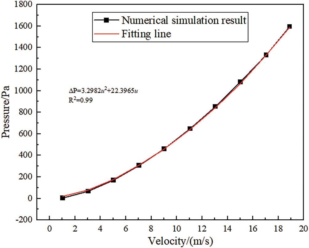
Figure 1: Relationship between pressure drop and velocity variation
2.2 Porous Medium Heat Transfer Model
Convective heat transfer in porous media constitutes a complex conjugate thermal transport process. Based on thermal phenomena between solid and fluid phases, it is categorized into Local Thermal Equilibrium (LTE) and Local Thermal Non-Equilibrium (LTNE) models [10], both studied through volume-averaging methodologies. The LTE model represents a special case of the LTNE framework wherein solid matrix and fluid temperatures are assumed asymptotically equivalent, leading to the following simplified energy equation:
Employing the LTE model within its valid regime reduces computational expense. However, its applicability is constrained by dimensionless criteria: the Biot number (Bi), Rayleigh number (Ra), Darcy number (Da), and solid-to-fluid thermal conductivity ratio. This model remains admissible only under sufficiently low working fluid velocities where interphase temperature differentials become negligible.
In porous media, when the initial temperature difference between solids and fluids is large or the fluid flow rate is fast, and the solid-liquid thermal conductivity ratio increases, the heat transfer rate between fluids and solids decreases, and the temperature non-uniformity of solids increases. The error of using the LTE model is too large, and in this case, the LTNE model needs to be adopted. Heat and mass coupling transfer in porous media, where both fluids and solids have energy conservation equations. The LTNE model of porous media considers the temperature difference between the fluid and solid in porous media, and couples two different energy equations between the fluid and solid phases, thus achieving higher accuracy in displaying the thermal characteristics of the system. ANSYS FLUENT uses the double element method to solve the LTNE model, while simultaneously solving for both solid and fluid regions through heat transfer coupling. The dual energy equation for the local LTNE model in porous media is as follows [24].
Fluid energy equation:
Solid energy equation:
In the formula, γ is the porosity of the porous medium region; kf,eff, ks,eff are the effective thermal conductivity coefficients of fluids and solids, respectively, W/(m/s); α is the specific surface area of the porous medium region, m2/m3; uf is the flow velocity of the fluid; hsf is the heat transfer coefficient between fluid and solid; Tf and Ts are the temperatures of the fluid and solid, K; cpf and cs are the specific heat capacities of the fluid and solid, respectively, J/(kg·K); ρf and ρs are the densities of fluid and solid, respectively, kg/m3.
Accordingly, considering the heat transfer characteristics of rotary GGH, the LTNE model is more reasonable to be employed to develop the heat transfer between the solid and the fluid instead of the LTE model.
The dynamic mesh model uses the Fluent solver to move boundaries or targets, which can solve the problem of the boundary of the computational domain moving over time. When using it, the initial mesh and motion description of the dynamic region need to be provided. The dynamic grid model transfers data through grid deformation and uses conservation equations for calculation. The calculation result of the current time step determines the motion situation of the next time step, that is, the grid volume Vn+1 = Vn + dV/dtΔt of the (n + 1)-th step. The update of the volume grid at each time step is automatically completed by Fluent based on the new position of the boundary conditions. In the dynamic mesh model, mesh quality has a significant impact on mesh updates. During computation, the mesh constantly deforms and needs to be rechecked, resulting in a decrease in computation speed as the number of steps increases. The conservation equation for the dynamic mesh of boundary motion is as follows [25]:
In the equation,
Employing backward time differencing, the preceding equation may be reformulated as:
In the formula, n and n + 1 respectively represent the current and next time steps.
When modeling the sliding mesh model, it is necessary to establish the moving region and the static region, respectively, and the interchange interface between each region and the adjacent region is needed to realize the information transmission through the sliding mesh contact surface overlapped between different regions, but there is no need to overlap between different regions or mesh nodes to correspond one by one. The sliding grid is also calculated by using the conservation equation. In the calculation, one domain slides along the grid boundary relative to the other domain. Within the time step, the grid in the moving region obtains new coordinates and researches the corresponding relationship of grid elements at the contact surface. The information exchange between different domains is realized at the contact surface by using the spatial flux conservation interpolation algorithm. The sliding grid model assumes that the flow is unsteady, and it has high accuracy in calculating the motion problem of multi reference system, but it is also the most demanding for calculation. It is usually adopted when it is necessary to obtain the accurate solution of the interaction time between the rotor and the stator. There is no motion reference system attached to the computational domain in the sliding mesh model, and the mesh is rigid. The mesh volume Vn+1 = Vn in step n + 1, so dV/dt = 0, is substituted into Eq. (12), and the conservation equation can be simplified as follows [26].
2.3.3 The Multireference Frame (MRF) Model
Multiple Reference Frame Model (MRF) assumes that the flow is constant and the computational grid is fixed, which will not cause relative motion between two adjacent computational domains. By establishing different reference frames in different domains or subdomains of the entire computational domain, each domain has independent motion modes. The flow field information for solving the control equations in the domain is converted into absolute velocity at the interface for exchange. The MRF model does not rotate the region but rather the coordinate system, causing relative motion in the originally stationary region. Its coordinates are converted into a rotating coordinate system that rotates relative to the inertial coordinate system. The position vector of a point in the rotation calculation domain is denoted as r, and the velocity in the rotation domain can be calculated as shown in Eq. (15). The MRF model is suitable for most time averaged flow calculations. When the relative motion of each point on the boundary of the grid area is basically the same, the simulation accuracy is high and the calculation is the most convenient.
In the equation, v represents the absolute velocity in the inertial coordinate system; vr represents the relative velocity in a rotating coordinate system; vt represents the translation speed of the rotation area; ω is the rotational speed.
Based on the operating characteristics of the rotary GGH, the MRF model is selected to simulate the rotation process of the rotary GGH. The smoke flow area adopts a fixed coordinate system, and the solid matrix area adopts a rotating coordinate system. The governing equation is as follows [27].
The momentum equation is:
The energy equation is:
In the formula,
Based on the comparison of the characteristics of different rotation models and combined with the content of this study, we choose the MRF model.
In this study, a numerical model is proposed to simplify the central heat transfer area of the rotary heat exchanger into porous media. The MRF model is used to simulate the rotation process of the rotary GGH, and the LTNE model is used to simulate the heat transfer behavior. Because the flow of porous media in this study is incompressible and uniform along the cross-sectional area, the coupled Darcy equation is used to simulate the fluid flow process [24].
3 Simplified Simulation Conditions and Model Validation for Rotary GGH
3.1 Simplify Simulation Conditions
To verify the feasibility of simulating rotary GGH using porous media non thermal equilibrium and multiple reference frame models, a geometric model of rotary GGH was established based on the low-temperature denitrification system in cement kilns. The model includes the inlet and outlet flues of the flue gas on both sides of the rotary GGH, the central rotor, and the sealed area between the two flues. The original flue gas and clean flue gas flow through the rotor area in a counter current direction. According to the geometric parameters shown in Table 1, the geometric model is obtained as shown in Fig. 2.
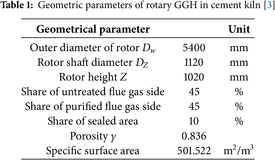
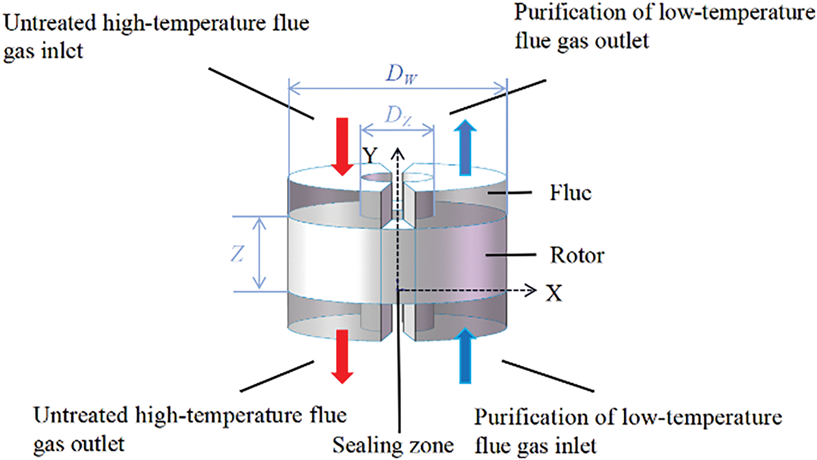
Figure 2: Schematic diagram of rotary GGH calculation model
Due to the characteristics of internal flow and heat transfer in rotary GGH, the following simulation conditions can be simplified.
(1) The velocity and temperature of the flue gas at the inlet of the rotary GGH are uniformly distributed;
(2) The physical parameters of the smoke on both sides only vary with temperature;
(3) The rotary GGH operates at a constant speed and cycle, and the operation process can be regarded as a steady state;
(4) The temperature changes more significantly in the axial and circumferential directions, while the radial changes are relatively small;
(5) The outer wall of the rotary GGH rotor and the outer wall of the rotor shaft are insulated, without external heat dissipation. Due to the low temperature of the flue gas, radiation heat transfer is not considered;
(6) Due to the fact that the time it takes for the rotor to rotate through the sealing zone is only one tenth of the rotation period, the axial heat conduction of the heat exchange element in the sealing zone can be ignored, and the temperature of the metal heating surface hardly changes in the sealing zone;
(7) The air leakage of the rotary GGH only exists in the sealed air leakage, which is located at the inlet and outlet.
3.2 Physical Property Parameters and Boundary Condition Settings
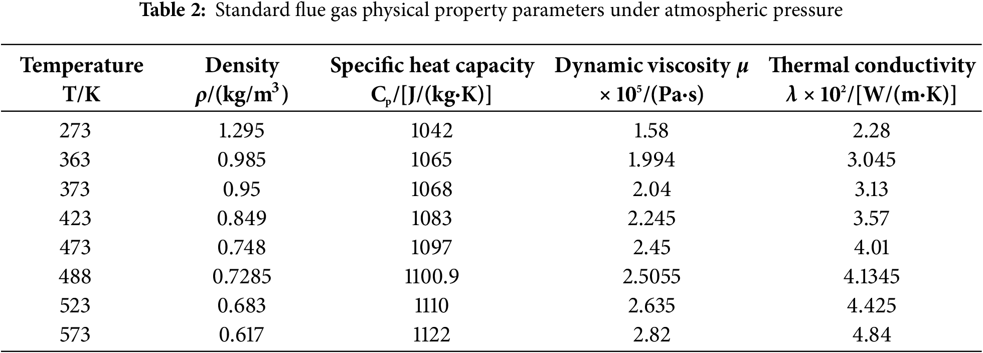
According to the process flow of the medium and low temperature denitrification system, the flue gas undergoes desulfurization and dust removal treatment before entering the rotary GGH. It can be considered that the flue gas no longer contains sulfides and dust, and the nitrogen oxide content in the flue gas is relatively low. Therefore, the flue gas is regarded as an ideal flue gas, and its physical properties change with temperature. The physical property parameters are shown in Table 2. Low carbon steel has the characteristics of high plasticity and toughness, easy processing, and low cost. It is widely used in the heat exchange components of rotary heat exchangers. Therefore, low carbon steel is selected as the material for the rotary GGH metal heat exchange surface. Using velocity inlet boundary conditions and pressure outlet boundary conditions, the flue, rotor outer wall, rotor shaft wall, and sealing chamber wall of the rotary GGH are all set as adiabatic surfaces, and the standard wall function method is used to treat the walls. Adopting the SIMPLE algorithm with pressure velocity coupling, the second-order upwind scheme discretizes the control equation. The residual value below 10−5 for the continuity equation is used as the convergence criteria [3,8].
The energy equation of the LTNE model is shown in Eqs. (9)–(11), the control equation of the MRF model is shown in Eq. (16), the momentum equation is shown in Eq. (17), and the energy equation is shown in Eq. (18).
Structured grids have six adjacent elements in the main directions at all internal points except for the boundary grids. They have the characteristics of fast grid generation and good grid quality, but are difficult to apply to models with complex geometric structures. The fitting of structured grids to surfaces and spaces is mostly achieved through parameterization or spline interpolation, which makes it easier to fit the boundaries of the region. Therefore, a smooth regional grid can be closer to the actual model, while also facilitating the preparation of data and related parameters, making it easier to assign values, resulting in good computational stability and fast convergence speed. Due to the relatively regular geometry of the rotary GGH, a structured grid is adopted to partition the model of the rotary GGH.
For CFD numerical simulation, due to the flow characteristics reflected in the grid data, different grid densities may lead to deviations in the results. If the grid size is too large and the area division is rough, the flow details will be ignored. However, if the grid density is too high, it will increase the computational cost and errors caused by numerical dissipation. Therefore, it is necessary to screen the grid accuracy of the calculation model. The results of grid sensitivity verification are as follows (Fig. 3).
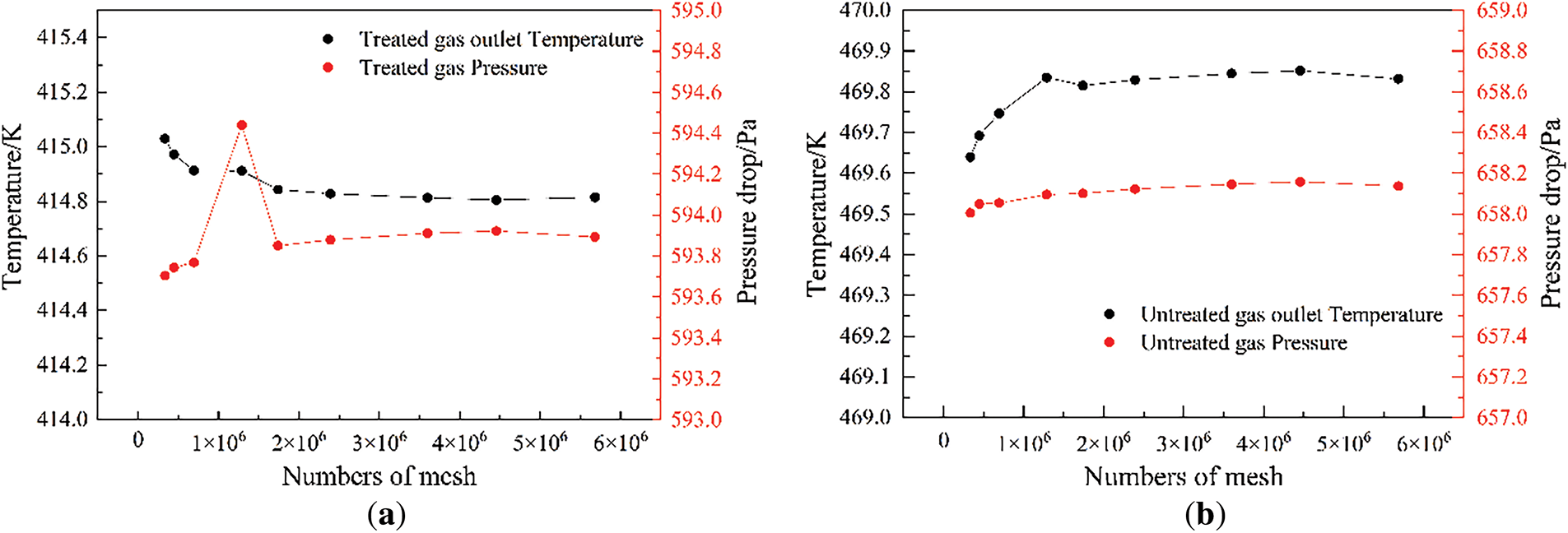
Figure 3: Grid independence verification (a) Clean flue gas side; (b) Untreated flue gas side
According to the grid sensitivity verification results, the calculation results fluctuate with the change of grid accuracy when the number of grids is below 2 million. When the number of grids reaches 2,391,940 (Fig. 4), the inlet and outlet pressure drops and outlet temperatures of the original flue gas side and the clean flue gas side tend to stabilize and no longer change significantly. Therefore, using this grid density for grid division can ensure accuracy and save computational costs.
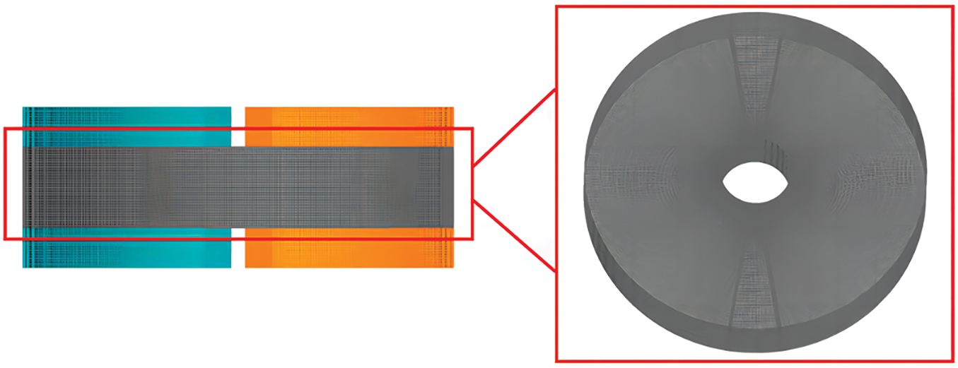
Figure 4: Schematic diagram of grid structure
The resulting computational grid model is shown in Fig. 4.
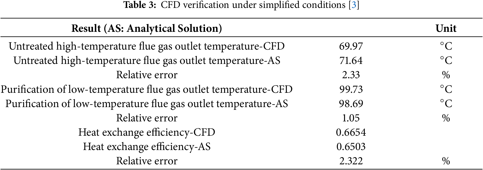
Substitute the above operating conditions and porous medium parameters for simulation. The comparison error between the simulated calculation results and the analytical solutions provided in the literature is less than 5%, as shown in Table 3, which is within an acceptable range. Prove that further simulation analysis of rotary GGH can be carried out using a porous medium non thermal equilibrium model and a multiple reference frame model.
The quantitative validation demonstrates strong concordance between numerical simulations and published reference data. In order to further explore the heat transfer law of rotary GGH, the temperature field of rotary GGH was examined through multiple analytical perspectives. Fig. 5 illustrates the flue gas temperature distribution within the GGH rotor. The high-temperature untreated flue gas and the low-temperature purified flue gas flow in reverse through the two side flues, and the inlet velocity and temperature of the flue gas are uniformly distributed. Therefore, the flue gas temperature is basically invariant radially. The temperature of the smoke along the flow direction is approximately linearly distributed, uniformly decreasing or increasing. In the sealed area, due to the lack of external smoke circulation, the gas temperature suddenly changes. Observe the temperature distribution of gas at different rotational speeds. When the rotational speed is low, the overall temperature of high-temperature untreated flue gas is high, and the temperature changes greatly at different rotational angles; As the rotational speed increases, the temperature distribution of the gas volume inside the rotor along the direction of rotation becomes more uniform, and heat transfer becomes more complete.
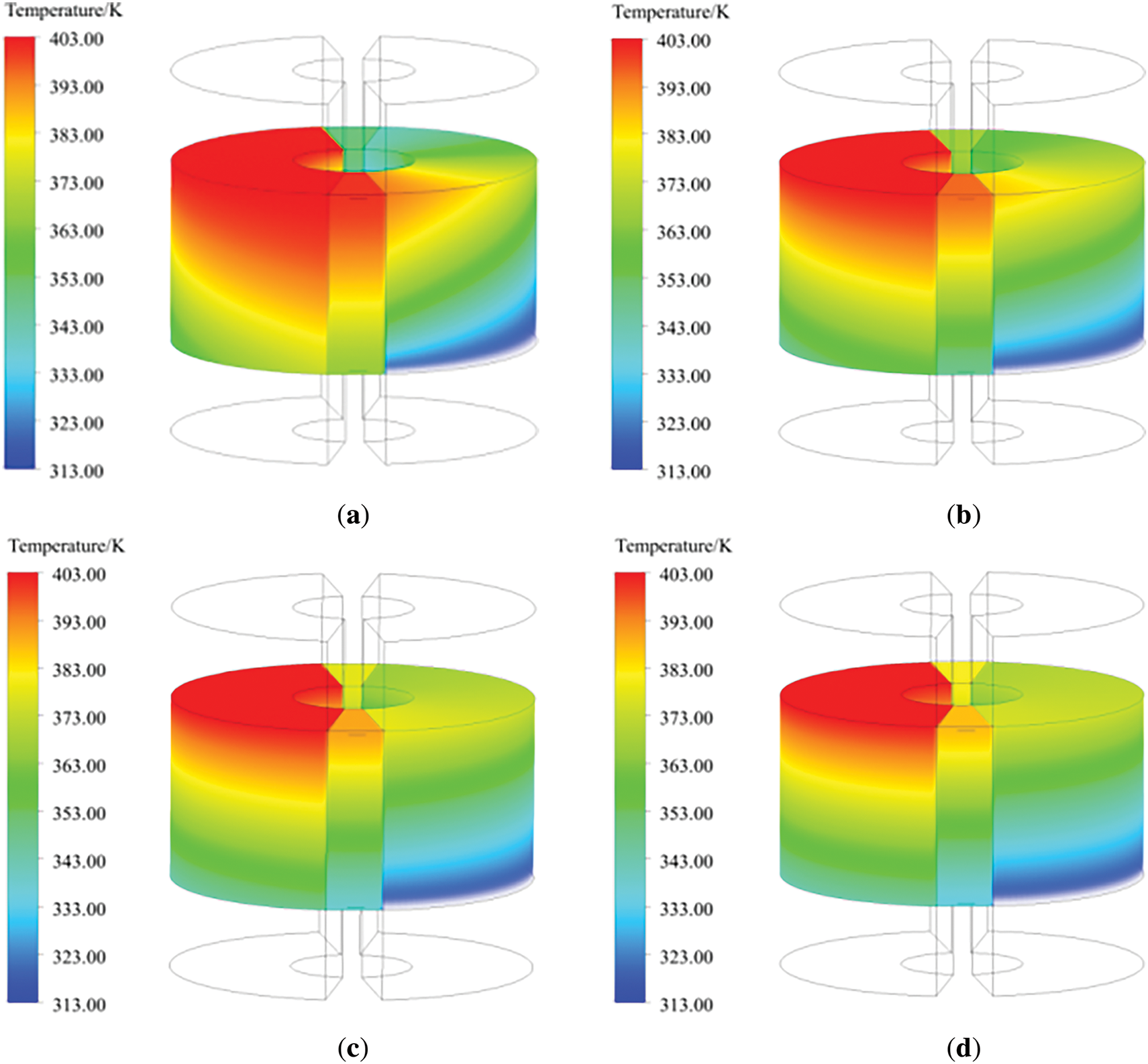
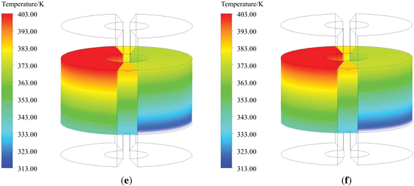
Figure 5: Gas temperature distribution inside the rotary GGH rotor. (a) 0.1 rpm; (b) 0.2 rpm; (c) 0.5 rpm; (d) 1 rpm; (e) 1.5 rpm; (f) 2.5 rpm
The temperature distribution on one side of the metal matrix is shown in Fig. 6, which shows significant differences compared to the gas temperature distribution. This indicates the existence of a non thermal equilibrium phenomenon between the matrix and the gas, thus proving the rationality of using a porous medium non thermal equilibrium model. From Fig. 6, it can be seen that the metal heating surface on the low-temperature flue gas purification side is cooled and absorbed by the flue gas, and the temperature gradually decreases along the rotation direction. At low speeds, the supercooling area of the metal heating surface is larger. As the speed increases, the temperature of the metal heating surface becomes more uniform within the rotation range, indicating that increasing the speed can improve the heat transfer effect.
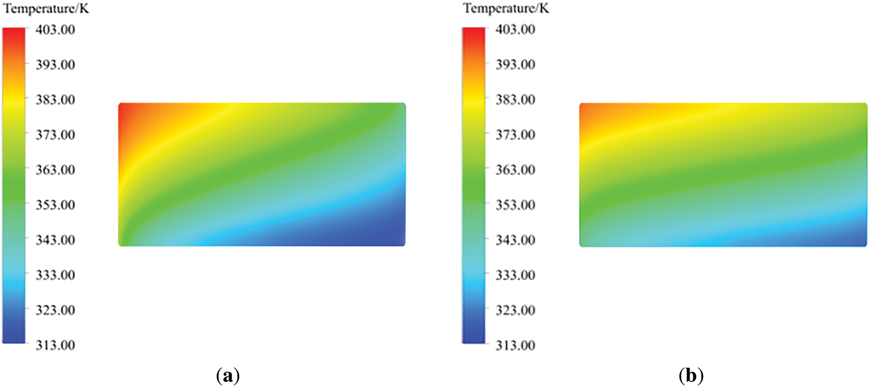
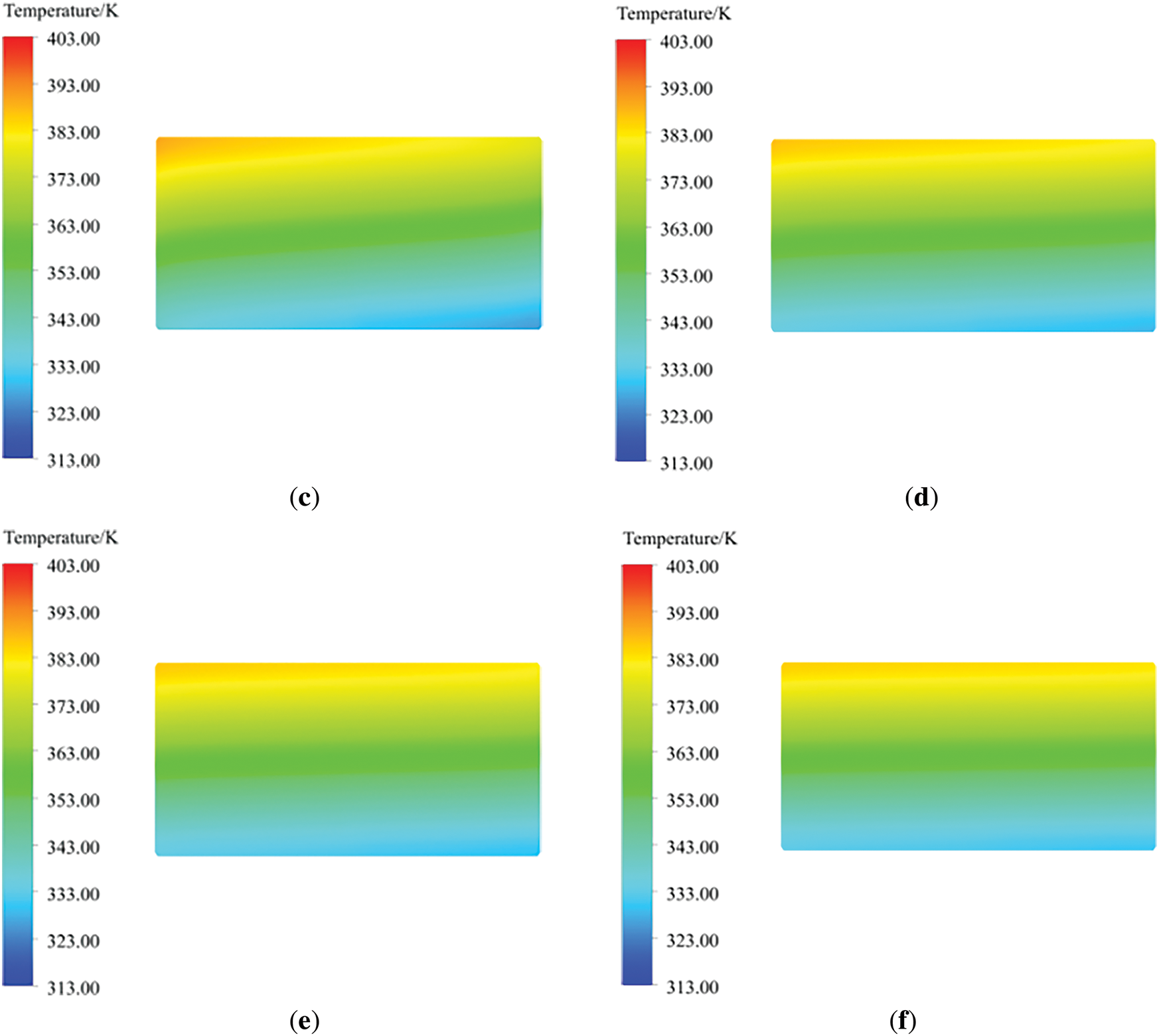
Figure 6: Temperature distribution diagram of rotary GGH metal heat exchange surface. (a) 0.1 rpm; (b) 0.2 rpm; (c) 0.5 rpm; (d) 1 rpm; (e) 1.5 rpm; (f) 2.5 rpm
Starting from the untreated flue gas side of the rotary GGH, take heights of 0, 50, 100, 150, 200, 250, and 300 mm, respectively, and read the temperature distribution of the metal heat exchange surface rotating one revolution along the rotor. As shown in Fig. 7, with the sealing zone as the starting point of rotation, the heat exchange element is heated and heated as the rotor rotates on the high-temperature untreated flue gas side. Due to the constant speed rotation of the rotor, the temperature of the metal substrate changes continuously. When the rotor rotates to the next sealing zone, the temperature of the metal substrate hardly changes due to the lack of external working fluid circulation. When the heat exchange element rotates with the rotor to the purified flue gas side, it transfers heat to the low-temperature purified flue gas, resulting in a uniform decrease in the temperature of the metal wall. Comparing the temperature distribution of the metal matrix of the rotary GGH at different speeds shown in Figs. 7 and 8, it can be seen that as the speed decreases, the temperature span of the metal wall surface in the height direction of the rotor is larger, and the temperature change slope of the metal wall surface along the rotation direction is larger. This is because increasing the speed increases the frequency of heat exchange between the heat exchange element and the flue gas, and the temperature change of the heat exchange element becomes smoother under the repeated alternating flushing of cold and heat flows. This law corresponds to the temperature distribution law obtained in Fig. 6 and is consistent with the conclusion proposed in reference [24], proving that the use of a multiple reference frame model can achieve the heat transfer process of rotary GGH at different speeds.
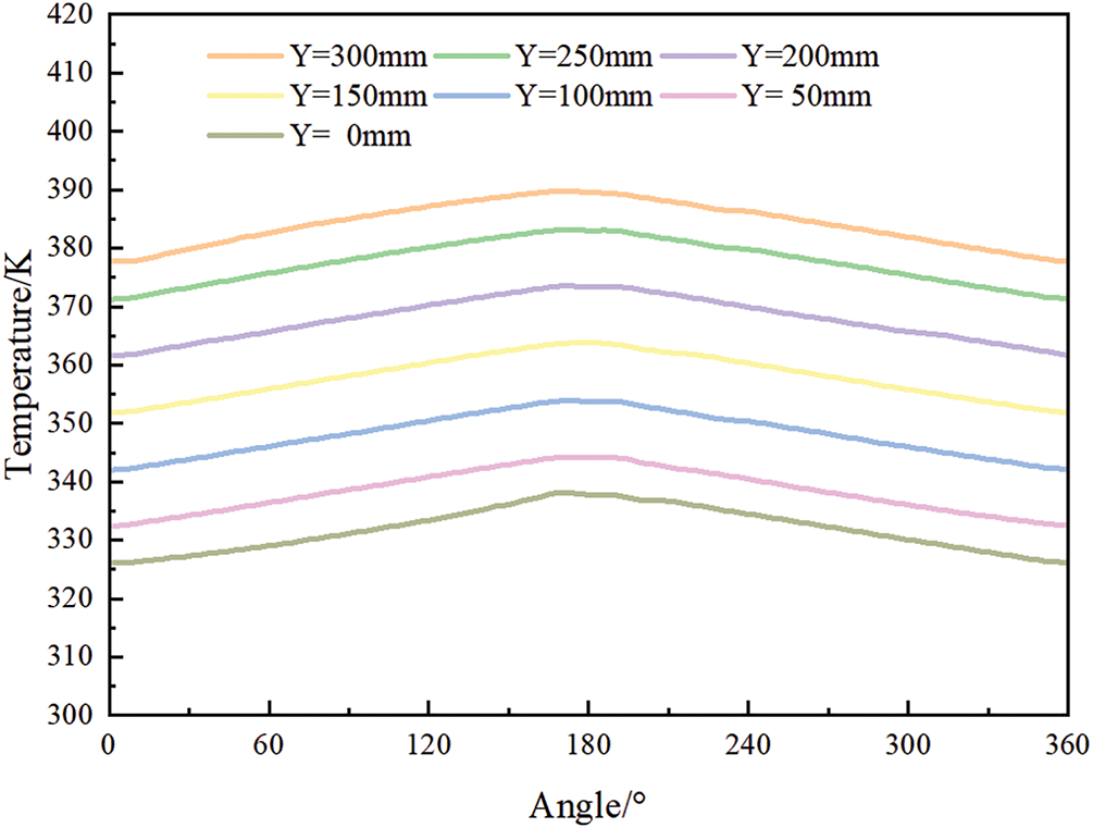
Figure 7: Circumferential temperature of metal heating surface at a speed of 0.5 rpm
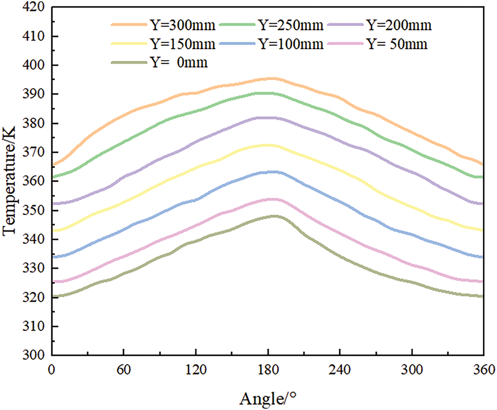
Figure 8: Circumferential temperature of metal heating surface at a speed of 0.2 rpm
Figs. 9 and 10 show the distribution of outlet temperatures at the hot and cold ends of a rotary GGH. The outlet flue gas temperature undergoes significant changes in the rotational direction, while remaining almost unchanged in the radial direction.
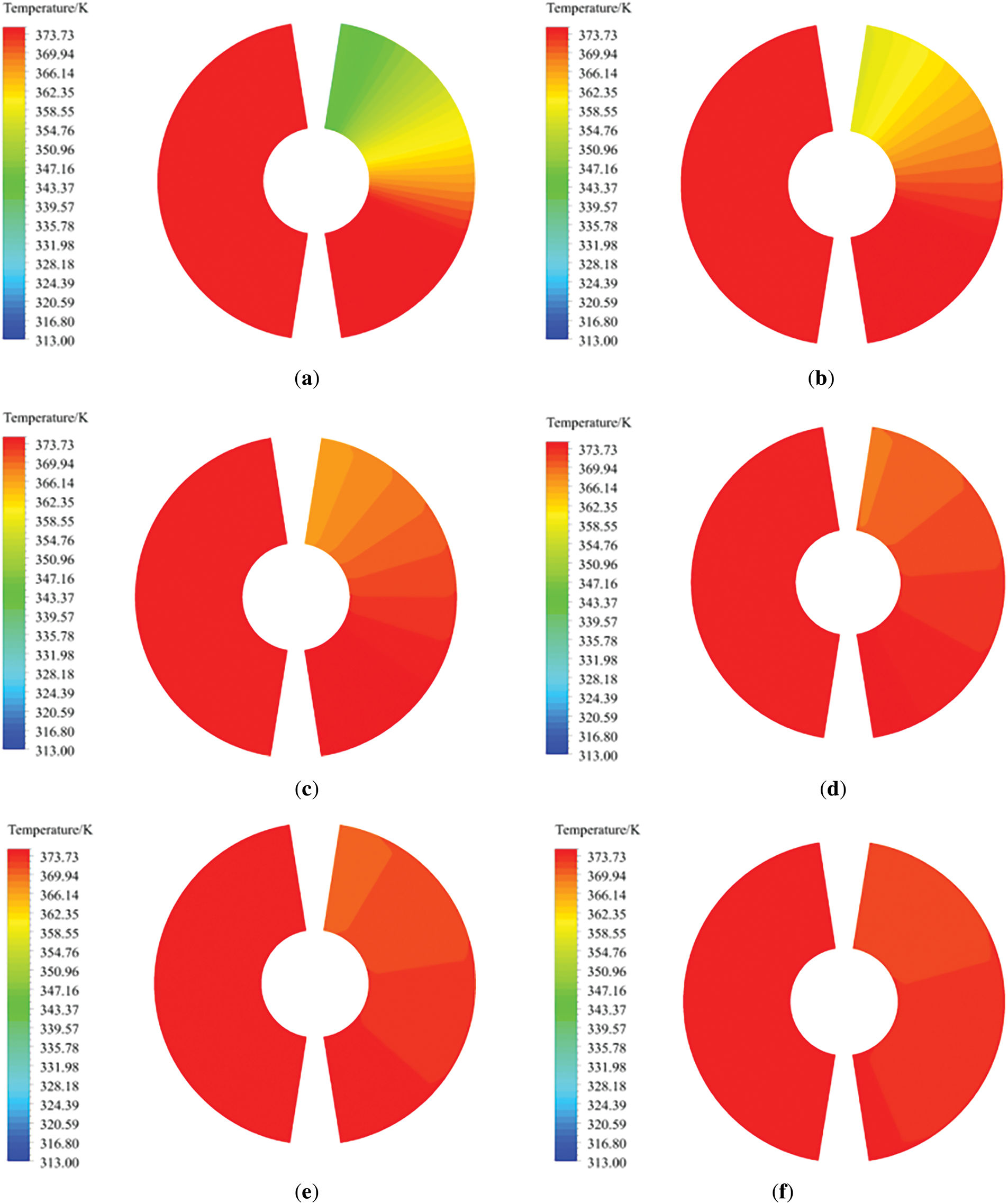
Figure 9: Temperature distribution diagram of rotary GGH hot end. (a) 0.1 rpm; (b) 0.2 rpm; (c) 0.5 rpm; (d) 1 rpm; (e) 1.5 rpm; (f) 2.5 rpm
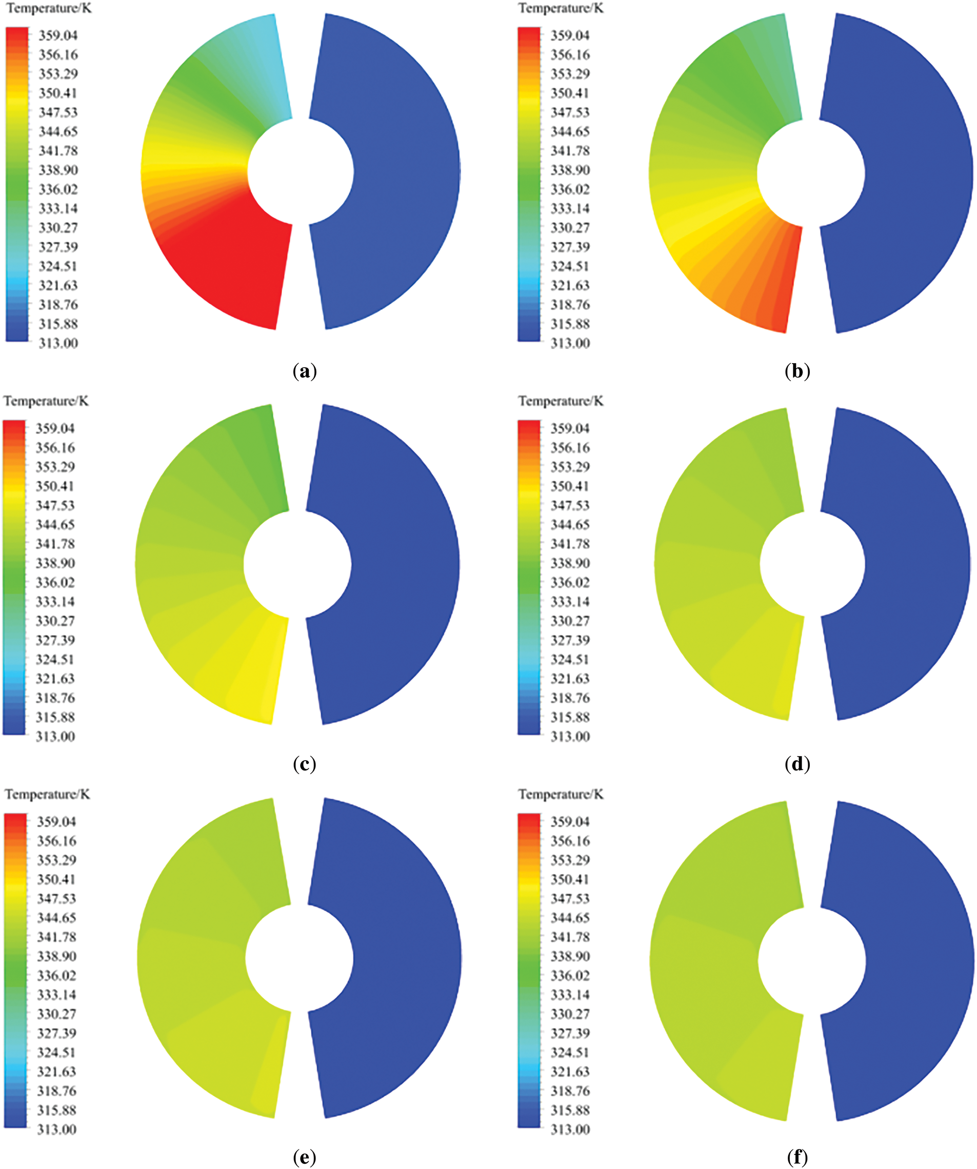
Figure 10: Temperature distribution diagram of rotary GGH cold end. (a) 0.1 rpm; (b) 0.2 rpm; (c) 0.5 rpm; (d) 1 rpm; (e) 1.5 rpm; (f) 2.5 rpm
As shown in Fig. 9, the heat exchange element on the clean flue gas side transfers heat to the low-temperature clean flue gas, causing its temperature to rise. When the rotor enters the starting position of the clean flue gas area, the heat exchange element absorbs the heat of the original flue gas and heats the clean flue gas to a high temperature due to the high metal wall temperature. During the rotation of the rotor, the heat exchange element continuously exchanges heat with the clean flue gas. As the rotation angle increases, the temperature difference between the heat exchange element and the clean flue gas gradually decreases, so the outlet temperature of the clean flue gas gradually decreases along with the rotation direction. For the untreated flue gas side as shown in Fig. 10, at low speeds, the contact time between the heat exchange element and the high-temperature untreated flue gas is longer during the rotation cycle. At the beginning of rotation, the flue gas temperature decreases significantly. In the direction of rotation, the heat exchange element approaches the high-temperature flue gas temperature faster at low speeds than at high speeds. After the rotor rotates to a certain position, the heat transferred from the high-temperature flue gas to the heat exchange element is less. Therefore, at the same rotation position, the outlet temperature of the high-temperature untreated flue gas corresponding to low speeds is higher.
The circumferential temperature distribution curves of purified and untreated flue gas outlets are shown in Figs. 11 and 12. The temperature fluctuations of the flue gas on both sides within the rotation angle range increase with the decrease of the rotational speed, which is consistent with the law given in reference [28].
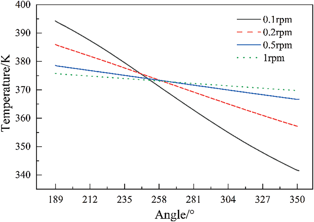
Figure 11: Distribution of circumferential temperature at the outlet of purified flue gas
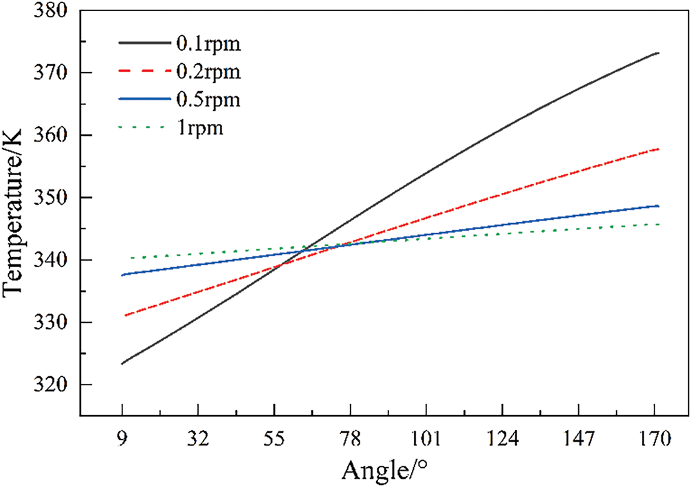
Figure 12: Distribution of circumferential temperature at the outlet of untreated flue gas
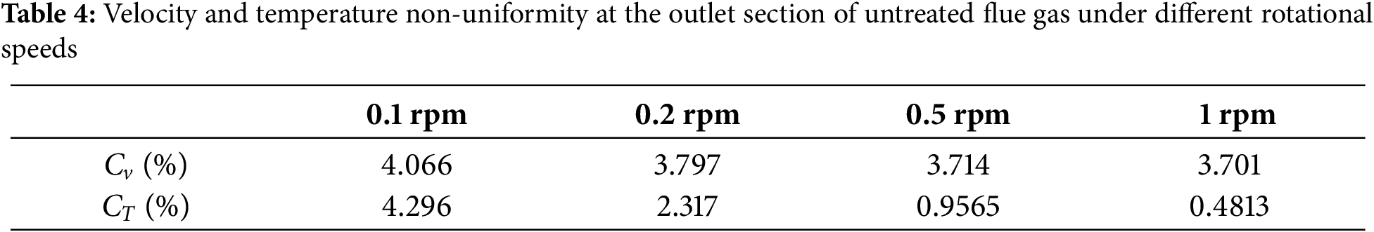
In the waste heat recovery system, the rotary GGH untreated flue gas side outlet is connected with the decontamination equipment. Therefore, the more uniform the velocity and temperature distribution of the untreated flue gas outlet is, the more conducive it is to the operation of the overall system. The uniformity of wind speed at the outlet section of untreated flue gas can be expressed by the relative standard deviation of velocity Cv [29], and the uniformity of temperature can be expressed by the relative standard deviation of temperature CT. The calculation formula is as follows, and the results are shown in Table 4. It can be seen that the flue gas outlet temperature and velocity distribution are more uniform with the increase of rotating speed.
where, sv is the standard deviation of speed,
The rotary GGH is simplified by using the porous media model, and the basic parameters of porous media are given. Model validation was performed through comparison with published reference data. Analysis of the internal temperature field further confirms the model’s accuracy and elucidates heat transfer mechanisms in rotary GGH, yielding the following conclusions:
1. The calculation method of porosity is determined according to the arrangement characteristics of heat exchange elements in rotary GGH; The formula of resistance law in the porous region is derived, and the channel model of the heat exchange element corresponding to the studied rotary GGH is established. The fitting formula of pressure drops varying with velocity is obtained. Comparative analysis with empirical formulations yielded viscous and inertial resistance coefficients for the porous medium.
2. According to the internal solid framework of porous media and the temperature difference between working fluids, the speed of flow rate of working fluids, and the large differences between the rotary GGH metal heat exchanger and the physical parameters between working fluids, the non-thermal equilibrium model of porous media was selected for simulation; MRF model was used to simulate the rotating process of rotary GGH.
3. Compared with the calculation model of rotary GGH in literature, the relative error is less than 5%. The rotary GGH temperature field was analyzed. The rotating speed increased from 0.1 to 1 rpm, and the temperature nonuniformity coefficient decreased from 4.296 to 0.4813; When the rotor rotates at a uniform speed, the metal heating surface and flue gas temperature are evenly distributed, and the internal temperature distribution of the rotary GGH changes when the speed changes. It shows that the selected model can truly reflect the rotary heat transfer process of rotary GGH.
4. This article simplifies the flue gas to standard flue gas for research, considering that the low-temperature denitrification system in cement kilns contains bag filters and desulfurization equipment. However, in actual engineering operation, there may still be trace amounts of dust and SO2 components in the flue gas. In future research, consideration can be given to issues such as dust accumulation and corrosion in rotary GGH.
Acknowledgement: Not applicable.
Funding Statement: This study was financially supported the Eco-Environment Project of the Key Research and Development Program of Anhui Province (No. 202104i07020016).
Author Contributions: The authors confirm contribution to the paper as follows: methodology, Chen Zhu and Yi Sun; software, Chen Zhu and Qi Ma; validation, Chen Zhu, Xiao Ma and Yi Sun; formal analysis, Chen Zhu and Lumin Chen; investigation, Chen Zhu, Xiao Ma, Lumin Chen and Yi Sun; resources, Fuping Qian; data curation, Chen Zhu and Lumin Chen; writing—original draft preparation, Chen Zhu, Yi Sun and Lumin Chen; writing—review and editing, Chen Zhu, Xiao Ma, Qi Ma and Lumin Chen; supervision, Fuping Qian; funding acquisition, Fuping Qian. All authors reviewed the results and approved the final version of the manuscript.
Availability of Data and Materials: Data available on request from the authors.
Ethics Approval: Not applicable.
Conflicts of Interest: The authors declare no conflicts of interest to report regarding the present study.
References
1. Gao Y, Qian F, Sun Y, Wu Y, Wu S, Lu J, et al. A model for predicting the erosion rate induced by the use of a selective catalytic reduction denitrification technology in cement kilns flue gas. Fluid Dyn Mater Process. 2023;19(8):1997–2011. doi:10.32604/fdmp.2023.026373. [Google Scholar] [CrossRef]
2. Wang L, Bu Y, Li D, Tang C, Che D. Single and multi-objective optimizations of rotary regenerative air preheater for coal-fired power plant considering the ammonium bisulfate deposition. Int J Therm Sci. 2019;136(8):52–9. doi:10.1016/j.ijthermalsci.2018.10.005; [Google Scholar] [CrossRef]
3. Özdemir K, Serincan MF. A computational fluid dynamics model of a rotary regenerative heat exchanger in a flue gas desulfurization system. Appl Therm Eng. 2018;143(1):988–1002. doi:10.1016/j.applthermaleng.2018.08.011. [Google Scholar] [CrossRef]
4. Wang L, Li D, Zhu H, Chen G, Luo H, Che D. Investigation on regenerative heat exchanger with novel low-leakage system for flue gas denitration in steel industry. Appl Therm Eng. 2020;178:115483. doi:10.1016/j.applthermaleng.2020.115483. [Google Scholar] [CrossRef]
5. Wang HY, Zhao LL, Xu ZG, Chun WG, Kim HT. The study on heat transfer model of tri-sectional rotary air preheater based on the semi-analytical method. Appl Therm Eng. 2008;28(14–15):1882–8. doi:10.1016/j.applthermaleng.2007.11.023. [Google Scholar] [CrossRef]
6. Mioralli PC, Ganzarolli MM. Thermal analysis of a rotary regenerator with fixed pressure drop or fixed pumping power. Appl Therm Eng. 2013;52(1):187–97. doi:10.1016/j.applthermaleng.2012.11.030. [Google Scholar] [CrossRef]
Padhi MR, Ghose P. Performance prediction of a model rotary air preheater through porous media approach. J Therm Sci Eng Appl. 2023;15(7):071008. doi:10.1115/1.4062315. [Google Scholar] [CrossRef]
8. Bu Y, Wang L, Zhu H, Pu H, Wei Y, Che D. Numerical analysis of the coupling between heat transfer and deformation in rotary air preheater. Int J Heat Mass Transf. 2021;165(6):120625. doi:10.1016/j.ijheatmasstransfer.2020.120625. [Google Scholar] [CrossRef]
9. Hajebzadeh H, Ansari AN. Modification of rotary air preheater toward achieving extended life-span utilizing porous media approach: a case study. J Power Energy. 2022;236(2):293–307. doi:10.1177/09576509211034977. [Google Scholar] [CrossRef]
10. Yang K, Li X, Liu K, Wang J. Coupling effect of heat transfer in plate heat exchanger filled with porous media. Int J Heat Mass Transf. 2022;182(1):121966. doi:10.1016/j.ijheatmasstransfer.2021.121966. [Google Scholar] [CrossRef]
11. Shang XS, Gong H, Zeng XX, Wang BC, Cao HQ, Shao W, et al. Effects of geometric structures on the sub-Kelvin porous media heat exchanger. Int J Refrig. 2024;160:207–16. doi:10.1016/j.ijrefrig.2024.02.012; [Google Scholar] [CrossRef]
12. Dallaire J, Gosselin L, da Silva AK. Conceptual optimization of a rotary heat exchanger with a porous core. Int J Therm Sci. 2010;49(2):454–62. doi:10.1016/j.ijthermalsci.2009.07.027. [Google Scholar] [CrossRef]
13. Alhusseny A, Turan A. An effective engineering computational procedure to analyse and design rotary regenerators using a porous media approach. Int J Heat Mass Transf. 2016;95(2):593–605. doi:10.1016/j.ijheatmasstransfer.2015.12.033. [Google Scholar] [CrossRef]
14. Chen Z, Li H, Gu Y, Zhu W. A novel flexible seal technology and its application in heat transfer of rotary air preheater. Appl Therm Eng. 2019;163:114414. doi:10.1016/j.applthermaleng.2019.114414; [Google Scholar] [CrossRef]
15. Sphaier LA, Worek WM. Analysis of heat and mass transfer in porous sorbents used in rotary regenerators. Int J Heat Mass Transf. 2004;47(14–16):3415–30. doi:10.1016/j.ijheatmasstransfer.2004.01.016. [Google Scholar] [CrossRef]
16. Li Y, Wei H, Fan C, Shi W. A novel numerical simulation study of air leakage in rotary air preheaters based on rotor thermal deformation. Processes. 2024;12(3):505. doi:10.3390/pr12030505. [Google Scholar] [CrossRef]
17. Drobnič B, Oman J, Tuma M. A numerical model for the analyses of heat transfer and leakages in a rotary air preheater. Int J Heat Mass Transf. 2006;49(25–26):5001–9. doi:10.1016/j.ijheatmasstransfer.2006.05.027. [Google Scholar] [CrossRef]
18. Zhang X, Yuan J, Tian Z, Wang J. Estimation of the direct leakage of rotary air preheaters based on temperature distribution modeling. Int J Heat Mass Transf. 2019;134:119–30. doi:10.1016/j.ijheatmasstransfer.2018.12.172; [Google Scholar] [CrossRef]
19. Bu Y, Wang L, Deng L, Che D. Technical and economical analysis of a novel rotary air preheater system. Appl Therm Eng. 2019;154:102–10. doi:10.1016/j.applthermaleng.2019.03.007; [Google Scholar] [CrossRef]
20. Ben Nasrallah S, Ben Khedher N. Three-dimensional simulation of a porous thermal energy storage system using solid-liquid phase change material. J Por Media. 2011;14(9):777–90. doi:10.1615/jpormedia.v14.i9.30. [Google Scholar] [CrossRef]
21. Rashidi S, Kashefi MH, Kim KC, Samimi-Abianeh O. Potentials of porous materials for energy management in heat exchangers—a comprehensive review. Appl Energy. 2019;243(12):206–32. doi:10.1016/j.apenergy.2019.03.200. [Google Scholar] [CrossRef]
22. Sun Y, Qian F, Yu LT, Wu Y, Huang N, Wu H. Numerical study on heat transfer and resistance characteristics of heattransfer element of rotary heat exchanger. Chin J Process Eng. 2024;24(6):670–80. (In Chinese). [Google Scholar]
23. Heidari-Kaydan A, Hajidavalloo E. Three-dimensional simulation of rotary air preheater in steam power plant. Appl Therm Eng. 2014;73(1):399–407. doi:10.1016/j.applthermaleng.2014.08.013; [Google Scholar] [CrossRef]
24. Dehghan M, Valipour MS, Keshmiri A, Saedodin S, Shokri N. On the thermally developing forced convection through a porous material under the local thermal non-equilibrium condition: an analytical study. Int J Heat Mass Transf. 2016;92(5):815–23. doi:10.1016/j.ijheatmasstransfer.2015.08.091. [Google Scholar] [CrossRef]
25. Paz C, Suárez E, Conde M, Vence J. Development of a computational fluid dynamics model for predicting fouling process using dynamic mesh model. Heat Transf Eng. 2020;41(2):199–207. doi:10.1080/01457632.2018.1522108. [Google Scholar] [CrossRef]
26. Far EK, Geier M, Krafczyk M. Simulation of rotating objects in fluids with the cumulant lattice Boltzmann model on sliding meshes. Comput Math Appl. 2020;79(1):3–16. doi:10.1016/j.camwa.2018.08.055. [Google Scholar] [CrossRef]
27. Zelenský P, Zmrhal V, Barták M, Kučera M. Simulation-aided development of a compact local ventilation unit with the use of CFD analysis. Build Simul. 2024;17(12):2233–47. doi:10.1007/s12273-024-1183-9; [Google Scholar] [CrossRef]
28. Wang L, Wang C, Guo Y, Wu Y, Bai W, Che D. Novel rotary regenerative heat exchanger using cascaded phase change material capsules. Appl Therm Eng. 2021;188(3):116619. doi:10.1016/j.applthermaleng.2021.116619. [Google Scholar] [CrossRef]
29. Cao B, Qian F, Liu Z, Wang L, Xu B, Huang N, et al. Flow field simulation and structure optimization on desulfurization-dust removal-denitrification system of sintering flue gas. J China Coal Soc. 2020;45(10):3589–99. (In Chinese). doi:10.1007/978-3-031-50184-5_23. [Google Scholar] [CrossRef]
Cite This Article
 Copyright © 2025 The Author(s). Published by Tech Science Press.
This work is licensed under a Creative Commons Attribution 4.0 International License , which permits unrestricted use, distribution, and reproduction in any medium, provided the original work is properly cited.
 Downloads
 Citation Tools