
 Submit a Paper
 Propose a Special lssue
 Open Access
ARTICLE

Numerical Simulation on Heat Dissipation Characteristics of Electronic Components with Different Heat Sink Arrangements in High-Performance Server
China Southern Power Grid, Electric Power Research Institute of Guizhou Power Grid Co., Ltd., Guiyang, 550002, China
* Corresponding Author: Zerui Chen. Email:
Frontiers in Heat and Mass Transfer 2025, 23(3), 991-1011. https://doi.org/10.32604/fhmt.2025.065936
Received 25 March 2025; Accepted 09 May 2025; Issue published 30 June 2025
 View Full Text
 Download PDF
Abstract
As the integration of electronic components in high-performance servers increases, heat generation significantly impacts performance and raises failure rates. Therefore, heat dissipation has become a critical concern in electronic circuit design. This study uses numerical simulations to investigate the heat dissipation characteristics of electronic components in air-cooled servers. By adjusting airflow speed, heat sink configurations, and the arrangement of straight-fin heat sinks, we optimize heat dissipation performance and analyze the mechanisms at different airflow speeds. The results show that, at the same airflow speed, the temperature of the heat sink is lower than that of the electronic components, creating a temperature gradient that enhances heat transfer. Compared to a front-to-back arrangement of two straight-fin heat sinks, placing the heat sinks parallel to each other results in a lower maximum component temperature and better temperature uniformity. Heat sinks with fins significantly improve heat dissipation. The heat sink with semicylindrical fins on the rib surface provides the best cooling performance. Moreover, compared to natural convection, the maximum temperature of the electronic components decreases by 56.17% and 61% when the incoming flow velocity is 6 m/s with two parallel flat ribbed heat sinks and front-to-back arrangement, respectively.Keywords
As the integration of electronic components in high-performance servers increases, the heat generated grows exponentially, raising demands on heat sink performance [1,2]. Most of the electrical energy lost in electronic components is converted into heat, significantly raising their operating temperature. Prolonged exposure to high temperatures can drastically degrade component performance and stability, leading to a significant increase in failure rates [3,4]. While performance remains largely unaffected when the operating temperature is below 80°C, it deteriorates rapidly once the temperature exceeds 80°C, necessitating heat dissipation for high-temperature areas [5,6]. Therefore, heat dissipation has become a critical factor in the integration of electronic circuits.
Cooling methods in electronic devices are classified into direct-contact and indirect-contact types based on the interaction between the cooling medium and the device. Direct-contact methods include air cooling, spray cooling, jet impingement cooling, and immersion cooling [7–11]. Tari and Mehrtash [12] and Ke et al. [13] identified flow separation in heat sink fin channels as a primary factor affecting heat transfer performance. Muneeshwaran et al. [14] proposed a gap-type fin heat sink with a central opening to enhance heat transfer under natural convection. This design reduces the heat transfer surface area, directs more airflow into the fin area, and lowers thermal resistance by 13%. Huang and Chen [15] optimized the fin shape, identifying the optimal geometry for a Y-type displacement heat sink to minimize the average temperature. By adjusting the displacement distance, the optimized Y-type heat sink features upward-displaced fins, which enhance the chimney effect from buoyant airflow and generate larger longitudinal vortices. This improves contact between the heat sink surface and air, thereby enhancing heat dissipation. Abbas and Wang [16] found that vertical displacement of the fins under natural convection delays the merging of thermal boundary layers between consecutive fins, reducing thermal resistance by up to 60%. Ahmadi et al. [17] studied steady-state external natural convection heat transfer for vertically mounted rectangular interrupted fins. They observed that introducing interruptions significantly improved thermal performance, with an optimal fin interruption. Mousavi et al. [18] numerically studied 10 different types of interrupted, staggered, and covered fin heat sinks for radiation and natural convection heat transfer. They concluded that reducing fin spacing below 3 mm in a staggered configuration did not improve cooling, while L-shaped cut fins achieved the lowest temperature without adding extra weight.
Gurav et al. [19] analyzed the flow and thermal characteristics of rotating airfoils, single-layer, and double-layer micro-pin fins. They found that the Nusselt number (Nu) was higher for double-layer pins, indicating improved heat transfer. Additionally, Nu increased with Reynolds number (Re), enhancing heat transfer from the CPU and lowering its temperature. Naphon et al. [20] studied the heat transfer performance of integrated and segmented straight-fin heat sinks. Their results showed that, under the same heating power and flow rate conditions, the heat transfer coefficient of the segmented heat sink was twice that of the integrated straight type. Khudhur et al. [21] proposed that adding or removing fins from traditional flat heat sinks altered thermal performance and fluid dynamics, thereby improving heat transfer. Li and Wu [22] showed that the heat transfer efficiency of pin fin heat sinks cooled by two piezoelectric fans decreased with increasing fan height, while thermal resistance decreased with fan width, and the rate of change in thermal resistance decreased as width increased. Sufian and Abdullah [23] designed a combined piezoelectric fan and radiator to enhance heat transfer in light-emitting diodes (LEDs). Compared to natural convection, the dual-vibration fan heat sinks improved heat transfer performance by approximately 3.3 times, while the quadruple-vibration fan heat sinks enhanced LED cooling by 2.3 times. Shan et al. [24] found that the heat transfer performance of electronic heat sinks is related to the number of fins, and the heat transfer coefficient increases and then decreases as the number of fins increases. Nair et al. [25] mentioned in their latest review work, that although a variety of novel electronic thermal management techniques this year have been developed, air-cooled heat sinks remain one of the most widely adopted thermal management techniques in the industry due to their broad compatibility with electronic components and reliability. Hussein et al. [26] investigated numerically the effect of new tile fin geometries on its thermal performance in a heat sink under natural convection conditions. They found that the new fins configurations dissipated heat more than the flat one. The simulation results of Yu et al. [27] demonstrated that the flow velocity and fin transverse width were the main factors affecting heat transfer and fluid flow. While previous studies have extensively explored various heat sink configurations for electronic components, there is a paucity of research focusing on the impact of different heat sink arrangements within high-performance servers under realistic airflow conditions. Our study aims to fill this gap by numerically investigating the heat dissipation characteristics of electronic components with different heat sink arrangements in a high-performance server environment.
In summary, while several studies have focused on enhancing the heat dissipation performance of electronic components through innovative heat sink designs, the efficiency of heat dissipation under varying convection conditions and the significant increase in flow resistance caused by structural changes to the heat sink remains limited. To advance this field, further research is needed to optimize heat sink designs and airflow conditions for improved heat dissipation efficiency and comprehensive performance evaluation. Therefore, this study uses Fluent to investigate the heat dissipation mechanisms of electronic components at different incoming flow velocities, as well as the impact of heat sink layout and structure on dissipation efficiency.
This paper provides new insights into the layout of heat sinks and the geometry of heat sinks under different airflow conditions and resolves the limitations in existing studies. Specifically, we highlight the following contributions:
(1) Novel Heat Sink Configurations: we explore unconventional arrangements, such as inline dual heat sinks, and analyze their impact on thermal performance, providing insights not extensively covered in prior research.
(2) Comprehensive Fin Geometry Analysis: our study evaluates various fin geometries, including twisted blade-like fins, under different airflow conditions, demonstrating their effectiveness in enhancing heat transfer while minimizing pressure drop.
(3) Integration of Numerical and Experimental Methods: we employ both computational fluid dynamics simulations and experimental validations to ensure the reliability of our findings, addressing the gap between theoretical models and practical applications.
The flow and heat dissipation of air within the enclosure housing electronic components are governed by the continuity, momentum, and energy equations. While the air exhibits laminar flow under natural convection, the application of incoming flow velocity induces turbulent phenomena, such as flow separation, vortices, and secondary flows, as the air passes over the heat sinks. The Realizable k-epsilon model, which more accurately predicts these turbulent phenomena, is therefore selected for this study.
(1) Continuity Equation:
In the equation:
(2) Momentum Equation:
In the equation:
(3) Energy Equation:
In the equation:
(4) Realizable k-epsilon Turbulence Model:
In the Realizable k-epsilon equations, the values of the constants are as follows:
(5) Calculation of Thermal Resistance:
where
Fig. 1 shows the geometric model of a rectangular computational domain, with dimensions of 1000 × 360 × 200 mm, and the size of the Printed Circuit Board (PCB) 1000 × 360 × 6 mm. Within this region, a heat sink is centrally located 200 mm from the air inlet, with the lower surface of the heat sink’s base plate connected to the electronic component. The sizes of the electronic components are 160 × 123 × 6 mm.
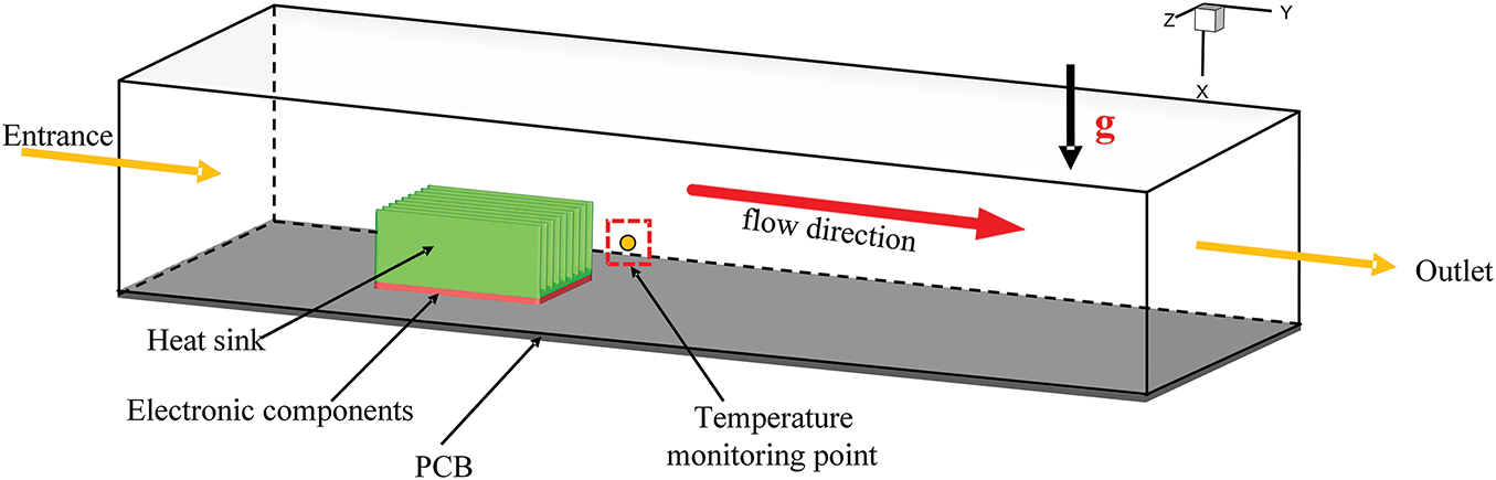
Figure 1: Geometric model of electronic component heat dissipation
This paper employs three distinct types of heat sinks, a flat ribbed heat sink (Fig. 2a), a heat sink with triangular prism-shaped fins on the rib surface (Fig. 2b), and a heat sink with semicircular winglets on the rib surface (Fig. 2c). The geometric parameters of these heat sinks are summarized in Table 1.
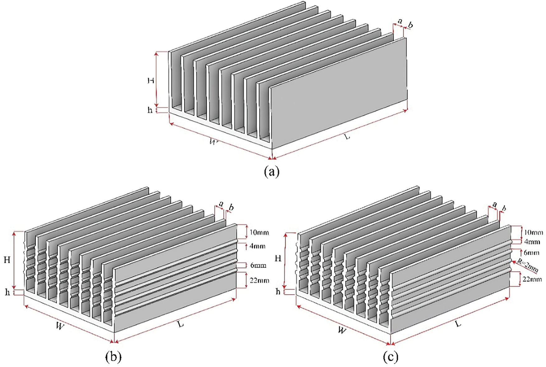
Figure 2: Geometric model of heat sinks. (a) A flat ribbed heat sink, (b) a heat sink with triangular prism-shaped fins on the rib surface, (c) a heat sink with semicircular winglets on the rib surface
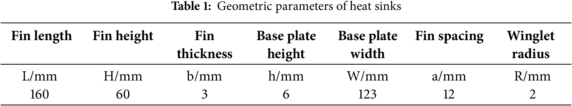
Fig. 3 shows the mesh models of three types of heat sinks. The flat ribbed heat sink uses a tetrahedral mesh, while the heat sink with triangular prism-shaped fins and the heat sink with semicircular winglets on the fin surface, due to their more complex structures, utilize a mosaic mesh.
Figure 3: Mesh of the three types of heat sink structures. (a) Flat ribbeb heat sink; (b) Heat sink with semicircular winglets on the fin surface; (c) Heat sink with trangular prism-shaped fins on the fin surface
2.4 Boundary Conditions and Solving Method
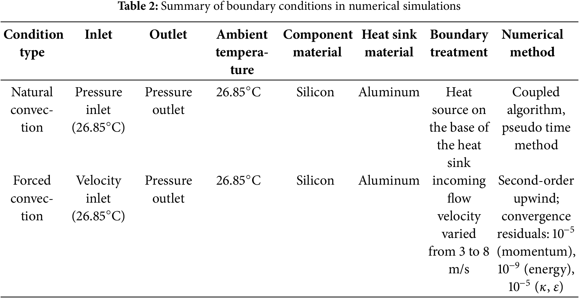
In the numerical simulation, natural convection for electronic component heat dissipation is modeled with the inlet defined as a pressure boundary and the outlet as a pressure outlet. The uniform power consumption on the surface of electronic components is simulated by using the constant heat flow boundary condition. Both the inlet air temperature and the enclosure’s ambient temperature are set to 26.85°C. When simulating forced convection with increased incoming flow velocity, the inlet is configured as a velocity inlet while the outlet remains a pressure outlet. The heat sink is modeled as aluminum, and the electronic components are modeled as silicon to replicate actual heat dissipation conditions. The coupled algorithm and pseudo-time methods are used for pressure-velocity coupling, with the energy and momentum equations discretized using the Second Order Upwind method. The convergence criteria are set to 10−5 for the continuity and momentum equations, 10−9 for the energy equation, and 10−5 for the k and έ equations. The boundary conditions in numerical simulation are summarized as shown in Table 2. Additionally, a monitoring point at coordinates (−0.05, 0.1, 0) is placed to track air temperature variations behind the heat sink.
2.5 Grid Independence and Model Validation
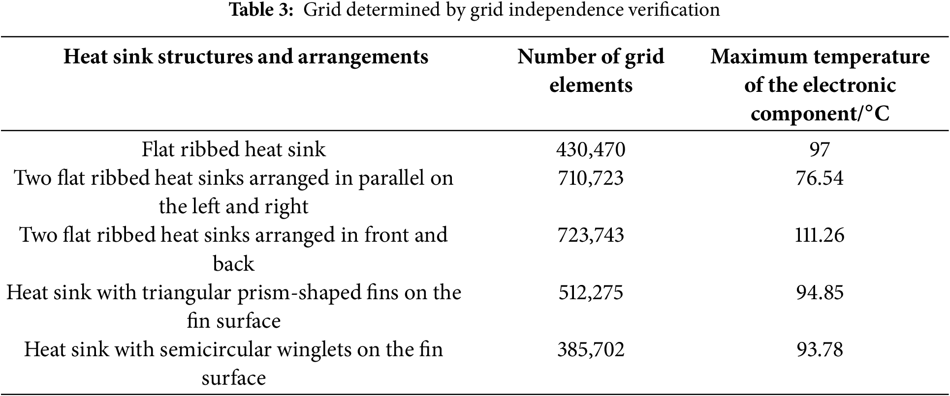
The flow field within the computational domain is highly complex. Tetrahedral meshes are applied to simulate the heat dissipation of electronic components using flat-fin heat sinks. For more intricate heat sink designs, such as those with triangular prism-shaped or semicylindrical fins, mosaic meshes are employed to balance accuracy and reduce the total number of cells. Grid refinement beyond a certain level does not significantly affect the maximum temperature of electronic components, confirming that the current mesh count satisfies accuracy requirements. Fig. 4 illustrates the relationship between mesh count and the maximum temperature of electronic components under natural convection for different heat sink structures and configurations. Since the operating temperature of the electronic components involved in the research in a typical server is usually below 120°C, the contribution of radiative heat transfer is relatively small. This paper mainly considers natural convection and forced convection as the dominant heat transfer mechanisms in the cooling process of electronic devices. Therefore, radiation is not included as an explicit boundary condition in the model, which has also been demonstrated in previous studies [27,28]. The final mesh counts for each case are summarized in Table 3.
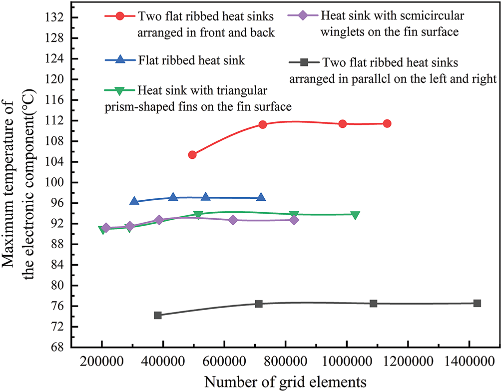
Figure 4: Grid independence verification
To verify the accuracy of the model, the simulation results were compared with the experimental data provided by Kanargi et al. [29], as illustrated in Fig. 5. The computational domain, heater power (20 W), and the airflow velocities in our simulations were set to match the experimental conditions reported in the referenced study [29]. However, the experimental data available in that work are limited, as measurements were conducted only under moderate Reynolds number conditions, resulting in a relatively small number of data points. As seen, the light blue region represents the 5% error margin of the experimental results. At a Reynolds number of 2727 (0.5 m/s), the error between the simulation and experimental data is 3.38%. For Reynolds numbers 4363 (0.8 m/s) and 5454 (1.0 m/s), the errors are 1.4% and 1.95%, respectively. All discrepancies fall within the acceptable error range, demonstrating the model’s accuracy and reliability.
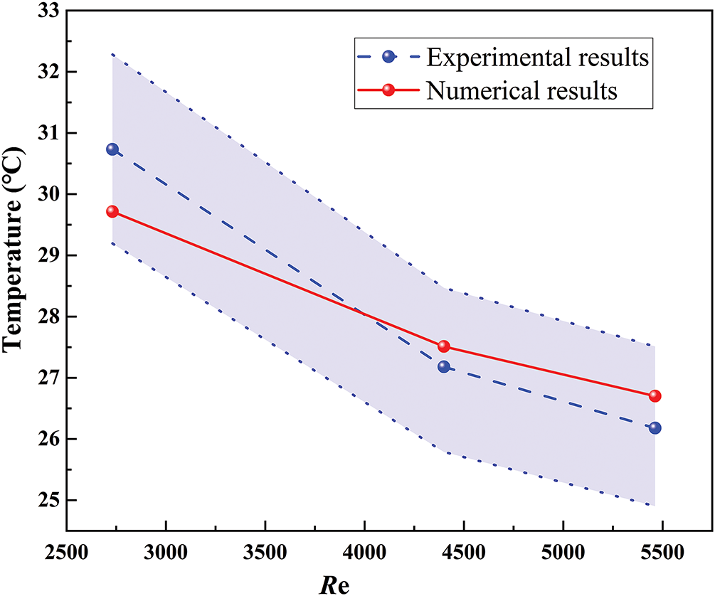
Figure 5: Comparison of simulation results with experimental results
3.1 Electronic Component Heat Dissipation with Natural Convection
Under natural convection conditions, the heat dissipation characteristics of electronic components were studied for a flat fin heat sink at various power levels. The temperature distribution, shown in Fig. 6, indicates that the component temperature is lowest near the air inlet and gradually increases along the airflow direction, maintaining symmetry along the flow path’s centerline. For a 25 W component, the maximum temperature reaches 67.2°C, remaining below the maximum allowable operating temperature of 80°C, ensuring stable performance. However, as the power increases to 50, 75, and 100 W, the maximum temperatures rise to 84.4°C, 97°C, and 103.8°C, respectively, exceeding the allowable operating temperature. Beyond this threshold, the component’s performance deteriorates rapidly, ultimately leading to failure without effective cooling measures.
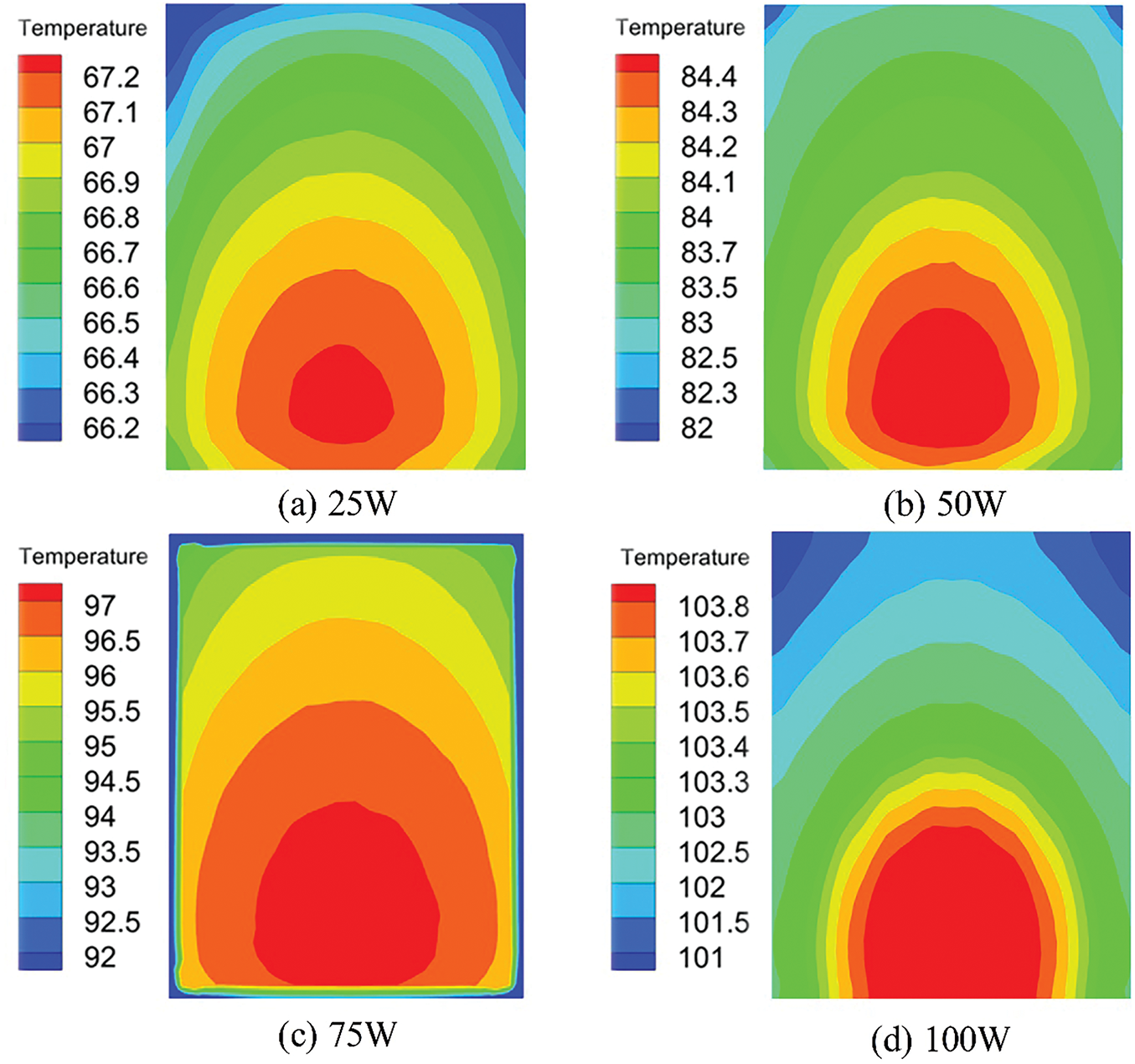
Figure 6: Temperature distribution of electronic components at different power levels under natural convection. (a) 25 W; (b) 50 W; (c) 75 W; (d) 100 W
3.2 The Effect of Incoming Flow Velocity
Fig. 7 illustrates the variation in the maximum temperature of electronic components at different power levels with increasing airflow speed. Under forced convection, the maximum temperature of the components remains below the allowable operating threshold of 80°C, ensuring normal functionality. At a given airflow speed, the maximum temperature rises with increasing power levels of the electronic components.
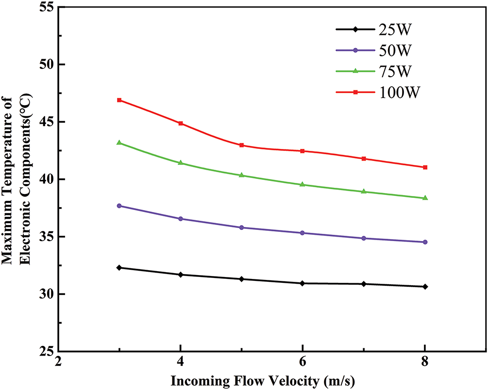
Figure 7: Variation of maximum temperature of electronic components at incoming flow velocity with different power levels
To investigate the heat dissipation mechanism of electronic components under varying airflow speeds, Figs. 8 and 9 illustrate the temperature distributions of a 75 W electronic component and its heat sink at different incoming flow velocities. Both the component and the heat sink exhibit lower temperatures near the air inlet, with temperatures gradually increasing along the airflow direction. At incoming flow velocity ranging from 3 to 8 m/s, the electronic component’s temperature remains between 36.5°C and 42.5°C, significantly below the critical threshold of 80°C, ensuring normal operation. As incoming flow velocity increases, the overall temperatures of the electronic component and heat sink decrease, higher-temperature regions shrink, and temperature uniformity improves. At the same incoming flow velocity, the heat sink’s overall temperature is consistently lower than that of the electronic component, creating a favorable temperature gradient for heat conduction. However, when the incoming flow velocity exceeds 6 m/s, the reduction in higher-temperature regions slows (as shown in Figs. 9d–f).
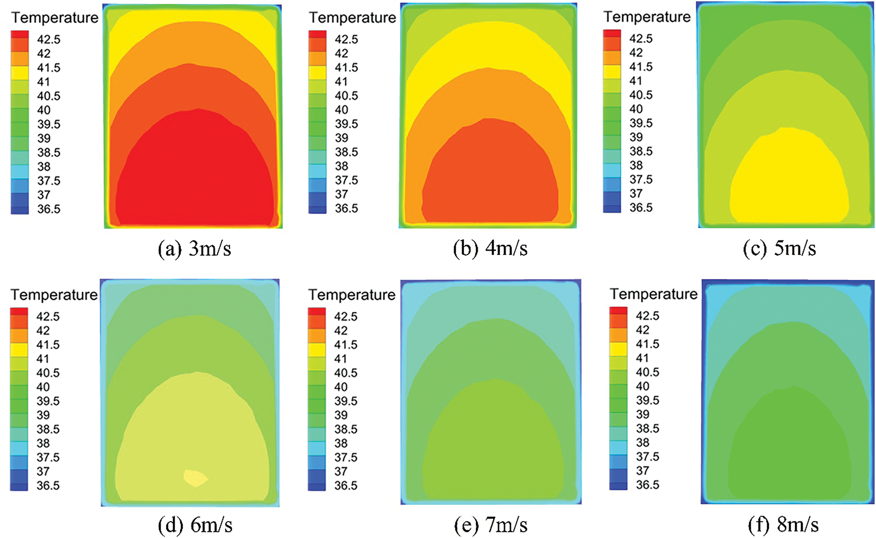
Figure 8: Temperature distribution of a 75 W electronic component at incoming flow velocity of 3 to 8 m/s. (a) 3 m/s; (b) 4 m/s; (c) 5 m/s; (d) 6 m/s; (e) 7 m/s; (f) 8 m/s
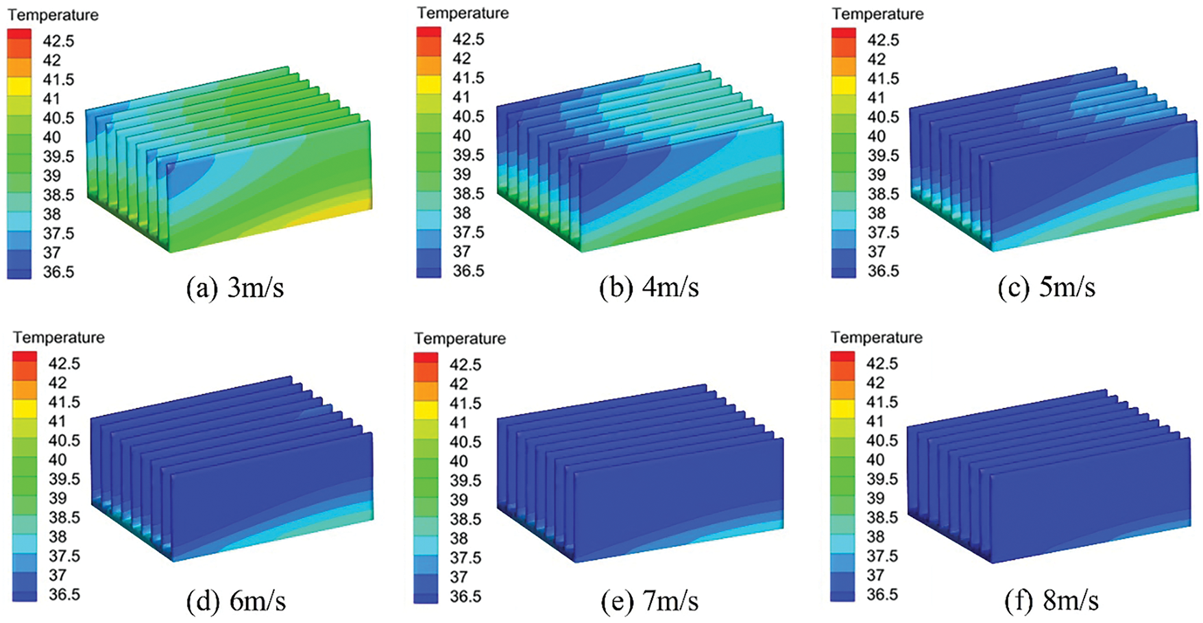
Figure 9: Temperature distribution of the heat sink at incoming flow velocity of 3 to 8 m/s. (a) 3 m/s; (b) 4 m/s; (c) 5 m/s; (d) 6 m/s; (e) 7 m/s; (f) 8 m/s
Fig. 10 shows the pressure distribution cloud map on the Z = 0 mm plane at incoming flow velocity ranging from 3 to 8 m/s. As incoming flow velocity increases, the wake area behind the heat sink expands, and the pressure drop across the heat sink rises. This enhances airflow mixing with the heat sink fins, thereby improving convective heat transfer. However, the increase in incoming flow velocity also generates greater flow resistance, and the work done against this resistance produces heat, warming the heat sink. In addition, the negative pressure values observed in Fig. 10 are indeed caused by local flow recirculation and vortex formation behind the heat sink fins, particularly at higher airflow velocities. When airflow passes through the narrow fin channels and exits the heat sink region, it separates and forms wake regions where the pressure drops below the reference atmospheric pressure, resulting in negative gauge pressure. Although increasing the incoming flow rate can enhance the heat exchange effect, it will also lead to an increase in pressure drop, thereby limiting the practical application effect of certain radiator structures. As a result, when incoming flow velocity exceeds 6 m/s, the expansion of low-temperature regions slows, and further increases in incoming flow velocity yield only marginal improvements in cooling performance. These findings align with the two-dimensional heat dissipation simulation results for electronic components reported by Aglawe et al. [3].
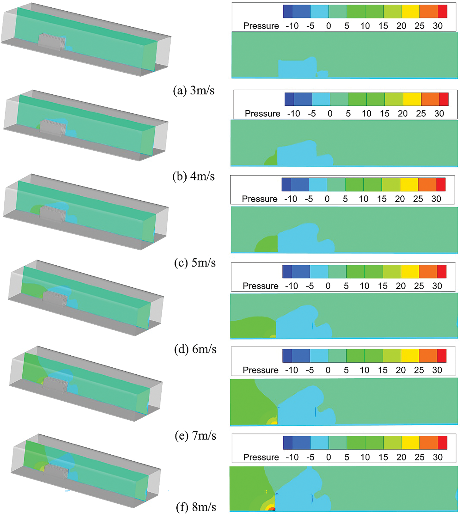
Figure 10: Pressure distribution on the Z = 0 mm plane. (a) 3 m/s; (b) 4 m/s; (c) 5 m/s; (d) 6 m/s; (e) 7 m/s; (f) 8 m/s
Fig. 11 illustrates the relationship between the average heat transfer coefficient, surface means Nusselt number, thermal resistance, and the temperature at a monitoring point on the heat sink surface as incoming flow velocity varies. Both the average heat transfer coefficient and the surface mean Nusselt number increase with incoming flow velocity, though the rate of increase diminishes. Conversely, the temperature at the monitoring point and the thermal resistance of the heat sink decrease with increasing incoming flow velocity, but the rate of decrease also slows. At the same incoming flow velocity, higher electronic component power results in a greater average heat transfer coefficient, surface mean Nusselt number, and monitoring point temperature, while thermal resistance is reduced. This is attributed to the intensified airflow impact at higher incoming flow velocity, which disrupts and thins the thermal boundary layer, enhancing convective heat transfer relative to conductive heat transfer. This increase in convective efficiency elevates the Nusselt number. Simultaneously, the thinning thermal boundary layer reduces the thermal resistance of the heat sink, thereby increasing the average heat transfer coefficient. In Fig. 11d, the knee observed in the 100 W curve at 5 m/s is primarily due to the nonlinear increase in thermal resistance caused by intensified heat generation and flow disturbance at higher power levels. When the electronic component operates at 100 W, the local airflow experiences greater turbulence and potential recirculation near the heat sink surface, especially at moderate incoming flow velocity such as 5 m/s. This leads to a momentary stagnation in the decline of thermal resistance, forming the knee, before enhanced convective heat transfer dominates at higher incoming flow velocities. In contrast, for lower power levels, the flow field remains more stable, and thermal resistance decreases more uniformly with increasing airflow.
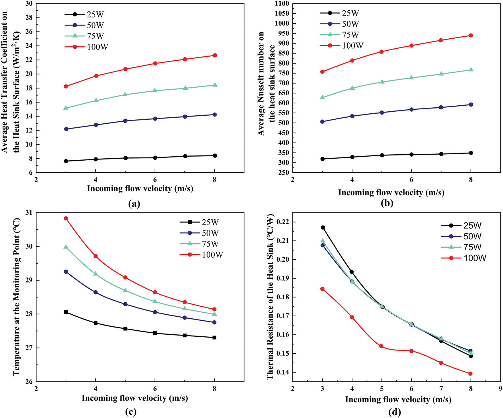
Figure 11: The effect of incoming flow velocity. (a) Variation of the average heat transfer coefficient on the heat sink surface with incoming flow velocity; (b) variation of the average Nusselt number on the heat sink surface with incoming flow velocity; (c) variation of the temperature at the monitoring point with incoming flow velocity; (d) variation of the heat sink thermal resistance with incoming flow velocity
3.3 The Effect of Heat Sink Arrangements
Two flat ribbed heat sinks were arranged in two configurations: parallel on the left and right, and in front and back (as shown in Fig. 12), to analyze their impact on heat dissipation for a 75 W electronic component. The variation in the maximum temperature of the electronic component under natural convection (solid line) and at an incoming flow velocity of 6 m/s (dashed line) is presented in Fig. 13. Under natural convection, the maximum temperature of the electronic component with heat sinks arranged in parallel on the left and right was 76.54°C, compared to 33.55°C at an incoming flow velocity of 6 m/s, a 56.17% reduction. In contrast, when the heat sinks were arranged in front and back, the maximum temperature was 111.26°C under natural convection and 43.39°C at 6 m/s, indicating that this configuration is less effective for heat dissipation under natural convection. The maximum temperature was consistently lower for the parallel left-right arrangement compared to the front-back configuration, under both natural convection and forced convection at 6 m/s. This demonstrates that arranging the heat sinks in parallel on the left and right is more effective for the heat dissipation of electronic components.
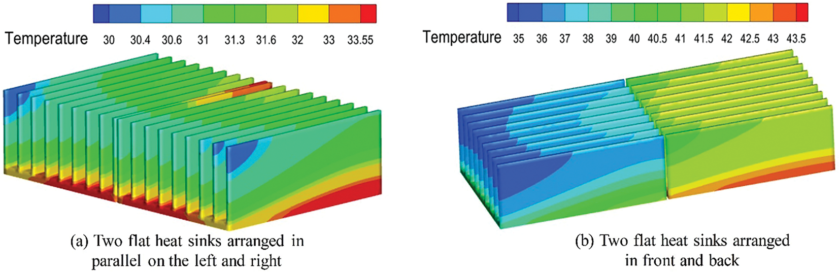
Figure 12: Temperature distribution of the heat sinks with two arrangement methods at an incoming flow velocity of 6 m/s. (a) Two flat heat sinks arranged in parallel on the left and right; (b) Two flat heat sinks arranged in front and back
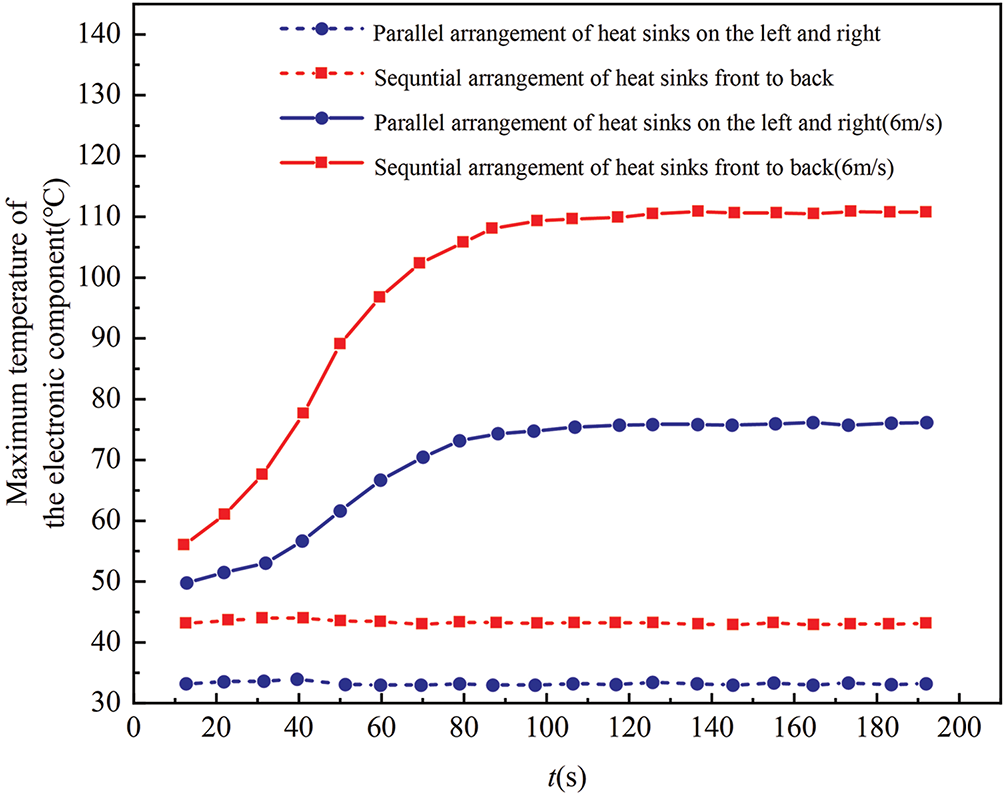
Figure 13: Changes in the maximum temperature of the electronic component with two flat ribbed heat sinks arranged in two different ways under natural convection (solid line) and at an incoming flow velocity of 6 m/s (dashed line)
Figs. 12 and 14 show the temperature distribution of the heat sinks and the velocity distribution on the X = −30 mm plane for both arrangement methods at an incoming flow velocity of 6 m/s. As seen in Fig. 12, the parallel arrangement of the two flat ribbed heat sinks, due to their larger frontal area, results in a smaller temperature difference between the maximum and minimum values, leading to better temperature uniformity. This arrangement also reduces the distance between the end ribs and the casing. When air flows over the heat sink at the same speed, the larger area of the maximum velocity region outside the end ribs and the increased airflow between the ribs extend the effective distance, bringing more air to the ends and interior of the ribs. This enhances convective heat transfer, resulting in stronger heat dissipation compared to the front-to-back arrangement (Fig. 14).
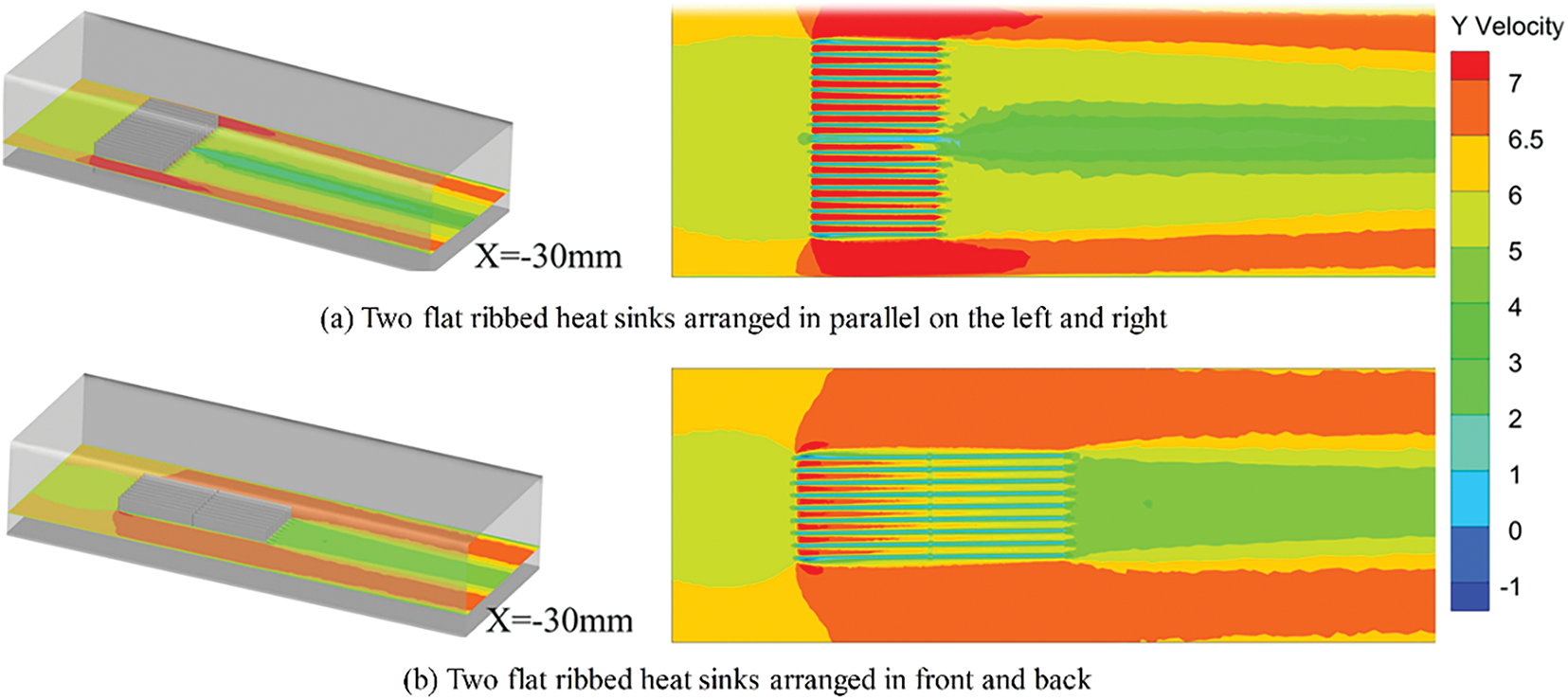
Figure 14: Velocity distribution at X = −30 mm for two arrangement methods at an incoming flow velocity of 6 m/s. (a) Two flat heat sinks arranged in parallel on the left and right; (b) Two flat heat sinks arranged in front and back
3.4 Structure Optimization of Heat Sink
Fig. 15 shows the change in the maximum temperature of a 75 W electronic component cooled by different structured heat sinks under natural convection (solid line) and at an incoming flow velocity of 6 m/s (dashed line). The number of iterations in the horizontal coordinate represents the number of solver iterations within each time step during the steady-state simulation process. Under natural convection, the use of a heat sink with triangular prism-shaped fins and one with semicircular winglets on the fin surface reduced the maximum temperature by 2.15°C and 3.22°C, respectively, corresponding to decreases of 2.34% and 3.35%. At an incoming flow velocity of 6 m/s, the maximum temperatures were 36.5°C and 35.5°C, reflecting reductions of 7.8% and 10.3%. These results demonstrate that the new structured heat sinks significantly lower the maximum temperature of the electronic component, with the cooling effect becoming more pronounced at higher incoming flow velocities.
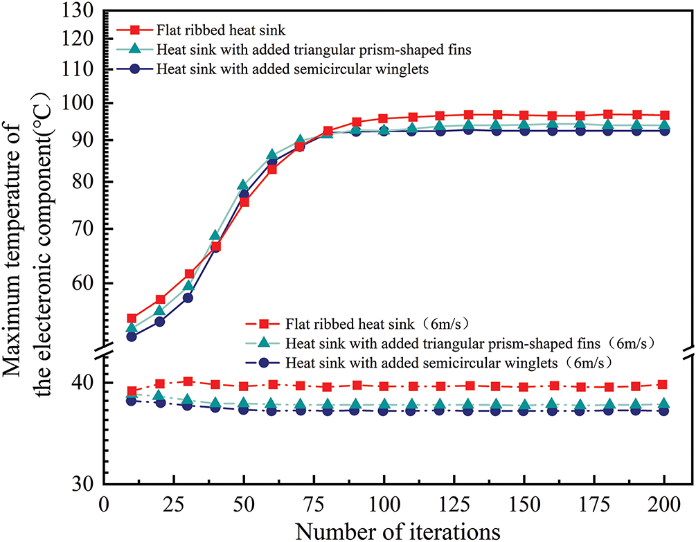
Figure 15: Changes in the maximum temperature of the electronic component with different structured heat sinks under natural convection (solid line) and at an incoming flow velocity of 6 m/s (dashed line)
Fig. 16 shows the temperature distribution of heat sinks with different structures at an incoming flow velocity of 6 m/s. The low-temperature region of the two heat sinks with winglets is significantly larger than that of the flat-ribbed heat sink. Among them, the heat sink with semicircular winglets on the fin surface exhibits an even larger low-temperature area than the one with triangular prism-shaped fins, indicating better temperature uniformity for the winglet-enhanced designs. This indicates that changing the geometry of the winglets can significantly affect the flow separation and recirculation patterns, thereby influencing the overall heat dissipation performance. Furthermore, the maximum temperature of both newly structured heat sinks is lower than that of the flat ribbed heat sink, highlighting the superior heat dissipation performance of these new structures.
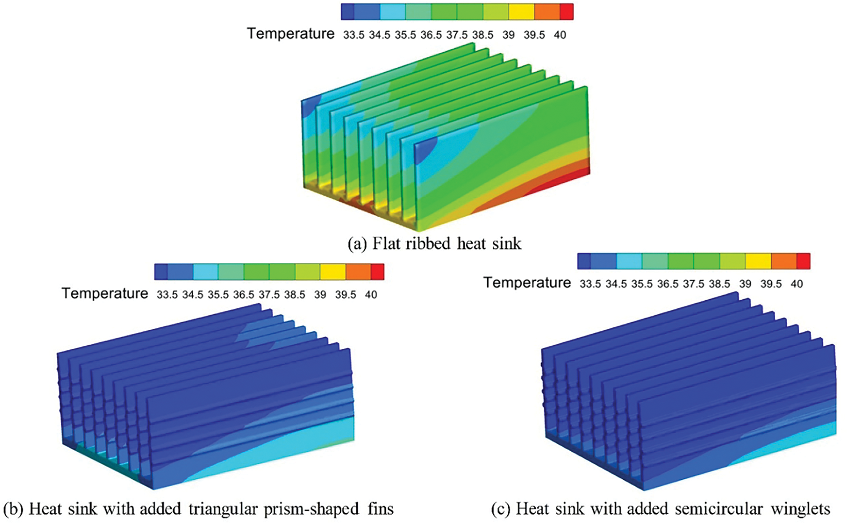
Figure 16: Temperature distribution of heat sinks with different structures at an incoming flow velocity of 6 m/s. (a) Flat ribbed heat sink; (b) Heat sink with added triangular prism-shaped fins; (c) Heat sink with added semicircular winglets
Fig. 17 shows the temperature and velocity distributions of three different heat sink structures on the X = −30 mm plane, demonstrating the superior cooling performance of winglet-enhanced heat sinks. The flow field distributions on various Y planes are presented in Fig. 18. As seen in Fig. 17, both the temperature of the heat sink and the air velocity between the fins increase along the Y direction. This results in higher buoyancy-driven plume velocity, allowing cooler air to flow over the heat sink at higher speeds. The fluid velocity is highest at the outer edges of the fins at both ends of the winglet-equipped heat sinks, and the area of the maximum velocity region is the largest. From the streamline distribution around the radiator shown in Fig. 18, it is found that a backflow phenomenon occurs under high flow velocity conditions. This indicates that although the inlet velocity is relatively high, due to the complex interaction between the airflow and the radiator geometry, including factors such as flow separation and wake formation, a backflow phenomenon may still occur in local areas. Fig. 18a shows the flow field distribution for a flat ribbed heat sink. At Y = −100 mm, a smaller longitudinal vortex forms at the fin ends, which increases in scale and intensity along the Y direction due to the buoyancy-driven plume. This longitudinal vortex induces pulsations that cause airflow fluctuations, increasing turbulence intensity, enhancing airflow mixing, and disturbing the boundary layer. This disturbance transfers more heat to the core flow, improving heat transfer. Compared to flat ribbed (Fig. 17a), the heat sink with triangular prism-shaped fins (Fig. 17b) forms larger, more intense longitudinal vortices earlier in the flow field, which are intermittent and regenerate along the flow direction, enhancing the inlet effect. The heat sink with semicircular winglets (Fig. 17c) produces a larger longitudinal vortex at the Y = −20 mm plane, leading to stronger heat transfer, further validating the temperature distribution from the simulation in Fig. 16.
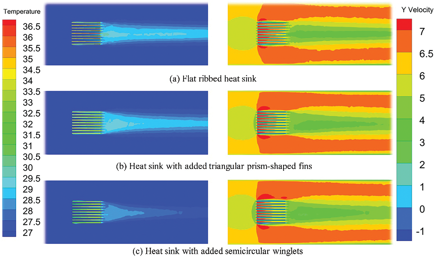
Figure 17: Temperature and velocity distribution of heat sinks with different structures on the X = −30 mm plane at an incoming flow velocity of 6 m/s. (a) Flat ribbed heat sink. (b) Heat sink with added triangular prism-shaped fins (c) Heat sink with added semicircular winglets
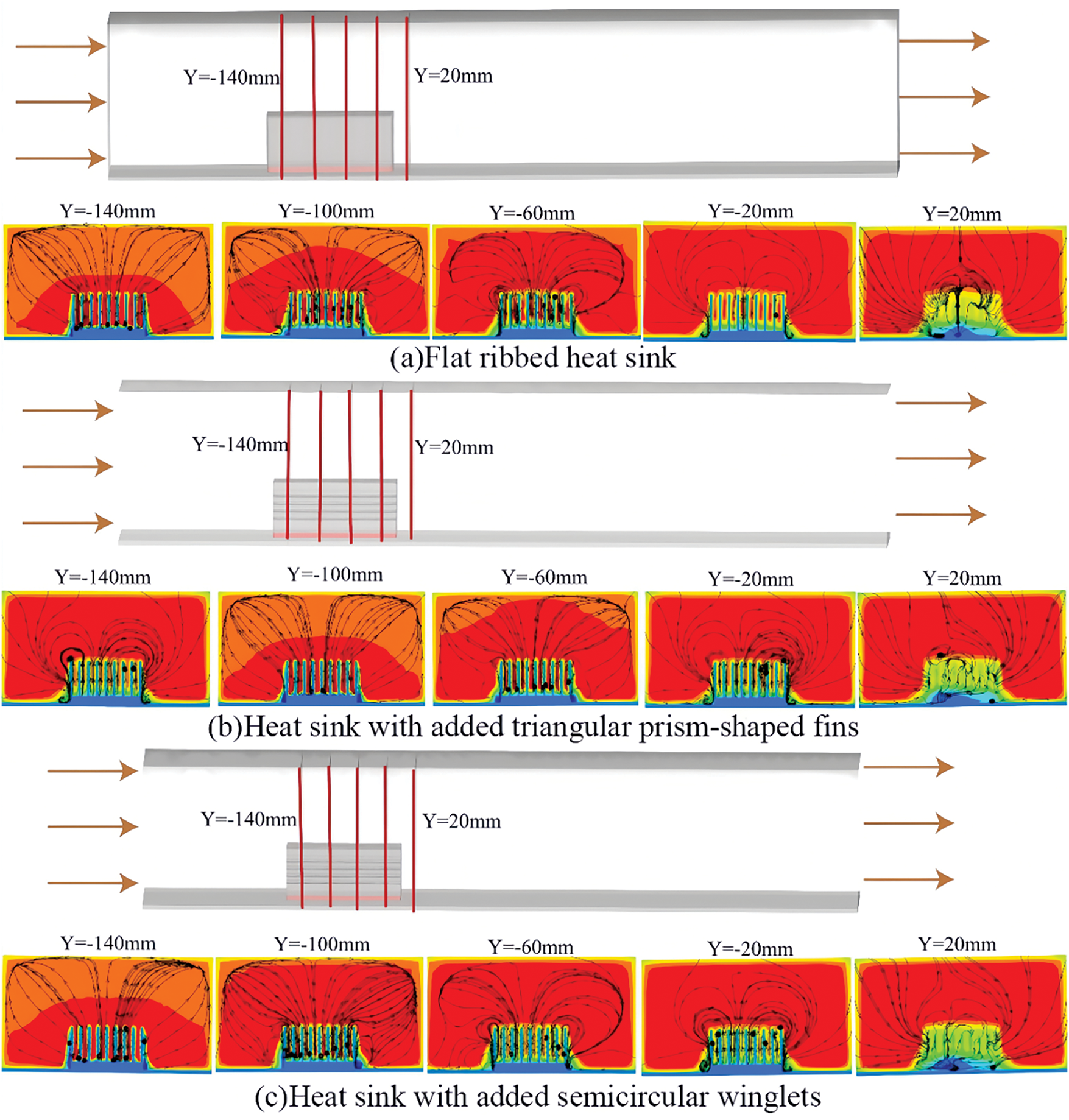
Figure 18: Flow field distribution of heat sinks with different structures on different Y planes at an incoming flow velocity of 6 m/s. (a) Flat ribbed heat sink. (b) Heat sink with added triangular prism-shaped fins. (c) Heat sink with added semicircular winglets
Effective heat dissipation is crucial for the stable operation of electronic components. This paper optimizes heat dissipation by adjusting incoming flow velocity, the arrangement of flat ribbed heat sinks, and heat sink structures. It also analyzes the heat dissipation mechanism under varying incoming flow velocities and compares the cooling effects of different heat sink arrangements and structures. The following conclusions are drawn:
(1) When using a flat ribbed heat sink to cool electronic components of various power levels, increasing the incoming flow velocity enhances the mixing between the air and the heat sink fins. This intensifies the airflow effect, disrupts and thins the temperature boundary layer, reduces thermal resistance, and increases the heat transfer coefficient and Nusselt number, thereby improving convective heat transfer.
(2) In comparison to the front-and-back arrangement of two flat ribbed heat sinks, the parallel arrangement (left and right) results in a lower maximum temperature, better temperature uniformity, and a larger area of maximum velocity regions on the heat sink’s outer fins and between the fins. This configuration extends the effective distance, enhancing convective heat transfer, and making it more effective for cooling electronic components.
(3) Heat sinks with winglets significantly improve cooling performance, with the heat sink featuring semicircular winglets on the fin surface performing best, followed by the heat sink with triangular prism-shaped winglets. Under natural convection, these heat sinks reduce the maximum temperature of the electronic components by 3.35% and 2.34%, respectively. At an incoming flow velocity of 6 m/s, the maximum temperature is reduced by 10.3% and 7.8%, respectively.
In future work, based on this paper, by exploring other complex fin geometries, advanced cooling technologies, and applying optimization algorithms, the heat dissipation efficiency and server reliability will be further improved.
Acknowledgement: The authors would like to acknowledge the constructive remarks by worthy reviewers that led to this revised article.
Funding Statement: This work was supported by the key technology project of China Southern Power Grid Corporation (GZKJXM20240009).
Author Contributions: The authors confirm contribution to the paper as follows: study conception and design: Zerui Chen, Xin Wu, Houpeng Hu; analysis and interpretation of results: Zerui Chen, Xin Wu, Houpeng Hu; draft manuscript preparation: Zerui Chen, Yang Zhou, Shang Yang. All authors reviewed the results and approved the final version of the manuscript.
Availability of Data and Materials: The data that support the findings of this study are available from the corresponding author, Zerui Chen, upon reasonable request.
Ethics Approval: Not applicable.
Conflicts of Interest: The authors declare no conflicts of interest to report regarding the present study.
References
1. Deng Y, Zhang M, Jiang Y, Liu J. Two-stage multichannel liquid-metal cooling system for thermal management of high-heat-flux-density chip array. Energy Convers Manag. 2022;259(7589):115591. doi:10.1016/j.enconman.2022.115591. [Google Scholar] [CrossRef]
2. Chen Z, Feng H, Zhang G, Yang C. Design and implementation of automatic cooling case based on high-power and high-density power supply array. Electronics. 2023;12(20):4353. doi:10.3390/electronics12204353. [Google Scholar] [CrossRef]
3. Aglawe KR, Yadav RK, Thool SB. Fabrication, experimentation and numerical simulation of micro channel heat sink for enhancing thermal performance of electronic devices. Int J Interact Des Manuf Ijidem. 2024;18(5):3217–32. doi:10.1007/s12008-023-01482-7. [Google Scholar] [CrossRef]
4. Zhang X, Ma K, Liu X, Huang W, Liu S, Zhou Y. Optimization of pin fin structure for uniform temperature distribution in multi-chip parallel-connected power modules. In: 2024 25th International Conference on Electronic Packaging Technology (ICEPT); 2024 Aug 7–9; Tianjin, China. doi:10.1109/ICEPT63120.2024.10668518. [Google Scholar] [CrossRef]
5. Lakshminarayanan V, Sriraam N. The effect of temperature on the reliability of electronic components. In: 2014 IEEE International Conference on Electronics, Computing and Communication Technologies (CONECCT); 2014 Jan 6–7; Bangalore, India. doi:10.1109/CONECCT.2014.6740182. [Google Scholar] [CrossRef]
6. Otiaba KC, Ekere NN, Bhatti RS, Mallik S, Alam MO, Amalu EH. Thermal interface materials for automotive electronic control unit: trends, technology and R&D challenges. Microelectron Reliab. 2011;51(12):2031–43. doi:10.1016/j.microrel.2011.05.001. [Google Scholar] [CrossRef]
7. Wang Q, Tao J, Cui Z, Zhang T, Chen G. Passive enhanced heat transfer, hotspot management and temperature uniformity enhancement of electronic devices by micro heat sinks: a review. Int J Heat Fluid Flow. 2024;107(4):109368. doi:10.1016/j.ijheatfluidflow.2024.109368. [Google Scholar] [CrossRef]
8. Huang CH, Wang GJ. A design problem to estimate the optimal fin shape of LED lighting heat sinks. Int J Heat Mass Transf. 2017;106:1205–17. doi:10.1016/j.ijheatmasstransfer.2016.10.101. [Google Scholar] [CrossRef]
9. Abdulsahib AD, Alkhafaji D, Albayati IM. Optimizing heat sink performance by replacing fins from solid to porous inside various enclosures filled with a hybrid nanofluid. Front Heat Mass Transf. 2024;22(6):1777–804. doi:10.32604/fhmt.2024.057209. [Google Scholar] [CrossRef]
10. Choi H, Lee H, Kim J, Lee H. Hybrid single-phase immersion cooling structure for battery thermal management under fast-charging conditions. Energy Convers Manag. 2023;287(9):117053. doi:10.1016/j.enconman.2023.117053. [Google Scholar] [CrossRef]
11. Zhang Z, Wang X, Yan Y. A review of the state-of-the-art in electronic cooling. e-Prime—Adv Electr Eng Electron Energy. 2021;1(1):100009. doi:10.1016/j.prime.2021.100009. [Google Scholar] [CrossRef]
12. Tari I, Mehrtash M. Natural convection heat transfer from inclined plate-fin heat sinks. Int J Heat Mass Transf. 2013;56(1–2):574–93. doi:10.1016/j.ijheatmasstransfer.2012.08.050. [Google Scholar] [CrossRef]
13. Ke H, Lin Y, Ke Z, Xiao Q, Wei Z, Chen K, et al. Analysis exploring the uniformity of flow distribution in multi-channels for the application of printed circuit heat exchangers. Symmetry. 2020;12(2):314. doi:10.3390/sym12020314. [Google Scholar] [CrossRef]
14. Muneeshwaran M, Tsai MK, Wang CC. Heat transfer augmentation of natural convection heat sink through notched fin design. Int Commun Heat Mass Transf. 2023;142(4):106676. doi:10.1016/j.icheatmasstransfer.2023.106676. [Google Scholar] [CrossRef]
15. Huang CH, Chen L. An optimized natural convection Y-shape-shifted heat sink design problem. Case Stud Therm Eng. 2021;28(1):101520. doi:10.1016/j.csite.2021.101520. [Google Scholar] [CrossRef]
16. Abbas A, Wang CC. Augmentation of natural convection heat sink via using displacement design. Int J Heat Mass Transf. 2020;154(1):119757. doi:10.1016/j.ijheatmasstransfer.2020.119757. [Google Scholar] [CrossRef]
17. Ahmadi M, Mostafavi G, Bahrami M. Natural convection from rectangular interrupted fins. Int J Therm Sci. 2014;82(2):62–71. doi:10.1016/j.ijthermalsci.2014.03.016. [Google Scholar] [CrossRef]
18. Mousavi H, Ali Rabienataj Darzi A, Farhadi M, Omidi M. A novel heat sink design with interrupted, staggered and capped fins. Int J Therm Sci. 2018;127:312–20. doi:10.1016/j.ijthermalsci.2018.02.003. [Google Scholar] [CrossRef]
19. Gurav RB, Purohit P, Tamkhade PK, Nalavade SP. Computational and analytical study on CPU heat sink cooling by single and double stack air-foil micro pin fins. Mater Today Proc. 2023;92(Part 1):6–10. doi:10.1016/j.matpr.2023.03.130. [Google Scholar] [CrossRef]
20. Naphon P, Klangchart S, Wongwises S. Numerical investigation on the heat transfer and flow in the mini-fin heat sink for CPU. Int Commun Heat Mass Transf. 2009;36(8):834–40. doi:10.1016/j.icheatmasstransfer.2009.06.010. [Google Scholar] [CrossRef]
21. Khudhur DS, Al-Zuhairy RC, Kassim MS. Thermal analysis of heat transfer with different fin geometry through straight plate-fin heat sinks. Int J Therm Sci. 2022;174(6S):107443. doi:10.1016/j.ijthermalsci.2021.107443. [Google Scholar] [CrossRef]
22. Li HY, Wu YX. Heat transfer characteristics of pin-fin heat sinks cooled by dual piezoelectric fans. Int J Therm Sci. 2016;110:26–35. doi:10.1016/j.ijthermalsci.2016.06.030. [Google Scholar] [CrossRef]
23. Sufian SF, Abdullah MZ. Heat transfer enhancement of LEDs with a combination of piezoelectric fans and a heat sink. Microelectron Reliab. 2017;68(14–15):39–50. doi:10.1016/j.microrel.2016.11.011. [Google Scholar] [CrossRef]
24. Shan X, Liu B, Zhu Z, Bennacer R, Wang R, Theodorakis PE. Analysis of the heat transfer in electronic radiator filled with metal foam. Energies. 2023;16(10):4224. doi:10.3390/en16104224. [Google Scholar] [CrossRef]
25. Nair V, Baby A, Anoop MB, Indrajith S, Murali M, Nair MB. A comprehensive review of air-cooled heat sinks for thermal management of electronic devices. Int Commun Heat Mass Transf. 2024;159:108055. doi:10.1016/j.icheatmasstransfer.2024.108055. [Google Scholar] [CrossRef]
26. Hussein MA, Hameed VM, Dhaiban HT. An implementation study on a heat sink with different fin configurations under natural convective conditions. Case Stud Therm Eng. 2022;30(4):101774. doi:10.1016/j.csite.2022.101774. [Google Scholar] [CrossRef]
27. Yu C, Zhu X, Li Z, Ma Y, Yang M, Zhang H. Optimization of elliptical pin-fin microchannel heat sink based on artificial neural network. Int J Heat Mass Transf. 2023;205(5–6):123928. doi:10.1016/j.ijheatmasstransfer.2023.123928. [Google Scholar] [CrossRef]
28. Mohit MK, Gupta R. Numerical investigation of the performance of rectangular micro-channel equipped with micro-pin-fin. Case Stud Therm Eng. 2022;32:101884. doi:10.1016/j.csite.2022.101884. [Google Scholar] [CrossRef]
29. Kanargi OB, Lee PS, Yap C. A numerical and experimental investigation of heat transfer and fluid flow characteristics of a cross-connected alternating converging-diverging channel heat sink. Int J Heat Mass Transf. 2017;106:449–64. doi:10.1016/j.ijheatmasstransfer.2016.08.057. [Google Scholar] [CrossRef]
Cite This Article
 Copyright © 2025 The Author(s). Published by Tech Science Press.
This work is licensed under a Creative Commons Attribution 4.0 International License , which permits unrestricted use, distribution, and reproduction in any medium, provided the original work is properly cited.
 Downloads
 Citation Tools