
 Submit a Paper
 Propose a Special lssue
 Open Access
ARTICLE
Improving the Performance of Thermoelectric Systems for Air Conditioning Using Different Configurations
Electromechanical Engineering Department, University of Technology, Baghdad, 0096, Iraq
* Corresponding Author: Ameer Abed Jaddoa. Email:
Frontiers in Heat and Mass Transfer 2025, 23(4), 1281-1302. https://doi.org/10.32604/fhmt.2025.066075
Received 28 March 2025; Accepted 27 May 2025; Issue published 29 August 2025
 View Full Text
 Download PDF
Abstract
Thermoelectric air conditioning systems based on the Peltier effect had two modes: heating and cooling. In this work, the proposed design provides continuous improvement in COP from the first minute of operation. In cooling mode, the coefficient of performance (COP) was 1.176 due to the techniques used in this device, and it increased to 1.24 in the last minute of operation. Concerning the steady-state scenario, from the first minute, the Qc was larger than the W for the entire duration of the operation. The output temperature reaches 18.97°C, and the temperature on the cold side reaches 4.96°C in the fifteen minutes of operation. The cooling mood was checked in Iraq/Baghdad in October with a temperature of 31°C. Furthermore, the heating mode was checked in December with a temperature of 22°C. Due to the size of the component on the cold side being small compared with the size of the component on the heat side, it reached a steady state in 13 min. This means the COP in heating mode reached 1.01 in 14 min. Furthermore, due to the presence of a thermal insulator made inside the device to separate the cold side and the hot side, the difference in temperature causes a noticeable little ascent. This is why the COP increased because it kept the degree differences low. Performance enhancements were achieved by optimizing the behavior of thermoelectric materials. The device contains 3 Peltier elements, a water-cooled system with one Peltier, a heat sink, and a fan. The design of the dehumidification system addresses the humidity issue commonly associated with thermoelectric air conditioners. In this context, the results indicate that the humidity rates had decreased and the cooling rate had increased with these innovative techniques, and thus, excellent performance can be achieved even if the Seebeck coefficient is not at its highest based on the condition of providing the Peltier elements’ reliability and optimal thermal performance for various applications requiring both cooling and heating functions. The insulation plays a critical role in maintaining the efficiency of the system, reducing energy consumption, and ensuring long-term functionality. The proposed system is valuable for devices or environments that demand precise and dual thermal control with minimal energy wastage.Keywords
Thermoelectric devices do not have any moving parts, are eco-friendly, have a wide operating temperature range, have no chemical reaction, are maintenance-free, have a long life span, and have low power consumption [1,2]. The efficiency of thermoelectric cooling systems can become comparable to that of traditional systems by improving the thermal properties utilized, which demonstrates their great potential for energy savings in buildings and ensures thermal comfort conditions [3,4]. Energy-saving research about environmental alternatives for use in air conditioning systems has become the first of global priorities [5]. In thermoelectric materials, electrical energy is converted directly into thermal energy. The direct conversion between electrical and thermal energy occurs due to the effects of the Seebeck effect and the Peltier effect, and the Peltier effect indicates the absorption of heat at one of the materials due to the Peltier effect and the release of heat from the opposite side due to the flow of current through the material. In addition, its advantage is that it can be powered by direct current; a voltage or DC is applied to two dissimilar conductors, and a circuit can be created that allows for continuous heat transport between the conductors’ junctions. This is the principle of thermoelectric air conditioning [6]. Thermoelectric materials consist of pairs of n-type and p-type [7]. Electrical thermal units (Peltier) can be an effective alternative to traditional air conditioning if developed, especially in applications that require energy saving. In general, calculated COP values are low. The COP of vapor compression systems seems to be higher than that of TE by considering working conditions [8]. In some cases, when the temperature of the outside air is close to the air temperature of the internal unit, a COP change in operating conditions can lead to a decrease in the performance coefficient. Thermal effectiveness is lower, which leads to a decrease in the system’s ability to cool or heat, and therefore it will need to consume more energy to achieve the desired temperature, which leads to increasing operational costs and reduced efficiency [9]. The COP of the TE system increases with increasing current up to a certain value, and then it further decreases. The COP decreases with an increase in input power and temperature difference. The Peltier connection circuit performs best when configured in parallel, requiring a fixed current and voltage, which translates to low voltage and high current; this configuration aligns with previous energy needs and the growing awareness of renewable energy [10]. The use of fossil fuels was to provide energy needs in various places all over the world and had a significant impact on the upward trend in the consumption of energy and gas emissions. Fossil fuels are the main source in some industries. The importance of improving fossil fuel combustion efficiency has been highlighted to achieve fuel consumption and improve thermal efficiency. One of the proposed methods is technology, modeling, and thermodynamic simulation to improve heating and CFD analysis [11,12]. The higher COP, which was based on a parallel connection and an angle position of 90°, proved that the parallel connection is better than the series connection and the position angle of 90° for Peltier in the box (placed vertically). At the position angle of 90° and when the current was increasing, the COP increased [13]. And increasing ambient temperature reduces [14]. Thermoelectric materials are developed to achieve effective cooling and can be used in various applications, such as cooling devices to achieve the thermal comfort of people during movement in the semi-open transitional spaces of gates and corridors [15,16]. Air conditioning systems provide thermal comfort, reduce energy consumption, achieve remarkable improvements, save energy greatly, and reduce long-term operation costs. They are used in homes and offices [17,18]. Air conditioning work in Peltier systems is used as an economical solution to cooling and can be used in home offices and vehicles, as it is characterized by high thermal efficiency and low energy consumption [19,20]. In this current study, the experimental work consists of sophisticated, innovative air conditioning with a thermoelectric unit based on the Peltier effect with innovative thermal insulation, different techniques, and integrated dehumidification. The device is made of an aluminum cover. The device is designed with a double-effect system for cooling and heating, working with a movable cover that has the cold and hot junctions separated by insulation made with more than one layer of NBR material for the hot side and aluminum for the cold side. The air conditioning device contains 3 Peltier-type TEC1-12703s (Model: TEC1-12703; Voltage (V): 12 V; Max Current (A): 3 A; Resistance: 4.0–4.3 Ω; Dimensions: 40 mm × 40 mm × 4.2 mm Thermoelectric Cooler), an air system, a water-cooled system with one Peltier-type TEC1-12703, a heat sink and fan, and a novelty integrated dehumidification system without a compressor. There are three inlet slots in a circle shape and the outlet; the circular shape enhances smooth air entry.
Research [21] develops a solar thermoelectric refrigerator (STER) by using a thermoelectric module based on the Peltier effect. The experimental model considers a steel-aluminum box of dimensions (200 × 195 × 300) mm3. Inside the STER, two thermoelectric (TE) modules of type TEC-12703 were placed on the back side of the STER prototype, and two heat sinks with two cooling fans. The cold side of the TEM for refrigeration used inside the refrigerator rejected heat from the other hot side of the module to the ambient surroundings through heat sinks and fans. Each heat sink is used to improve heat dissipation from the hot side of the TEM, and on each side of the modules, two cooling fans are used in the prototype. These fans are used to cool internal fins and reject additional heat from ambient surroundings. In the STER prototype, the TEC1-12706 thermoelectric module is wedged between the two heat sinks. A temperature sensor is a device that measures the inside cabin temperature and outside hot heat sink temperature directly in contact with the physical object. The experimental result indicates that the STER unit reduces room temperature from 33°C to 4.1°C in 44 min with a coefficient of performance (COP) of 0.61. The technique used is two heat sinks with two cooling fans. Each module’s heat sink is used to improve heat dissipation from the hot side of thermoelectric modules; fans are used to cool internal fins, and additional heat is rejected for ambient surroundings. The TEC1-12706 thermoelectric Peltier module is wedged between the two heat sinks.
In this research [22], the investigation is experimental and theoretical about the performance of a cooling system that works technically on a thermoelectric system depending on the Peltier effect, a thermoelectric air-conditioning system (TEACS) driven by photovoltaics (PV). The PV panels produce electricity, which is utilized to drive the TEACS directly and to charge batteries that store power to be exploited during nighttime. The experiments were conducted in Sohag, Egypt, within an average 1 m3 confined space; the room was made with wood and insulated with foam. Use sixteen thermoelectric modules of the Peltier TEC1-12706 type as thermoelectric devices placed in the air duct. Twelve lamps are installed to get net thermal loads inside the conditioning room from W to W, and the halogen lamps’ voltage is controlled by changing the thermal load. The system is powered by a PV panel. and techniques used Six rectangular fin heat sinks made of aluminium are attached to the hot and cold sides of the TEMs to heat or cool the air more efficiently and Thermal grease sandwiched between the TEM and the heat sink is used to minimize thermal contact resistances. Condenser and evaporator fans, as well as two variable-speed centrifugal blowers, are used at the hot and cold sides (at the inlet of each air duct).
In this study [23], an experimental and numerical approach is used to evaluate the thermoelectric refrigerator. A refrigerator is designed for the experimental study with an inner volume of 05 m3 (50 L), and the refrigerator operates by DC power supply. The efficiency of the system is investigated through the performance coefficient; the maximum coefficient of performance registered is 0.73 to 0.1. This means the TEC’s lower-cooling behaviour at temperature differences between the cold and hot surfaces of the Peltier module has led to a gradual decrease in the associated coefficient of performance (COP). The experimental results confirm that during the time interval (0–20) min, the temperature inside the thermoelectric refrigerator has decreased at a rate of 1.5°C/min. For inner and external configuration, the inner configuration is made to cool the water in the water tank, and the external one is made to cool the refrigerator. The TE refrigerator and cooling water circulate in two aluminium water blocks via pump. A cold-water circulation system was used to cool the surfaces of the modules inside the refrigerator. In order to keep the cold water at the same temperature (always between 13°C and 15°C) during the measurement, the technique that was used is water and air that is used to dissipate the hot air coming from the Peltier module and the inner and external configuration of the water-cooler block, with Peltier, fans, heat sinks, and the high thermal conductivity of thermal paste used to eliminate the thermal contact resistance effect in each junction of the TEC.
TE cooler box for food storage proposed a thermoelectric (TE) cooler box that adopts both conduction and convection heat transfer to solve the problems [24]. The cooler box is made of a three-layer wall and six TE modules (TEC1-12706). The size of the inner cooler box is 610 mm × 504 mm × 372 mm, while the outer cooler box is 696 mm × 590 mm × 458 mm. Results showed steady temperature distributions with time at various points of the layers, including the cold and hot regions. The COP trend at 0.04 above is stable; the COP increases sharply before actualizing stability with experimental time. The techniques used are six inner heatsinks with fans, six outer heatsinks with fans, six top fans, two power supplies, a contactor, a switch, a thermostat, and a TE cooler. It is made of a three-layer wall, six thermoelectric modules, six inner sinks with fans, six outer sinks with fans, six top fans, two power supplies, a contactor, a switch, and a thermostat. The cooler box’s first layer of thickness 3 mm is polypropylene (PP) plastic, the second layer of thickness 80 mm is expanded polypropylene (EPP) foam, and the third layer of thickness 3 mm is aluminum.
This study investigates the impact of a thermoelectric subcooler (TESC) on the performance of a vapor compression refrigeration system employing R134a as the working fluid [25]. The experimental setup comprises a compressor, condenser, expansion valve, evaporator, and a thermoelectric subcooler, with the system powered by a direct current (DC) power supply. The TESC, incorporating a TEC1-12706 thermoelectric module, was designed, fabricated, and installed at the outlet of the condenser. The subcooling temperature range achieved was between 273 and 281 K. The thermoelectric module (TEM) acted as a subcooling unit at the condenser outlet and was experimentally evaluated for its influence on system performance. The results demonstrated that the application of the TESC enhanced the cooling capacity while reducing the coefficient of performance (COP) of the TESC unit itself. However, the overall system performance improved significantly; specifically, the COP of the refrigeration system increased by 27.31%, and the cooling capacity was enhanced by 50.72% at a subcooling temperature of 281 K. The thermal management strategy employed in the design included an aluminum heat sink affixed to the hot side of the thermoelectric modules, and a copper tube integrated into the cold side to facilitate refrigerant flow. Additionally, four custom-fabricated aluminum blocks were used to secure the components and improve thermal transfer to the copper tube. High thermal conductivity thermal grease was applied to ensure effective heat transfer between surfaces. An axial fan was utilized to dissipate heat from the aluminum heat sink, thereby maintaining an adequate temperature gradient across the TEM required for efficient subcooling operation.
This part shows the device is equipped with cooling and heating, as shown in Fig. 1. It works with this technology. The system design shown in Figs. 2 and 3 had a movable cover made with aluminum because it is characterized by high thermal conductivity, which makes it able to transfer heat efficiently, and the ability of aluminium to transfer warmth. This feature makes aluminium a favorite material in cooling systems and when used in this type of air conditioning system because it can get rid of heat quickly or distribute it evenly due to its high conductivity of aluminium [26]. The hot side of the air conditioning device had a larger heat sink and larger fan. The larger fan on the hot side was connected with control speed to get rid of more quickly away from the Peltier component, positioning the Peltier component inside the device shown in Fig. 4 and the component shown in Fig. 5. This air was disposed of by a DC brushless fan that was placed on the roof of the device cover (placed in a way that draws away to outside the device). The experimental technical protocol procedure has been determined; the development of this technology and exploitation of the two parts were carried out to design this device for cooling and heating moods. The hot and cold sides are separated by an insulator made of about 95% aluminium, which helps spread heat evenly, and there are multiple layers of NBR (Nitrile Butadiene Rubber) on the hot side to stop heat from moving to the cold side. This setup helps keep the two sides from getting too hot and reduces heat transfer. It contains holes to circulate the air to the cold and hot sides, and the holes are distributed accurately and evenly, allowing only air to circulate within the device, which prevents the gathering of hot air near the cold part. The cold part remains at a low temperature to increase the life of the Peltier prevent it from damage and reduce the convection. The entry, recycling, and exiting of the air were also studied to obtain the highest possible values for heating and cooling modes without wasting energy. The hot part temperature was decreased upon the startup of the operation. This is due to the two systems that are designed for dissipating heat (the two systems are the water-cooling system and the air system represented by fans). Air in the hot side (cooling mode) is drawn out through a DC brushless fan put in reverse on the roof and draws the hot air outside the device. In heat mode, the system draws in cold air to reduce the load on the Peltier unit, which then flows throughout the room via an aluminium duct and is assisted by connected fans. This fan is connected to a speed controller to control the fan speed. The work of the fan on the cold side of this device is recycling the cold air in the cold area. This means the air inside the two parts is trying to reach the cooling by the fans. This resulted in a close temperature on both sides. the temperature closeness resulted in increased cooling efficiency, compared to other devices, especially the high COP, which indicates heat discharge and saves the cold air and reverses the operation in the heat-indicated cold air discharge and saving the hot air this duo to the movable cover device and unwanted air flows through the out the room, the COP rose immediately and high stable because of the fixed voltage, fixed current because this is why because of the insulation piece leads placed in the middle between the two parts placed to maintaining difference temperature between the hot and cold sides few and close throughout the operation period, the system has been powered by power supply to get fixed voltage and high power to prevent the Peltier from damage. This work has been experimental in Baghdad in October for the cooling mood and the heating mood in December consists of three thermoelectric modules of type TEC1-12703. The thermoelectric Peltier module is sandwiched between the two heat sinks and is clamped and glued by thermal grease HY710 and thermal conductivity. Greater than 3.17 W/m·k, ensure the effective heat dissipation of electronic components. Each of these TEC units has two fans, two heat sinks, and one water cooler. The water cooler for the heat side is connected with a water submersible pump that is placed in a water tank made with aluminium, and one Peltier is placed on the side of the water tank, water tank is shown in Fig. 6. It is close to the surface of the aluminium tank for cooling water, and the side of this Peltier heat sink and fan distracts the heat that comes from the hot side of the Peltier. A submersible pump is placed inside the water tank; it pumps the water from the water-cooling block to the aluminium radiator by tubes then the water flows into the sumps of the water tank by gravity. It is combined with two systems of water and air, and each system works in two stages. All the TEC modules are connected to a 12-V DC power supply module in parallel connection, and Table 1 shows the equipment and its specifications. The cover is rotated according to the user’s desire, and the flow hole (outlet slot) is according to the case wanted. Wanted air is pumped through the outlet slot, and the other is to get rid of it by the roof fan and disposed of by duct out of the room. The device has dehumidification systems that are shown in Fig. 7, which consist of copper tubes designed to remove moisture. Dehumidifiers are developed using copper pipes due to the excellent copper properties in heat transfer and corrosion resistance. Removed Wet air through cooled copper tubes, which leads to the moisture intensification on the surface of the pipes and their removal from the air [27,28], the copper tubes are used to drain the condensed water resulting from cooling process, the moisture is withdrawn from the cooling process, the moisture is withdrawn from the air after the cooling process, then it condenses on the cold surface and it drained through these pipes and out of the device to aluminum tank for keeping this process of conduction to make the floor of the air conditioning device by wrapping the plate of the device with aluminum and connected to the aluminum tank that placed below, where the copper tubes extend from the device to the water collection tank resulting from the dehumidification process thus made without any leakage due to the successful occurrence of the operation. Condensed water from the device is done by piercing the plate of work to remove the moisture by dripping water by condensation, and it has been dented and inclined to ensure that the drainage process, when reducing humidity, increases cooling efficiency [29]. Appropriate wires help with the passage of approximately the maximum permissible current to each Peltier in the device. The temperature reading by the controller of temperature consists of twelve pieces of MAX6675 thermocouple K-type and Arduino Mega 2560 R3, https://www.amazon.com/uxcell-TEC1-12703-Thermoelectric-Cooling-Peltier/dp/B07MV24CSZ (accessed on 20 April 2025).
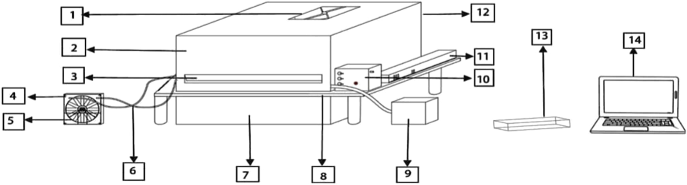
Figure 1: Air conditioning device working with TEC1-12703 module with insulation and different techniques. (1) Roof fan; (2) Aluminium cover device; (3) Outlet slot; (4) Radiator; (5) Fan; (6) Water pipes; (7) Condensation water collection water; (8) A wooden plate wrapped in aluminium; (9) Water tank; (10) ON/OFF switch controller; (11) DC power supply; (12) Inlet slots (the back of the device made with a circular shape); (13) The plastic box consists of an Arduino Mega R3 and 12 pieces of thermocouple MAX6675 (K-type); (14) Computer for display measurement of temperature

Figure 2: Schematic of thermoelectric cooling and heating device with all equipment

Figure 3: Air conditioning device working with TEC1-12703 module

Figure 4: Inside the air conditioning device

Figure 5: Peltier component

Figure 6: Water cooling tank
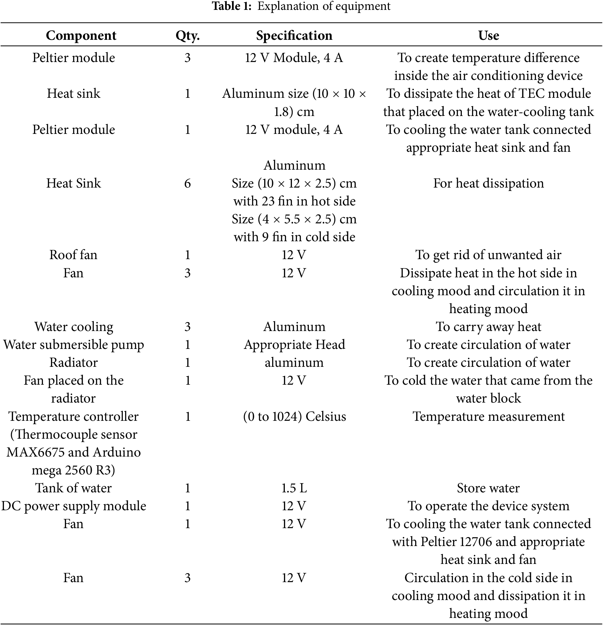

Figure 7: Device from inside showing copper tubes
Air conditioning works with three Peltier module type TEC1-12703. They are placed with their components placed vertically. The components consist sequentially, in order of which the device was operated, of a small fan on the cold side for recycling the cold air and a small heat sink made with aluminium to assist in improving the cooling efficiency, as it distributes the heat from the cooling process, the component of Peltier shown in Fig. 5. The Peltier module TEC1-12703 is clamped and glued with thermal grease HY710, and a radiator made from aluminium is connected with water cooling (block water made with aluminium inside silver metal). A water-cooling system was chosen because the water has a high-quality heat capacity [30,31]. This means it can absorb heat before its temperature rises significantly, and because it has a relatively high density compared to air and a high specific heat capacity compared with air, it can transfer a larger amount of heat of the same size, which makes it an excellent option for cooling applications that require a high heat capacity. It assists in the process of heat dissipation by increasing the surface area, which enhances heat exchange and contributes to the removal of hot air. The water drags the heat from the TEC module in two stages. The first stage involves water cooling and fans, where the heat is dissipated by the radiator and its fan, which is connected to pipes through the water block to enhance the TEC’s ability to cool the cold side more effectively. The second stage is the cooling tank that is cooled by the one piece of Peltier type TEC1-12703 as the second stage for cooling the water that came from the water block. Dissipate heat resulting from the heat transfer process through the module; the dig fan distributes the heat collected on the hot side at the maximum speed, as there is a speed controller that helps up the process, and it allows the transfer of heat more efficiently to the surrounding air, contributing to accelerating the heat dissipation process from the heat sink. Using two heat sinks (for each Peltier), one on the cold side and the other on the hot side, increases cooling capacity with increasing air speed [32]. The aim of these dissipation systems is keeping the hot side as low as possible so that the Peltier module can work effectively in cooling the cold side.
3 Equations and Mathematical Expressions
When using thermoelectricity for air conditioning, several important factors are taken into account, such as the system’s cooling power (Qc), heating power (Qh), the work done by the Peltier module (W), the coefficient of performance (COP), ZT (Thermoelectric figure of merit), and △T (temperature difference). The Seebeck effect coefficient (α), electrical resistivity (R), and thermal conductivity (K) are defined as [33], respectively. The Seebeck effect coefficient (α), electrical resistivity (R), and thermal conductivity (K) are expressed as [33], respectively.
where V is the thermoelectric module voltage of the thermoelectric module, it is the difference in the junction’s temperature of the thermoelectric module. The electrical resistance is expressed as Eq. (2).
The thermal conductivity is expressed as Eq. (3).
where △T = Th − Tc is the difference between the hot and cold temperatures of the thermoelectric Peltier module. Determine (Qc) cooling power of the system in Eq. (4) [34] and (Qh) heating power of the system in Eq. (5) [35].
where I is the current of the thermoelectric Peltier module, R is the electrical resistance, K is the thermal conductivity, △T is the difference between the hot and cold temperatures of the thermoelectric Peltier module, and n is the number of Peltier modules.
The amount of work across the Peltier module (W) is expressed as Eq. (6).
We use the following equation and the initial theory of thermodynamics to determine the work rate required to overcome the terminal voltage in the thermoelectric result.
Eqs. (3) and (4) are substituted in Eq. (6) to determine the work rate (amount of work produced per unit of time across the Peltier) [36].
where the first term is the rate of work to overcome the thermoelectric voltage, whereas the second term is the resistive loss since the power is W = IV.
The COP (coefficient of performance) obtained in Eq. (8) [37].
The amount of cooling energy to input energy ratio is known as the performance coefficient (work rate):
The first term represents the rate of work needed to overcome the thermoelectric voltage, while the second term indicates the resistive loss due to power consumption. The temperature of the two junctions (cold and hot sides) of each of the three Peltier-type TEC1-12703s was recorded by 12 K-type thermocouples. A Peltier thermoelectric cooler is connected to a DC electrical source. It allows one to gradually turn the Peltier module on and off at the switch in/on. The taking of the temperature reading by the controller of temperature consists of 12 MAX6675 thermocouples and an Arduino Mega 2560 R3.
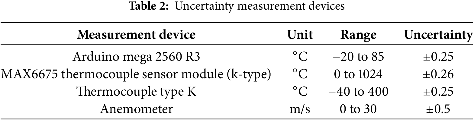
There is always a mistake between the measured value and the true value. In practical experiences, this difference is known as uncertainty. This occurs due to the limited accuracy of the measurement devices. Table 2 shows the uncertainty measurement devices. Therefore, any parameter calculated based on these measurements includes a simple error percentage. These proportions are few and do not affect the general results.
5.1.1 Coefficient of Performance (COP)
The temperature measurements were taken in the airspace of Iraq/Baghdad, with a temperature of 31°C. The coefficient of performance is shown in Fig. 8. The scientific explanation for the COP being greater than 1.2 is that this means Qc is larger than W. The Peltier device uses more than just electrical work to operate; it also relies on additional natural thermal effects. The Peltier effect occurs when an electric current flows through the junction of two different materials, causing heat to be absorbed or released at the junction. Heat transfer by water circulation using an auxiliary water-cooling system and air system to decrease the temperature of the hot junction of the TEC module. To remove hot air, place a fan on the roof on the hot side of the device. The fan is designed to extract hot air only due to its location. To get high efficiency, the hot and cold parts were isolated between the two junctions. The inner insulation is made of aluminium on the cold side and more than one layer of NBR on the hot side to make sure the heat will not be transferred from one side to the other side. The strategies maintained almost equal differences for all operating states, and the COP was stable at all times for operating periods. A COP value of more than 1.2 indicates, due to the design of the device, induced auxiliary system, water and air cooling systems, a dehumidifier system, and internal insulation to separate two parts of the device. The two-part separation process has been successful in getting high COP lifting since startup and ranges from 1.17 to 1.24 in the operation period of fifteen minutes. This thermoelectric air conditioning steady state in cooling mode is because of the presence of a DC power supply, the thermal insulation between the parts of the device, appropriate wires, and the cover of the device made with aluminium (aluminium has effectively contributed to improving the performance of the cooling system through its high heat transfer ability), and heat exchange are allowed to dissipate the hot air on the hot side. The device has a dehumidification system consisting of copper tubes designed to remove moisture using copper pipes due to the excellent copper properties of intensification on the surface of the pipes, getting rid of moisture removal from the air, and used to drain the condensed water resulting from the cooling process. The moisture is withdrawn from the cooling process, and the moisture is withdrawn from the air after the cooling process, then it condenses on the cold surface and is drained through pipes and out of the device to an aluminium tank (condensate collection tank). The copper tubes extending from nearby locations on the Peltier and its tank are to be eliminated.

Figure 8: COP related against time of air conditioning cooling mood
5.1.2 Cooling Capacity and Work Rate
Fig. 9 illustrates the relationship between Qc (cooling capacity) and W (work rate) over time. The amount of heat transferred (Qc) includes the heat absorbed from the cold source, and it is larger than the work rate (W). This means that the system benefits from the heat in the cold and moves it with the help of a lesser amount of work rate (W). The device transmits more heat energy than it consumes in electrical energy. This happens because of the ability to enhance heat transfer. The scientific explanation for the fact that Qc is slightly larger than W depends on the concept of the efficiency of cooling systems. The heat is removed from the cold source and transferred to the hot source. As the accumulation of heat limits the device’s ability to transfer heat efficiently, this disadvantage was overcome by the procedures (pushing hot air and pulling air away from it, isolating the two parts, and controlling the airflow speed on the hot side). A heat sink with fins improves heat transfer and air circulation between the fins, which reduces air buildup and gets rid of excess heat because of its negative impact on actual performance, making it prone to damage [38]. The system needs a smaller amount of work rate compared with Qc to transfer a relatively higher amount of heat, meaning that the system can transfer more waste in a small amount without the need to consume more additional electrical energy compared with the capacity. Water is an important reason for improving cooling performance by increasing heat transfer efficiency and reducing heat accumulation [39]. Internal insulation caused the temperature difference between the two parts of the device to be minimal. This led to an increase in Qc and made it stable throughout the operation. The range of Qc is 34.69 to 36.92 W. The range of work rate is 29.53 to 29.56 W.

Figure 9: Qc (Watt), Work rate (Watt) against time (minute)
5.1.3 Difference in Temperature (ΔT)
Fig. 10 shows the difference in temperature over 15 min. The temperature difference between the hot and cold junctions is represented by the range of ΔT, which spans from 11.13 degrees Celsius to 11.41 degrees Celsius; the value of 11.41 degrees Celsius was recorded in the first minute of operation when the hot junction’s startup temperature was noted as 41.94 degrees Celsius. The hot junction in the last minutes of operation was 16.14 degrees Celsius. Due to cooling the hot side in two stages, the temperature was controlled well to keep it at a small value. The air velocity coming out of the device was 1.3 m/s. The fans on the hot sides disperse heat when the hot air is pushed in the opposite direction of the Peltier component. This air is drawn through the fan in the roof. When separating the hot parts from the cold, make the cold parts drop fast. A roof fan was installed to avoid heat buildup (thermal accumulation) inside the device because the hot air is heavy and takes a little more time to release outside because of its weight. Continuing the operation requires that the cold temperatures drop more times to reach 4.96 degrees Celsius. Almost the same differences have been maintained since the start of operation because it has a close relationship to raising COP values and its stability. This is due to the convergence of its values throughout the time it takes to operate the device. Steady-state from the first minute of operation.

Figure 10: ΔT (Celsius) against time (minute)
Fig. 11 shows the relationship between the air in the cold side and the time. The temperature decreased through the operation time to 30.53 degrees Celsius in the first minute. The chart shows the temperature was 4.96 degrees Celsius fifteen minutes after the operation.

Figure 11: Cooling mood, the temperature on the cold side against time
Fig. 12 shows that the temperature coming out of the device (Tout), which is the temperature of the air from the outlet slot, was 30.35 degrees Celsius, and it gradually decreased throughout the operation until reaching 18.97 degrees Celsius in the fifteenth minute.

Figure 12: Output temperature (Celsius) with against (minute)
Fig. 13 shows a comparison between the current work and the refrigerator work using the Peltier effect. We used the Peltier type TEC1-12703, which experiences a temperature drop from 30.9 to 16.9 degrees Celsius in 20 min and 6 s, with a COP range of 0.47 to 0.52. The current work temperature drops from 30.53 to 4.96 degrees Celsius in the time of 15 min, and the COP ranges from 1.17 to 1.24. We conducted a comparison between the two works, focussing on the larger range.

Figure 13: Compare with [40] cop against time in cooling mood
Thermoelectric powered by a solar panel for a large cooler box, the size of the cooler box was 1000 × 500 × 400 mm, and inside the thermoelectric cooler box, a plastic water bottle containing 19 L. Using a mini channel filled with water for cooling the hot side of the Peltier module, the cold side of the TEC was connected to the inner heat sink. We utilized the thermoelectric type TEC2-25408. The results showed the lowest temperature on the thermoelectric cold side was 16.21°C. The COPs obtained ranged from 0.01 to 0.76. The techniques used are an aluminium block, a water tank, one radiator and two fans, a small pump, a mini channel flowing with water for cooling the hot side of the Peltier module, and an inner heat sink to absorb heat inside the cooler box. The results showed the lowest temperature on the thermoelectric cold side was 16.21°C. The COPs obtained ranged from 0.01 to 0.76. Fig. 14 shows Tc (cold junction of the TEM) of 16.21°C for the compared work and 4.96°C for the current work.

Figure 14: Compared with [41] Tc (cold junction) between compared work and the current work
In this research, a portable solar thermoelectric refrigerator, an aluminium sheet with a thickness of 0.3 cm and a dimension of 6.8 × 6.8 × 15 cm, was used for the refrigerator space. To get the most out of the thermoelectric module (TEM), five TEC1-12706 modules were linked together, and the heat released from the hot side of the module is used for heating at low temperatures. The cooling chamber used is a well-insulated rectangular container made of aluminium. Experimental results show the system at 40°C on the hot side. A higher coefficient of performance (COP) of 0.61 was obtained for both cooling and heating modes. The results indicated the setpoint temperature achieved without using any external power source. To prevent heat transfer from the high ambient temperature to the cold chamber, a thermocol material was used with excellent insulating properties. The techniques that have been used are heat sinks attached to the hot side of each TEM to enhance the heat transfer. The entire area of the fins was cooled efficiently using small fans, and the cooling chamber used is a well-insulated rectangular container made of aluminium. Fig. 15 shows the Th (hot junction) in cooling modes between the compared work and current work. The T in the compared work was 40°C, and the current work was 16.14°C.

Figure 15: Compare [42] Th (hot junction) between compared work and the current work
A thermoelectric system for air conditioning was built, and a testing enclosure was made from plywood and Styrofoam. The system operates with a DC power supply and three modules of thermoelectric TEC1-12730. A section containing fans was installed inside the container, and a fan is mounted on top of the cover, with two rectangular holes such that the direction of the air can be controlled by the flaps, which allow for the heat from the air to be properly transferred to the heat sinks. The coefficient of performance of the system is 0.465. The techniques that have been used are heat sinks and fans and two rectangular holes. The fan placed on the cover sucks into the device and circulates through the heat sinks and then blows through two rectangular holes, and a compressor is used to increase the pressure of the refrigerant and used to reduce the pressure of the fluid. During the heat ejection phase, the gas is condensed into a liquid at the exit. Comparing shows in Fig. 16, the COP of the compared work is 0.465, and the COP of the current work is 1.246.

Figure 16: Compare with [19] cop against time in cooling mood
In a heating mood, I turned off the radiator and the water-cooling system. The air velocity coming out of the device was 3 m/s.
Fig. 17 shows the relationship between the COP and time. The COP increases as time increases when ΔT between the two parts, the cold and the hot, increases. The COP range was 0.008 to 1.039. COP is equal to 1 obtained according to the design of this device, such as the cooling case, because the component (fan and heat sink) of the cold part was small compared with the component on the hot side. This means the cold did not dissipate, such as the cooling mood from the beginning of the operation.

Figure 17: Heating mood, COP against time (minute)
5.2.2 Heating Capacity and Work Rate
Fig. 18 explains the Qh with W according to the time operation period in heating mode. When Qh is small and W is the largest value, it is because the ΔT was small, which is why COP was few, but it increases gradually when there is an increase in ΔT. When the temperature of the hot part increases, it is because the cold part was maintained at a certain temperature. This is done by running the fan in the roof to pull the cold air that exists in the cold part and pull it out of the room. This means the COP increased in heating mode when ΔT increased when the Qh increased and in fourteen minutes the device was steady state (Qh was larger than work and remained stable after the fourteen minutes). The range of Qh was 0.30 to 42.38 W, and the work rate was 38.38 to 40.78 W.

Figure 18: Heating mood, Qh and W against time (minute)
5.2.3 Difference in Temperature
Fig. 19 shows the difference in temperature in a period of 15 min. The temperature significantly increased because the dispersants (fan and heat sink) on the cold side were smaller than those on the hot side. ΔT different differences since the start of operation because it has a different relationship to raising COP values in heating mode. When the ΔT was increased, the COP was increased too. The fans on the cold side disperse cold air. This air is drawn through the air in the roof. The hot part temperature has been increased. When separating the hot parts from the cold, make the hot part increase fast. The range of ΔT was 11.99 to 32.46 degrees Celsius.

Figure 19: Heating mood, ΔT against time (minute)
Fig. 20 shows the relationship between the air on the hot side and the time the temperature has increased. It was 33.93 degrees Celsius in the first minute, and the chart shows the temperature was 53.94 fifteen minutes after operation.

Figure 20: Temperature of hot against time (minute) of heating mood
Fig. 21 shows the temperature coming out of the device was 25.76 degrees Celsius, and the temperature gradually increases throughout the operation until it is 36.43 degrees Celsius in the 15th min.

Figure 21: Output temperature against time (minute) in heating mood
This research about a comprehensive experimental analysis of an innovative air conditioning system that uses the Peltier effect has employed various techniques such as water-cooling systems, fan systems, thermal insulation, and dehumidification systems. The device has significant improvements in COP.
• The innovative inner thermal insulation technique, which separates the hot junction from the cold junction, prevents heat transfer from the hot part to the cold part and helps maintain an almost equal temperature difference in cooling mode (11.41°C to 11.18°C) throughout a 15-min operation period. This means that reducing ΔT made the COP increase in cooling state; the COP range was 1.17 to 1.24, and in heating mode, when the ΔT increased, the COP increased; the range of ΔT in heating mode was 11.99°C to 32.46°C, and the range of COP in heating mode was 0.008 to 1.039).
• A novel water-cooling system technique that helps to raise COP because the water absorbs heat faster than the air; specific heat capacity for water and air under standard conditions: the specific heat of water is much higher.
• A novel fan in the roof contributes greatly and effectively to reaching a high COP due to the direction of the hot air movement upward due to the low air density because hot air behavior rises above due to its low density.
• The cooling and heating modes showcase its balanced energy usage.
• The important point to its performance lies in effective inner thermal insulation, which provides a versatile solution for thermal management and the insulation inherent properties of the Peltier effect.
• Future enhancements may focus on improving the insulation materials and refining the control mechanisms to further optimize the system’s overall efficiency.
Acknowledgement: We would like to express our sincere gratitude to the University of Technology.
Funding Statement: The authors received no specific funding for this study.
Author Contributions: Hind Abdulrahman Mahmood: conceived and designed the experiments; performed the experiments; data collection; analyzed and interpreted the data and tools; wrote the paper; funding the research; references collection. Ameer Abed Jaddoa: analysis tools or data; data collection, references collection. Mohammed K. A-Saadi: analysis tools or data; data collection; references collection. All authors reviewed the results and approved the final version of the manuscript.
Availability of Data and Materials: Data available within the article.
Ethics Approval: Not applicable.
Conflicts of Interest: The authors declare no conflicts of interest to report regarding the present study.
References
1. Shilpa MK, Abdul Raheman M, Aabid A, Baig M, Veeresha RK, Kudva N. A systematic review of thermoelectric Peltier devices: applications and limitations. Fluid Dyn Mater Process. 2023;19(1):187–206. doi:10.32604/fdmp.2022.020351. [Google Scholar] [CrossRef]
2. Sopian K, Abusaibaa GY, Jarimi H, Ibrahim A, Riffat S. Photovoltaic vapor compression air conditioning system with phase change material (PCM) storage tank. Front Heat Mass Transf. 2023;20(21):1–6. doi:10.5098/hmt.20.21. [Google Scholar] [CrossRef]
3. Duan M, Sun H, Lin B, Wu Y. Evaluation on the applicability of thermoelectric air cooling systems for buildings with thermoelectric material optimization. Energy. 2021;221(1):119723. doi:10.1016/j.energy.2020.119723. [Google Scholar] [CrossRef]
4. Gutierrez AD, Sezer H, Ramirez JL. Required thermal comfort conditions inside hospital operating rooms (ORsa numerical assessment. Front Heat Mass Transf. 2022;18(4):1–12. doi:10.5098/hmt.18.4. [Google Scholar] [CrossRef]
5. Zayed ME, Zhao J, Elsheikh AH, Zhao Z, Zhong S, Kabeel AE. Comprehensive parametric analysis, design and performance assessment of a solar dish/Stirling system. Process Saf Environ Prot. 2021;146:276–91. doi:10.1016/j.psep.2020.09.007. [Google Scholar] [CrossRef]
6. Gupta N, Bhatnagar A, Ulum A, Samim MD, Dwivedi D, Yadav D. Review on thermoelectric air conditioning system applications and technology. IOSR J Mech Civ Eng. 2021;18(1 Ser. I):7–18. doi:10.9790/1684-1801010718. [Google Scholar] [CrossRef]
7. Zhu W, Chen B, Wang L, Wang C. Recovery of solid oxide fuel cell waste heat by thermoelectric generators and alkali metal thermoelectric converters. Front Heat Mass Transf. 2024;22(5):1559–73. doi:10.32604/fhmt.2024.047351. [Google Scholar] [CrossRef]
8. Afsharİ F. Experimental study for comparing heating and cooling performance of thermoelectric Peltier. Politeknik Dergisi. 2020;23(3):889–94. doi:10.2339/politeknik.713600. [Google Scholar] [CrossRef]
9. Wan H, Cao T, Hwang Y, Oh S. A review of recent advancements of variable refrigerant flow air-conditioning systems. Appl Therm Eng. 2020;169:114893. doi:10.1016/j.applthermaleng.2019.114893. [Google Scholar] [CrossRef]
10. Harsito C, Pramudi G, Muslim R, Adika D, Kurniawan Y. Investigation of sandwich-type generator thermoelectric element power generation. Eng Sci. 2023;27:1016. doi:10.30919/es1016. [Google Scholar] [CrossRef]
11. Azahar AH, Mohamad RA, Harun MH, Zainal Abidin AF, Nor Shah MB, Mohd Nor R, et al. Development and evaluation of stove using Peltier effect: connection and temperature control. J Adv Res Fluid Mech Therm Sci. 2020;70(1):1–12. doi:10.37934/arfmts.70.1.112. [Google Scholar] [CrossRef]
12. Zhao J, Ma L, Zayed ME, Elsheikh AH, Li W, Yan Q, et al. Industrial reheating furnaces: a review of energy efficiency assessments, waste heat recovery potentials, heating process characteristics and perspectives for steel industry. Process Saf Environ Prot. 2021;147:1209–28. doi:10.1016/j.psep.2021.01.045. [Google Scholar] [CrossRef]
13. Elnaggar A, Sharaf S, Abedel Rehim Z, Mustafa H, El Zoghby H. Enhancing COP and cooling temperature for Peltier with decreasing power, and chemical composition negative effect by optimizing connection, position angle, and voltages. Egypt J Chem. 2024;67(13):453–9. doi:10.21608/ejchem.2024.257857.9051. [Google Scholar] [CrossRef]
14. Hasson AS, Gatea HT, Alwan AA, Jabbar MY, Abed AM. Experimental study the performance of hybrid serpentine solar collector in air conditioning system. Front Heat Mass Transf. 2022;18(1):1–6. doi:10.5098/hmt.18.5. [Google Scholar] [CrossRef]
15. Ding J, Zhao W, Jin W, Di CA, Zhu D. Advanced thermoelectric materials for flexible cooling application. Adv Funct Mater. 2021;31(20):2010695. doi:10.1002/adfm.202010695. [Google Scholar] [CrossRef]
16. Zhang Y, Liu J, Zheng Z, Fang Z, Zhang X, Gao Y, et al. Analysis of thermal comfort during movement in a semi-open transition space. Energy Build. 2020;225:110312. doi:10.1016/j.enbuild.2020.110312. [Google Scholar] [CrossRef]
17. Staveckis A, Borodinecs A. Impact of impinging jet ventilation on thermal comfort and indoor air quality in office buildings. Energy Build. 2021;235:110738. doi:10.1016/j.enbuild.2021.110738. [Google Scholar] [CrossRef]
18. Adeyanju AA, Manohar K. Design and analysis of a thermoelectric air-conditioning system. J Sci Res Rep. 2020:1–11. doi:10.9734/jsrr/2020/v26i430243. [Google Scholar] [CrossRef]
19. Anthony Ademola A. Theoretical and experimental analysis of a thermoelectric air-conditioning system. In: Morosuk T, Sultan M, editors. Low-temperature technologies. London, UK: IntechOpen; 2020. p. 59–75. doi:10.5772/intechopen.88664. [Google Scholar] [CrossRef]
20. Pal D, Ansari A, Behera KK. A report on design & setup of Peltier module based air cooler. Int J Recent Technol Eng. 2020;9(1):2458–63. doi:10.35940/ijrte.A3010.059120. [Google Scholar] [CrossRef]
21. Alam N, Salman Ali M, Sajid S, Sharma D, Hasan Z. Experimental investigation and analysis of cooling performance of solar thermoelectric refrigerator. Sol Energy. 2023;263(6–7):111892. doi:10.1016/j.solener.2023.111892. [Google Scholar] [CrossRef]
22. Aboelmaaref MM, Zayed ME, Elsheikh AH, Askalany AA, Zhao J, Li W, et al. Design and performance analysis of a thermoelectric air-conditioning system driven by solar photovoltaic panels. Proc Inst Mech Eng Part C J Mech Eng Sci. 2021;235(20):5146–59. doi:10.1177/0954406220976164. [Google Scholar] [CrossRef]
23. Kherkhar A, Chiba Y, Tlemçani A, Mamur H. Thermal investigation of a thermoelectric cooler based on Arduino and PID control approach. Case Stud Therm Eng. 2022;36(1):102249. doi:10.1016/j.csite.2022.102249. [Google Scholar] [CrossRef]
24. Lawal OM, Chang Z. Development of an effective TE cooler box for food storage. Case Stud Therm Eng. 2021;28(2):101564. doi:10.1016/j.csite.2021.101564. [Google Scholar] [CrossRef]
25. Wantha C. Experimental investigation of the influence of thermoelectric subcooler on the performance of R134a refrigeration systems. Appl Therm Eng. 2020;180:115829. doi:10.1016/j.applthermaleng.2020.115829. [Google Scholar] [CrossRef]
26. Zhang A, Li Y. Thermal conductivity of aluminum alloys—a review. Materials. 2023;16(8):2972. doi:10.3390/ma16082972. [Google Scholar] [PubMed] [CrossRef]
27. Chen S, Wang R, Wu F, Zhang H, Gao X, Jiang L. Copper-based high-efficiency condensation heat transfer interface consisting of superhydrophobic hierarchical microgroove and nanocone structure. Mater Today Phys. 2021;19:100407. doi:10.1016/j.mtphys.2021.100407. [Google Scholar] [CrossRef]
28. Lou D, Mei S, Wang B, Li T, Cao J, Yang Q, et al. Effect of stabilizing heat treatment on condensation heat transfer performance of laser micro-/nano-textured copper surface. J Mater Sci. 2021;56(5):3981–94. doi:10.1007/s10853-020-05454-0. [Google Scholar] [CrossRef]
29. Raghavendra CR, Hasavimath K, Naik K. Study on effectiveness of heat pipe heat exchanger with copper tube cylinders. Mater Today Proc. 2021;39(3):800–4. doi:10.1016/j.matpr.2020.09.652. [Google Scholar] [CrossRef]
30. Michalak P. Impact of air density variation on a simulated earth-to-air heat exchanger’s performance. Energies. 2022;15(9):3215. doi:10.3390/en15093215. [Google Scholar] [CrossRef]
31. Mohammed KH, Al-Mirani AE, Ali BM, Alomar OR. Impacts of using AlO nano particle to compressor oil on performance of automobile air conditioning system. Front Heat Mass Transf. 2024;22(3):839–54. doi:10.32604/fhmt.2024.052671. [Google Scholar] [CrossRef]
32. Abed Jaddoa A. Convection heat transfer analysis with flow resistance for mini-helically coiled tubes at supercritical pressures experimentally. Int J Heat Technol. 2021;39(3):817–24. doi:10.18280/ijht.390315. [Google Scholar] [CrossRef]
33. Salman MM, Mahdi MM, Ahmed MK. Optimization of solar powered air conditioning system using alternating Peltier power supply. Bull Electr Eng Inform. 2024;13(1):20–30. doi:10.11591/eei.v13i1.5864. [Google Scholar] [CrossRef]
34. Numan N, Mahdi M, Ahmed M. A comparative experimental study analysis of solar based thermoelectric refrigerator using different hot side heat sink. Eng Technol J. 2022;40(1):90–8. doi:10.30684/etj.v40i1.2058. [Google Scholar] [CrossRef]
35. Wang JB, Li XH, Wang J, Zhu T, Bao YC. Thermal performance evaluation of a thermoelectric cooler coupled with Corona wind. Appl Therm Eng. 2020;179(1):115753. doi:10.1016/j.applthermaleng.2020.115753. [Google Scholar] [CrossRef]
36. Numan NF, Mahdi MM, Ahmed MKL. Thermoelectric refrigerator driven by solar panels using electrical control of the refrigeration system (on/off). AIP Conf Proc. 2023;2834(1):040008. doi:10.1063/5.0176322. [Google Scholar] [CrossRef]
37. Tark Z, Hamed AJ, Khalifa AHN. Performance study of the thermoelectric personal cooler under different ambient temperatures. Int J Heat Technol. 2022;40(1):53–62. doi:10.18280/ijht.400107. [Google Scholar] [CrossRef]
38. Abed Jaddoa A, Hamad KA, Hameed AAJ. Fluid inflow and heat transfer enhancement: an experimental analysis of nanofluids in minichannel. Front Heat Mass Transf. 2023;20(18):1–9. doi:10.5098/hmt.20.18. [Google Scholar] [CrossRef]
39. Sirikasemsuk S, Wiriyasart S, Prurapark R, Naphon N, Naphon P. Water/nanofluid pulsating flow in thermoelectric module for cooling electric vehicle battery systems. Int J Heat Technol. 2021;39(5):1618–26. doi:10.18280/ijht.390525. [Google Scholar] [CrossRef]
40. Yashwanth MR, Jayaprakash N, Verma B, Negi RP, Singh A, Deshpande DB. Experimental study on Peltier module-based compressor-less mini solar powered refrigerator. Ilkogr Online. 2021;20(3):3391–400. doi:10.17051/ilkonline.2021.03.354. [Google Scholar] [CrossRef]
41. Mirmanto M, Syahrul S, Wirawan M, Sayoga IMA, Wijayanta AT, Mahyudin I. Performance of a thermoelectric powered by solar panel for a large cooler box. Adv Sci Technol Eng Syst J. 2020;5(1):325–33. doi:10.1109/ICSGRC49013.2020.9232625. [Google Scholar] [CrossRef]
42. Rahman SMA, Hachicha AA, Ghenai C, Saidur R, Said Z. Performance and life cycle analysis of a novel portable solar thermoelectric refrigerator. Case Stud Therm Eng. 2020;19(3):100599. doi:10.1016/j.csite.2020.100599. [Google Scholar] [CrossRef]
Cite This Article
 Copyright © 2025 The Author(s). Published by Tech Science Press.
This work is licensed under a Creative Commons Attribution 4.0 International License , which permits unrestricted use, distribution, and reproduction in any medium, provided the original work is properly cited.
 Downloads
 Citation Tools