
 Submit a Paper
 Propose a Special lssue
 Open Access
ARTICLE
Research on Variable Condition Properties and Experimental Verification of a Variable Cross-Section Scroll Expander
1 College of Energy Storage Technology, Shandong University of Science and Technology, Qingdao, 266590, China
2 College of Mechanical and Electronic Engineering, Shandong University of Science and Technology, Qingdao, 266590, China
3 College of Mechanical and Electronic Engineering, Qingdao City University, Qingdao, 266106, China
* Corresponding Author: Minghan Peng. Email:
Frontiers in Heat and Mass Transfer 2025, 23(4), 1185-1201. https://doi.org/10.32604/fhmt.2025.067244
Received 28 April 2025; Accepted 26 June 2025; Issue published 29 August 2025
 View Full Text
 Download PDF
Abstract
The scroll expander, as the core component of the micro-compressed air energy storage and power generation system, directly affects the output efficiency of the system. Meanwhile, the scroll profile plays a central role in determining the output performance of the scroll expander. In this study, in order to investigate the output characteristics of a variable cross-section scroll expander, numerical simulation and experimental studies were conducted by using Computational Fluid Dynamics (CFD) methods and dynamic mesh techniques. The impact of critical parameters on the output performance of the scroll expander was analyzed through the utilization of the control variable method. It is found that increasing the inlet pressure and temperature within a certain range can improve the output power of the scroll expander. However, the increase in temperature and meshing clearance leads to a decline in the overall output performance of the scroll expander, leading to a decrease in volumetric efficiency by 8.43% and 12.79%, respectively. The experiments demonstrate that under equal inlet pressure conditions, increasing the inlet temperature elevates both the rotational speed and torque output of the scroll expander. Specifically, compared to operating at normal temperatures, the output torque increases by 21.8% under high-temperature conditions. However, the rate of speed and torque variation decreases as a consequence of enlarged meshing clearance, resulting in increased internal leakage and reduction in isentropic efficiency.Keywords
With the high quality development of society, energy, as the foundation and power source of social development, plays a critical role in promoting the growth of the national economy and improving living standards. Vigorously developing a new energy system is a key measure to improve new productivity and realize Chinese-style modernization [1–4]. Currently, energy storage and power generation technologies, along with waste heat recovery technologies, have become the difficulties and hot spots in the world [5–7]. Among energy storage systems, compressed air energy storage (CAES) exhibits distinct advantages, including enhanced efficiency, cost-effectiveness, and eco-friendly characteristics with low carbon emissions, leading to its accelerated development in recent years [8–11]. The working process of the miniature compressed air energy storage system operates through two distinct phases: energy storage and energy release [12–14], in which the expander is the kernel component of the energy release module, and its working performance directly determines the output efficiency of the energy storage system [15].
De Lucia et al. [16] tested the expander using HFC-245fa as the working fluid. Research showed that the maximum isentropic efficiency is achieved when the expansion ratio is close to the scroll’s volumetric expansion ratio. Murthy et al. [17] investigated the properties of a four-intersection-vane rotary expander in an Organic Rankine Cycle (ORC) system and discussed the influence of lubrication on its performance. They further proposed an Artificial Neural Network and Genetic Algorithm modeling approach to achieve higher accuracy in the expander’s performance. Liu et al. [18] studied the relation between the expansion ratio and output torsion under equal discharge pressure and found a positive correlation between them. According to the simulation analysis, Kottapallia et al. [19] identified that mass flow, velocity, and pressure are significant factors affecting the property. Based on different inlet pressures, it is concluded that the vortex efficiency and volume efficiency change with the pressure ratio, which verifies the accuracy of the simulation results. Emhardt et al. [20] obtained the aerodynamic properties of the expander under different pressure ratios through the unsteady numerical simulation. Under the condition of low pressure, the expander has an over-expansion phenomenon, and under the condition of high pressure, the expander has an under-expansion phenomenon. The increase in pressure ratio leads to an increase in radial clearance of the expander, which causes an increase in internal leakage and reduces the output performance. Shi et al. [21] analyzed the influence of pressure and rotational speed on the output performance and isentropic efficiency of the scroll expander under different working conditions by using the CFD method. Pressure exhibits an inverse proportionality to both output performance and isentropic efficiency. Sun et al. [22] verified the accuracy of the thermodynamic model by the CFD method, and analyzed that the pressure within the suction cavity is the key factor impacting the output efficiency. Wei et al. [23] established a model and analyzed the vortex flow performance of the working cavity by three-dimensional unsteady numerical simulation. Due to the air inlet being blocked during the working process, pressure distortion occurs at the intake port, and the scale constantly changes. Singh et al. [24] simulated the flow characteristics of a scroll expander with CO2 as a working medium by the CFD method. The main reason for the Change in suction cavity volume is the blockage of the air inlet, which leads to uneven pressure distribution and a large number of velocity vortices. Wei et al. [25] used the CFD method to numerically simulate the output performance and isentropic efficiency of a variable base circular scroll expander under variable working conditions. The inlet pressure increased by 0.3 MPa, and the isentropic efficiency increased by 6.61%.
In this study, the geometric model of a circular involute variable cross-section scroll expander is the first established basis of the geometric approach of the scroll expander. Secondly, the fluid domain model inside the expander is extracted by using Boolean operations, and the flow field variation law of the scroll expander is studied by using dynamic mesh technology and the CFD method. Then, the output characteristics under various pressures, temperatures, and meshing clearances are analyzed. Finally, the rationality of the simulation is verified by experiments.
This study presents two main contributions. Firstly, a novel design of a scroll expander with a variable wall thickness was designed by utilizing the involutes of various base circles. The performance of the scroll expander was analyzed by manipulating different parameters. Secondly, the efficacy of the scroll expander’s performance was verified through a combination of simulation and experiments.
2 Geometric Theory of Scroll Expander
The variable cross-section scroll profile of a circular involute consists of two circular involutes with varied radius base circles, including circular involute I and circular involute II. The corresponding tooth profile equations are given in Eqs. (1) and (2).
The meshing of two circular involutes with different radius base circles must satisfy the following conditions [26]:
(1) n1, n2 are positive integers and n1 > n2;
(2) R2/R1 = n1/n2.
The specific variables of the scroll profile in this study are shown in Table 1. Overcutting occurs owing to the interposition between the part and the tool in processing, it is necessary to correct the head of the scroll teeth [27]. In this study, the tooth head correction method of double circular arc plus straight line is adopted, as shown in Fig. 1. The yellow part is the circular involute I, the blue part is the circular involute II, and the red part is the double circular arc plus straight tooth head correction.
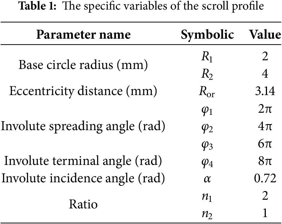

Figure 1: Schematic diagram of the scroll profile
2.2 Division of the Working Cavity
Following the operational procedure of the scroll expander, the working cavity is divided into four parts: suction cavity, expansion cavity I, expansion cavity II, and exhaust cavity, as shown in Fig. 2.

Figure 2: Diagram of the division of the scroll expander
The reasonable division of the fluid domain mesh plays an essential role in the accuracy of numerical simulation, and the quality of the mesh directly affects the accuracy, convergence, and reliability of numerical solution [28,29]. In the Mesh module, the sweep method is selected in the computational fluid domain, and the mesh unit size is set to 0.8 mm. To ensure the mesh quality, the free surface mesh types are selected to be all triangular, and the free surface mesh types of other cavities are selected to combine with triangular and quadrilateral. Since the meshing clearance between the orbiting and fixed scroll in the working cavity is 0.1 mm, the mesh size at the meshing area increases or decreases sharply. Therefore, the method of capturing the proximity factor is adopted to mitigate the mesh mutation, the minimum proximity size is set to 0.1 mm, and the proximity clearance factor is set to 3. Fig. 3 shows the results of the meshing in the working cavity, with 713,763 mesh nodes, 860,227 meshes. The maximum skewness is 0.78, and the minimum orthogonal quality is 0.16.

Figure 3: Mesh division of the fluid domain of the working cavity
In practical engineering calculations, for the purpose of ensuring the computation precision, selecting an adequate number of grids can efficaciously increase the computation efficiency [30]. Therefore, mesh independence verification is required.
Fig. 4 shows the relation between the quantity of meshes and output characteristics. As the number of grids increases, the inlet flow and output power change significantly. Within the range of 0.4~0.7 million grids, there is a significant variation in the curves. After the number of 0.7 million grids, the change tends to be stable. Therefore, the number of meshes in the range of 0.7~0.8 million can meet the calculation accuracy and effectively improve calculation efficiency.
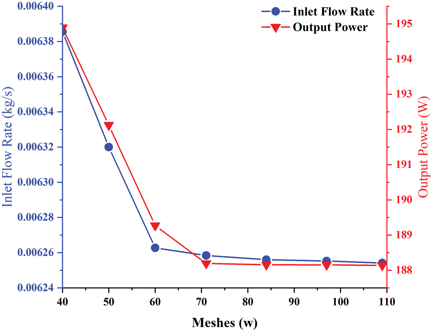
Figure 4: The relation between the quantity of meshes and output characteristics
2.4 Boundary Condition Setting
(1) Select the transient solver, and utilize the RNG k-ε model as the physical model.
(2) Set the port as a pressure boundary. The inlet and outlet pressures are set to 0.6 and 0.1 MPa, respectively. The inlet and outlet temperatures are set to 373 and 300 K, respectively.
(3) The working medium selects ideal air.
(4) The dynamic mesh model selects spring smoothing, 2.5D plane reconfiguration. In the dynamic mesh area, the orbiting scroll area is defined as a rigid body, with the working cavity’s upper and lower surfaces designed as deformation areas, and other areas set to static areas [31].
(5) Due to the PISO algorithm can efficiently reduce the effect of mesh aberration on the astringency of computation. Therefore, this study uses the PISO algorithm to emulate and compute [32].
3 Research on the Output Characteristics under Varying Working Conditions
3.1 Influence of the Output Characteristics under Different Pressures
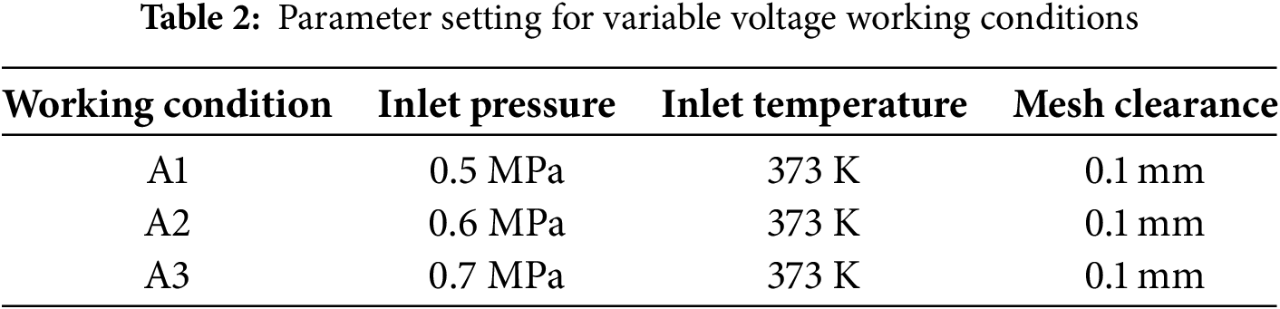
Under the condition of the same temperature and meshing clearance, the inlet pressure setting parameters are shown in Table 2. Study the effects of different pressures on the inlet and outlet flow rates, gas force, output torque, and output power.
As shown in Fig. 5a, as the increase of inlet pressure, the gas density rises and the gas flow rate increases, resulting in a higher inlet flow rate under A3 conditions compared to the other two operational scenarios. Owing to the eccentric rotation of the working cavity, which causes the tooth head to continuously block the air inlet, the air inlet is throttled, and the inlet flow rate is constantly changing. Around the spindle rotation angle of 106°, the air inlet is completely blocked, and the inlet flow rate reaches a minimum. Fig. 5b shows that the outlet flow rate is mainly affected by exhaust back pressure and atmospheric pressure. As the increase of inlet pressure, the differential pressure between the adjacent working cavities increases, and the outlet flow rate increases. However, the outlet flow rate is not completely proportional to the inlet pressure. When the pressure is too large, the mutual friction and collision between the gases in the back pressure cavity will be intensified, the degree of scroll is increased, the local pressure of the back pressure cavity is distorted, and the flow rate is reduced. In the range of 0°~30° of spindle angle, the exhaust back pressure is less than the atmospheric pressure, and the gas accelerates to flow out under the action of inertial force and forward differential pressure, and the outlet flow rate increases. In the range of 30°~60° of the spindle angle, the high pressure gas flows form the exhaust cavity into the back pressure cavity, the exhaust back pressure increases, the gas is subjected to the resistance of the reverse pressure difference and the mechanical energy loss of the gas, and the outlet flow rate decreases.

Figure 5: Changes in inlet and outlet flow rate under variable pressure conditions: (a) Inlet flow rate, (b) Outlet flow rate
As shown in Fig. 6, as the increase of inlet pressure, both the aerodynamic force and the output torque increase, and the tangential force increases faster than the axial force. It is further proved that the output torque and output efficiency can be promoted by properly increasing the inlet pressure. When the spindle angle is 141°~164° in the A1 condition, the direction of radial force changes, which leads to a decrease in spindle eccentricity, an increase in radial clearance, and a decrease in output performance. No radial force change is found in A2 and A3 conditions, which proves that appropriately increasing the inlet pressure could help alleviate tangential leakage.

Figure 6: Changes in aerodynamic force and torque under variable pressure conditions: (a) Tangential force, (b) Radial force, (c) Axial force, (d) Output torque
Fig. 7 shows the output characteristics under different inlet pressure conditions. With the increase of inlet pressure, the gas density increases, and the average flow rate rises. Compared with the A1 condition, the average hourly flow rate of the A2 condition increases by 29.7%. Compared with the A2 condition, the average hourly flow rate of the A3 condition increases by 11.6%. Therefore, the increase in average time flow rate does not increase proportionally with the increase in inlet pressure. With the increase of inlet pressure, the average power of the scroll expander increases. Compared with the A1 condition, the average hourly power increase of the A2 condition is 24.58%. Compared with the A2 condition, the average hourly power increase of the A3 condition is 30.19%. The isentropic efficiency of the scroll expander increases sharply with the increase in expander inlet pressure and increases by 44.43% when the expander inlet pressure increases from 0.5 to 0.7 MPa. Meanwhile, the volumetric efficiency increases by 7.41%.

Figure 7: Changes in output characteristics under variable pressure conditions: (a) Changes in hourly average flow and power; (b) Changes in volumetric and isentropic efficiency
3.2 Influence of the Output Characteristics under Different Temperatures
Under the conditions of the same pressure and meshing clearance, the inlet temperature setting parameters are shown in Table 3. Research the effects of different temperatures on the inlet and outlet flow rates, gas force, output torque, and output power.
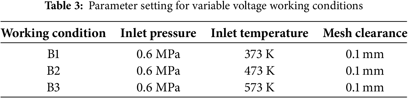
Fig. 8a shows that as the inlet temperature increases, the gas density decreases, and the gas density is positively correlated with the gas mass, and a decrease in the inlet flow rate. Because of the periodic obstruction of the orbiting scroll, the inlet is throttled, and the overall inlet flow rate shows a decreasing trend followed by an increasing trend. When the spindle angle is 106°, the cross-sectional area of gas flow is smallest, and the inlet flow rate reaches the minimum. Fig. 8b shows that under the same inlet pressure, as the inlet temperature increases, the vortex intensity in the working cavity increases, the mechanical loss is serious, and the decrease of outlet flow rate is greater than that of the inlet flow rate.
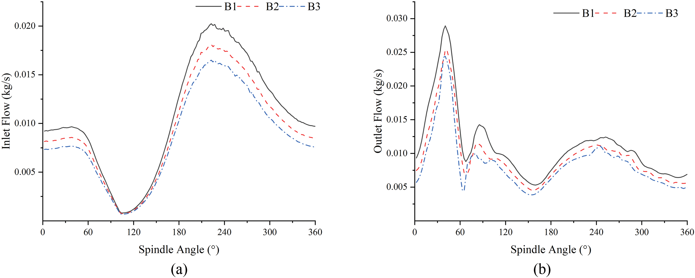
Figure 8: Change in inlet and outlet flow rate under variable temperature conditions: (a) Inlet flow rate, (b) Outlet flow rate
Fig. 9 shows that with the inlet temperature increase, the gas density decreases, the inlet and outlet flow rate decreases, the differential pressure between adjacent working cavities increases, and the aerodynamic force and output torque increase accordingly. The radial force and axial force have an obvious downward trend compared with the increase of the tangential force. The decrease of axial force and tangential force helps to reduce tangential and radial leakage and improve the output performance of the scroll expander.


Figure 9: Changes in aerodynamic force and torque under variable temperature conditions: (a) Tangential force, (b) Radial force, (c) Axial force, (d) Output torque
As shown in Fig. 10, with the increase of inlet temperature, the average flow rate decreases, which is caused by the increase of inlet temperature, the decrease of gas density and mass flow rate, and the increase of pressure difference between adjacent working cavities. Under the three working conditions of B1, B2, and B3, the average hourly flow decreases by 9.73% and 9.3%, respectively, and the average power increases by 10.2% and 5.23%. The isentropic efficiency of the scroll expander decreases sharply with the increase in expander inlet temperature and decreases by 37.27% when the expander inlet temperature increases from 373 to 573 K. Meanwhile, the volumetric efficiency decreases by 8.43%.

Figure 10: Changes in output characteristics under variable temperature conditions: (a) Changes in hourly average flow and power; (b) Changes in volumetric and isentropic efficiency
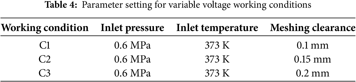
3.3 Influence of the Output Characteristics under Different Meshing Clearances
In actual working conditions, the orbiting and fixed meshing clearance is kept within the range of 0.1~0.2 mm. Therefore, in this study, the orbiting and fixed meshing clearance setting parameters are shown in Table 4. Study the effects of different meshing clearances on the inlet and outlet flow rates, gas force, output torque, and output power.
As shown in Fig. 11a, under different orbiting and fixed meshing clearances, the meshing clearance is positively correlated with the inlet flow rate. The inlet flow rate change increases over time due to the throttling action of the orbiting scroll tooth head and tangential leakage resulting from the orbiting and fixed meshing clearance. The changing amplitude of import flow in a period can be divided into a rapid decline stage, a slow rise stage, and a slow decline stage. When the spindle rotation angle is 90°~150°, due to the increase of radial clearance and serious tangential leakage, the inlet flow rate of C2 and C3 conditions decreases at a faster rate than that of C1 conditions. As shown in Fig. 11b, in the range of spindle rotation angle 90°~150°, due to the serious tangential leakage, the inlet flow rate drops sharply under C2 and C3 conditions, resulting in the reflux phenomenon of the outlet flow rate.

Figure 11: Change in inlet and outlet flow rate under varying meshing clearance: (a) Inlet flow, (b) Outlet flow rate
Fig. 12 shows that as the increase of the meshing clearance of the orbiting scroll, the tangential and axial forces decrease, while the radial force increases. The decrease in tangential force is greater than the decrease in axial force, which proves that the increase in meshing clearance will lead to an increase in leakage of the working cavity and a decrease in output efficiency. Within the range of 90°~150° of the spindle angle, the tangential force, axial force, and radial force under C2 and C3 conditions show obvious phase differences. Due to the increase in the throttling action of the air inlet, the inlet flow is very small, and there is a certain pressure difference between each working cavity. The increase of meshing clearance will lead to tangential leakage of the adjacent working cavity, the pressure difference in the adjacent working cavity, and the gas force will also decrease accordingly.

Figure 12: Changes in aerodynamic force and torque under varying meshing clearance: (a) Tangential force, (b) Radial force, (c) Axial force, (d) Output torque
As shown in Fig. 13, the average hourly flow is proportional to the meshing clearance, and the average hourly power is inversely proportional to the meshing clearance. Compared with the C1 condition, the average flow rate of the C2 condition increased by 36.64%, and the average power of the C2 condition decreased by 24.26%. Compared with the C2 condition, the average flow rate of the C3 condition increased by 7.75%, and the average power of the C3 condition decreased by 8.03%. With the increase of meshing clearance, the increase or decrease of average hourly flow rate and average hourly power gradually tends to be stable. The isentropic efficiency of the scroll expander decreases sharply with the increase in expander meshing clearance and decreases by 53.71%. Meanwhile, the volumetric efficiency decreases by 12.79%.

Figure 13: Changes in output characteristics under varying meshing clearance: (a) Changes in hourly average flow and power; (b) Changes in volumetric and isentropic efficiency
Fig. 14 shows the test bench of the micro-compressed air energy storage and power generation system. The system can be divided into an energy storage module, a heating module, an energy release module, and an information acquisition module.

Figure 14: Schematic diagram of the micro-compressed air energy storage power generation system
4.2 Analysis of Experimental Results
Fig. 15a,b illustrates a series of inlet pressure settings at 0.6, 0.5, 0.4, and 0.3 MPa over a defined timeframe. Decreasing inlet pressure correlates with reductions in inlet flow rate, rotational speed, and output torque. The gradual nature of the pressure regulation process leads to incremental pressure drops. Signal acquisition delays for rotational speed and output torque result in notable fluctuations, yet the overall trends align with inlet pressure changes. Inlet flow rate, rotational speed, and output torque exhibit fluctuations within the ranges of 190 L/min, 243 r/min, and 1.02 N·m, respectively.

Figure 15: Changes in pressure, temperature, flow rate, speed, and output torque at the inlet and outlet of the scroll expander: (a) Temperature and pressure change at inlet and outlet of scroll expander, (b) Changes in inlet flow rate, rotational speed and output torque of scroll expander
As shown in Fig. 16, under the same inlet pressure condition, the higher the inlet temperature, the higher the speed and output torque of the variable cross-section scroll expander. Under the inlet pressure of 0.3~0.6 MPa, the output torque of the high-temperature variable cross-section scroll expander is increased by 21.8% compared with that of the normal-temperature variable cross-section scroll expander.

Figure 16: Changes in rotational speed and output torque of the scroll expander at different temperatures
With rising inlet pressure, the rate of change in speed and output torque of the variable cross-section scroll expander decreases at high temperatures. The high-pressure and high-temperature environment causes deformation in both orbiting and fixed scrolls, resulting in a larger meshing clearance, increased internal leakage, and reduced working efficiency.
(1) The effect of key parameters on the output performance of the scroll expander was analyzed by using the control variable method. The results show that the output performance of the scroll expander could be improved by increasing the inlet pressure and temperature within a certain range. However, beyond a certain range, the deformation of the orbiting and fixed scroll leads to an increase in the meshing clearance, causing an increase in internal leakage and a decrease in work efficiency.
(2) Experimental results demonstrate that a reduction in inlet pressure correlates with decreases in inlet flow rate, rotational speed, and output torque. Conversely, under consistent inlet pressure, elevated inlet temperatures correspond to increased speed and output torque. In comparison to a variable cross-section scroll expander operating at normal temperatures, the output torque increases by 21.8% at high temperatures. Nevertheless, the rate of change in speed and output torque of the variable cross-section scroll expander diminishes under high-temperature conditions due to an enlargement of the meshing clearance, resulting in increased internal leakage and reduced operational efficiency.
Acknowledgement: The authors would like to thank the research grant support from the Youth Innovation Team of universities in Shandong Province.
Funding Statement: This work was funded by the National Key Research and Development Program of China (No. 2024YFE0208100).
Author Contributions: Junying Wei: Conceptualization, methodology, formal analysis, resources, supervision; Guangxian Yin: software, validation, data curation, writing—original draft preparation, writing—review and editing; Minghan Peng: investigation, project administration; Jihao Zhang: investigation, visualization; Zhengyi Li: data curation; Wenwen Chang: visualization; Chenrui Zhang: project administration, visualization; Long Chang: resources, supervision, funding acquisition. All authors reviewed the results and approved the final version of the manuscript.
Availability of Data and Materials: The datasets used or analyzed during the current study are available from the corresponding author on reasonable request. Data openly available in a public repository.
Ethics Approval: Not applicable.
Conflicts of Interest: The authors declare no conflicts of interest to report regarding the present study.
References
1. Lin K. The politics of ambiguity: local strategies in China’s energy policy and governance. Energy Res Soc Sci. 2025;122(2):103985. doi:10.1016/j.erss.2025.103985. [Google Scholar] [CrossRef]
2. Wen X, Cao X, Wang L, Wen J, Yu Z. New urbanization and low-carbon Energy transition in China: coupling coordination, spatial-temporal differentiation, and spatial effects. Sustainability. 2025;17(8):3352. doi:10.3390/su17083352. [Google Scholar] [CrossRef]
3. Tan Z, Jiang Z, Zhao H. Research on the construction of a new green and low CARBON energy system and the enhancement of new quality productivity. J North China Electr Power Univ. 2024;6:27–35. (In Chinese). doi:10.14092/j.cnki.cn11-3956/c.2024.06.004. [Google Scholar] [CrossRef]
4. Feng J. Research on new energy industry empowering green and high quality development. Trade Fair Econ. 2024;24:133–6. (In Chinese). doi:10.19995/j.cnki.CN10-1617/F7.2024.24.133. [Google Scholar] [CrossRef]
5. Hans Joshua CC, Christian MD, Jaime H. Storage is the new black: a review of energy storage system applications to resolve intermittency in renewable energy systems. Energies. 2025;18(2):354. doi:10.3390/en18020354. [Google Scholar] [CrossRef]
6. Ding Y, Liu Y, Chai Y, Han Y, Olumayegun O, Wang M. Energy analysis and economic evaluation of trigeneration system integrating compressed air energy storage system, organic Rankine cycle with different absorption refrigeration systems. J Energy Storage. 2024;75(1):109552. doi:10.1016/j.est.2023.109552. [Google Scholar] [CrossRef]
7. Hamid Reza R, Brian E, Evangelos B, Christos T, Ahmad A. Thermochemical technologies for industrial waste heat recovery: a comprehensive review. Renew Sustain Energy Rev. 2025;215(4):115598. doi:10.1016/j.rser.2025.115598. [Google Scholar] [CrossRef]
8. Su X, Liu C, Guo D, Xu Y, Zhang H, Chen H, et al. Experimental study on the characteristics of energy airbags for underwater compressed air energy storage. J Energy Storage. 2025;118:116283. doi:10.1016/j.est.2025.116283. [Google Scholar] [CrossRef]
9. Yuan Z, Yang Y. Research status and Development trend of compressed air energy storage technology. South Energy Constr. 2024;11(2):146–53. (In Chinese). doi:10.16516/j.ceec.2024.2.14. [Google Scholar] [CrossRef]
10. Zhang R, Zhao G. A comprehensive review of compressed air energy storage technologies: current status and future trends Available to Purchase. J Renew Sustain Energy. 2025;17(2):022702. doi:10.1063/5.0246214. [Google Scholar] [CrossRef]
11. Zhang L, Xie M, Ye K, Li S, Chen L. Compressed air energy storage based on variable-volume air storage: a review. J Energy Storage. 2025;110:115361. doi:10.1016/j.est.2025.115361. [Google Scholar] [CrossRef]
12. Maffulli G, Grimaldi A, McGillis A, Succi L, Przybytko P, Maceli N, et al. A Perspective on the process and Turbomachinery design of compressed air energy storage systems. J Eng Gas Turbines Power-Trans ASME. 2025;147(3):1–21. doi:10.1115/1.4066250. [Google Scholar] [CrossRef]
13. Li J, Li X, Wei F, Yan P, Liu J, Yu D. Research on techno-economic evaluation of new type compressed air energy storage coupled with thermal power unit. Proc CSEE. 2023;43(23):9171–83. doi:10.13334/j.0258-8013.pcsee.222819. [Google Scholar] [CrossRef]
14. Zheng H, Xu Y, Zhang H, Zhang J, Yang F, Yang H, et al. Performance study of integrated compressor/expander based on small-scale compressed air energy storage system. J Energy Storage. 2025;105(2):114689. doi:10.1016/j.est.2024.114689. [Google Scholar] [CrossRef]
15. Iglesias A, Favrat D. Innovative isothermal oil-free co-rotating scroll compressor-expander for energy storage with first expander tests. Energy Convers Manag. 2014;85(14):565–72. doi:10.1016/j.enconman.2014.05.106. [Google Scholar] [CrossRef]
16. De Lucia M, Pierucci G, Manieri M, Agostini G, Giusti E, Salvestroni M, et al. Experimental characterization of commercial scroll expander for micro-scale solar ORC application: part 1. Energies. 2024;17(9):2205. doi:10.3390/en17092205. [Google Scholar] [CrossRef]
17. Murthy A, Naseri A, Shenoy P, Patil I. Experimental investigation and ANN analysis of a four-intersecting-vane rotary expander in a micro-scale organic Rankine cycle system. Appl Therm Eng. 2024;243(5):122501. doi:10.1016/j.applthermaleng.2024.122501. [Google Scholar] [CrossRef]
18. Liu Z, Wu H, Lin X, Song P. Unsteady flows of a scroll expander under various types of expansion process. Energy Storage Sci Technol. 2019;8(6):1241–6. doi:10.12028/J.ISSN.2095-4239.2019.0119. [Google Scholar] [CrossRef]
19. Kottapallia A, Konijeti R. Numerical and experimental investigation of nonlubricated air scroll expander derived from a refrigerant scroll compressor. Front Heat Mass Transf. 2022;19(1):1–11. doi:10.5098/hmt.19.11. [Google Scholar] [CrossRef]
20. Emhardt S, Song P, Tian G, Chew J, Wei M. CFD analysis of variable wall thickness scroll expander integrated into small scale ORC systems. Energy Proc. 2019;158(1):2272–7. doi:10.1016/j.egypro.2019.01.241. [Google Scholar] [CrossRef]
21. Shi L, Zhao Y, Peng B. Based on the study of variable operating conditions and experimental verification of a small-scale ORC with a scroll expander. Therm Power Gener. 2024;53(1):115–23. (In Chinese). doi:10.19666/j.rlfd.202306095. [Google Scholar] [CrossRef]
22. Sun J, Peng B, Zhu B, Li Y. Research on the performance characteristics of an oil-free scroll expander that is applied to a micro-scale compressed air energy storage system. J Energy Storage. 2023;63:106896. doi:10.1016/j.est.2023.106896. [Google Scholar] [CrossRef]
23. Wei M, Song P, Zhao B, Shi L, Wang Z, Ma C. Unsteady flow in the suction process of a scroll expander for an ORC waste heat recovery system. Appl Therm Eng. 2015;78:460–70. doi:10.1016/j.applthermaleng.2015.01.010. [Google Scholar] [CrossRef]
24. Singh S, Singh A, Dasgupta M. CFD modeling of a scroll work recovery expander for trans-critical CO2 refrigeration system. Energy Proc. 2017;109:146–52. doi:10.1016/j.egypro.2017.03.081. [Google Scholar] [CrossRef]
25. Wei J, Li G, Zhang C, Chang W, Wang J. Analysis of profile and unsteady flow performance of variable base circle radius scroll expander. Front Heat Mass Transf. 2023;21(1):199–214. doi:10.32604/fhmt.2023.041793. [Google Scholar] [CrossRef]
26. Zhang P, Peng B, Zhang Y. Method and theory of establishing variable thickness scrolls based on circle involute. J Jilin Univ. 2022;52(4):789–98. (In Chinese). doi:10.13229/j.cnki.jdxbgxb20200881. [Google Scholar] [CrossRef]
27. Liu Z, Xie D, Li Z, Huang T, Liu Z. Effect of tooth head modification on the performance of a scroll expander for ORC waste heat recovery system. Front Energy Res. 2023;10:1088719. doi:10.3389/fenrg.2022.1088719. [Google Scholar] [CrossRef]
28. Sun S, Wu K, Guo P, Yan J. Analysis of the three-dimensional transient flow in a scroll refrigeration compressor. Appl Therm Eng. 2017;127:1086–94. doi:10.1016/j.applthermaleng.2017.08.115. [Google Scholar] [CrossRef]
29. Wang J, Han Y, Pan S, Wang Z, Cui D, Geng M. Optimal design and development of an oil-free double-scroll air compressor used in a PEM fuel cell system. Renew Energy. 2022;199:840–51. doi:10.1016/j.renene.2022.08.154. [Google Scholar] [CrossRef]
30. Wei J, Li G, Yin G, Chang W, Zhang C, Li X, et al. Analysis of flow characteristics at the inlet of a circular involute variable wall thickness scroll expander. Processes. 2023;11(11):3117. doi:10.3390/pr11113117. [Google Scholar] [CrossRef]
31. Chang J, Chang C, Huang T, Lin J, Huang K. Experimental study and CFD approach for scroll type expander used in low temperature organic Rankine cycle. Appl Therm Eng Des Process Equip Econ. 2014;73(2):1444–52. doi:10.1016/j.applthermaleng.2014.08.050. [Google Scholar] [CrossRef]
32. Emhardt S, Tian G, Song P, Chew J, Wei M. CFD analysis of the influence of variable wall thickness on the aerodynamic performance of small scale ORC scroll expanders. Energy. 2022;244:122586. doi:10.1016/j.energy.2021.122586. [Google Scholar] [CrossRef]
Cite This Article
 Copyright © 2025 The Author(s). Published by Tech Science Press.
This work is licensed under a Creative Commons Attribution 4.0 International License , which permits unrestricted use, distribution, and reproduction in any medium, provided the original work is properly cited.
 Downloads
 Citation Tools