
 Submit a Paper
 Propose a Special lssue
 Open Access
ARTICLE

Fuzzy Feedback Control for Electro-Hydraulic Actuators
1 School of Engineering-Technology, Thu Dau Mot University, Thu Dau Mot City, 590000, Vietnam
2 Faculty of Engineering-Technology, Nguyen Tat Thanh University, Ho Chi Minh City, 754000, Vietnam
3 Hue Industrial College, Hue City, 530000, Vietnam
4 Robotics and Mechatronics Lab, University of Ulsan, Ulsan City, 44610, Korea
* Corresponding Author: Huy Q. Tran. Email:
Intelligent Automation & Soft Computing 2023, 36(2), 2441-2456. https://doi.org/10.32604/iasc.2023.033368
Received 15 June 2022; Accepted 19 August 2022; Issue published 05 January 2023
 View Full Text
 Download PDF
Abstract
Electro-hydraulic actuators (EHA) have recently played a significant role in modern industrial applications, especially in systems requiring extremely high precision. This can be explained by EHA’s ability to precisely control the position and force through advanced sensors and innovative control algorithms. One of the promising approaches to improve control accuracy for EHA systems is applying classical to modern control algorithms, in which the proportional–integral–derivative (PID) algorithm, fuzzy logic controller, and a hybrid of these methods are popular options. In this paper, we developed a novel version of the fuzzy control algorithm and linear feedback control method, namely fuzzy linear feedback control, to improve the control performance. To achieve the highest performance, we first designed a mathematical EHA model based on the Matlab/Simulink software packages thanks to the selected parameters, which are similar to a real EHA system. Then, we respectively applied PID, fuzzy PID (FPID), and fuzzy linear feedback control (FLFC) before comparing them to have a full view of the outstanding advantages of the proposed algorithm. The simulation results showed that the proposed FLFC algorithm is approximately 99% and 77% superior in performance to the PID and feedback control algorithms, respectively.Keywords
Recently, electro-mechanical actuation (EMA) systems have gradually replaced traditional hydraulic actuation (HA) systems because the EMA systems excel in low weight and outstanding versatility. However, these systems also face significant challenges related to energy performance due to the screw mechanism. To overcome the limitations of the HA system and take advantage of the advantages of the electrical system, a hybrid hydraulic and electrical system, called electro-hydraulic actuators (EHA), was developed [1]. EHA systems are outstanding for excellent power to weight ratio, fast and smooth response, high stiffness, and precise positioning; therefore, these systems have become an integral part of drives in modern industrial applications, including airplanes, robotics, surgery, construction, and many other industrial types of machinery [2,3].
In robotics applications, we can use EHA systems to create drive systems with high load capacity and a large power density ratio [4]. The authors [5] leveraged EHA to develop a legged robot using model predictive trajectory tracking control with a multi-scale online estimator. Similarly, the authors in [6] developed an EHA system for an exoskeleton robot. A bidirectional pump was used to achieve higher speed rotation and better pressure than the traditional gear pump. Besides legged and exoskeleton robots, a robotic joint with circular EHA is also an exciting research direction [7]. In this work, the authors combined the motion characteristic of a rotary motor and a simple structure for hip flexion and extension using an adequate torque source. A distinctive feature of robotic arm systems when using micro-EHA is that these robots have lightweight and high pay-load handling capacity. Utilizing the above advantages, Lee et al. [8], developed a bio-mimetic robot arm that is 2.2 Kg in weight and can lift an object weighing approximately 5 Kg. This system has demonstrated that robotic arms with the mini-EHA system can achieve higher power than their weight. In general, robotic arms with small size and light load capacity can use electric actuators [9,10]. In contrast, EHA is used to develop many heavy-duty applications because it can carry heavy loads with high accuracy and low cost.
In addition to applications in the robotic field, EHA systems are also applicable to many subjects. Some of the typical applications are primary flight control, landing gear application, wind energy, and transportation applications. In [11], the authors provided a comprehensive overview of different types of EHA systems. Difficulties arising in using an independent metering valve are also an issue that needs to be addressed [12]. In this system, the authors considered moderate faults of activated valves and inactivated faults using an active fault-tolerant control (FTC) system. Furthermore, fault modeling for gas turbine control systems is also interesting [13]. In this work, the authors established an EHA fault diagnosis model based on the EHA mechanism modeling. These studies have partly demonstrated the effectiveness of EHA systems in various industrial fields [14–21].
One of the complex problems when designing EHA applications is developing and optimizing control algorithms to improve control performance. To simultaneously achieve high accuracy and high performance, the proportional–integral–derivative (PID) controller is first applied. In [22], Skarpetis et al., deployed a robust PID controller to control the position of EHA under the detrimental effect of physical uncertainties and external disturbances. In reality, selecting P, I, and D parameters in nonlinear systems is arduous. Therefore, Shern et al., conducted a study to compare PID parameter selection based on several techniques such as the Ziegler-Nichols tuning method, conventional Particle Swarm Optimization technique, and Priority-based Fitness Particle Swarm Optimization (PFPSO). The obtained results showed that all methods achieve specific effects, in which PFPSO outperformed the rest [23]. In another attempt to optimize PID parameters, Tajjdin et al., used the Nelder-Mead method to tune these parameters to their optimum values [24]. Simulation and real-time studies showed that the proposed model provided the best response although the system had a minor percentage of best fit. In addition, the researchers also used fuzzy and PID algorithms to perform the self-tuning process. Through this fine-tuning process, we obtained the most suitable PID values [25,26].
In addition to PID, fuzzy logic is also a promising approach. In [27], the authors developed an improved version of the fuzzy method called fractional-order fuzzy logic position and force control for the EHA servo system. The experimental results showed that the proposed solution achieved better performance criteria. Based on fuzzy techniques and finite impulse response, Choi et al., developed a fuzzy finite memory state estimation for electro-hydraulic active suspension systems, which was more robust than the existing infinite impulse response nonlinear estimator in terms of external disturbances and modeling uncertainties [28]. The similar approaches were showed in [29,30]. To achieve higher performance, many researchers leveraged a hybrid of fuzzy and other techniques, such as PID and particle swarm optimization (PSO). In [31], the authors applied fuzzy adaptive PID control to improve further the EHA system’s robustness based on its mathematical modeling and Matlab/Simulink simulation. To reduce the chattering significantly, Daniel et al., optimized fuzzy logic controller parameters using the PSO algorithm. In this approach, the authors tuned the scaling factors of the fuzzy inference system to obtain optimal values, and this process assisted the system in achieving the best performance [32]. Fuzzy logic and other control algorithms have brought many positive effects [33–36].
Inspired by the above pieces of literature, this paper proposes a novel solution for EHA systems, which aims to achieve the following objectives:
• Designing a mathematical EHA model on Matlab/Simulink with selected parameters similar to real systems
• Proposing a novel control algorithm based on a combination of fuzzy logic and linear feedback controller (LFC), namely Fuzzy feedback control (FLFC), to improve the control performance of the EHA system.
• Providing a comparison among PID, Fuzzy PID (FPID), and FLFC to have a full view of the outstanding advantages of the proposed algorithm
The paper is organized as follows. Section 2 presents an overview of the EHA system and the proposed control solutions. The simulation results are given in Section 3, and some conclusions are drawn in Section 4.
2 Model Structure and Proposed Solution
In this Section, we first introduce the EHA system model structure. Then, the design process of control algorithms such as LFC, FPID and FLFC will be presented in detail.
In the process of modeling the EHA system (Fig. 1), the dynamics of the piston position is written as:

Figure 1: Structure of EHA system
where
mp is the static mass of the piston and control load,
d is unknown disturbance.
The continuity equations of the EHA system are expressed as [10]:
where
External load force Fsp is computed as:
where
The hydraulic continuity equations for the EHA system are given as:
where
The flows rate through the pilot operated check valve can be described for two cases as:
• In case of the left pilot, the operated check valve (v1) [10]:
where Cd is valve coefficient
• Similarly, in case of the right pilot, the operated check valve (v2) [10]:
where
According to the system dynamic Eqs. (7) to (10), the system is represented by a state vector
For simplicity, the frictional force is considered the same as the disturbance d. Moreover, substitute Eqs. (3) and (4) into Eq. (1) and take the derivative of both sides of Eq. (1), we obtain the result as follows:
where
Or
where
Eq. (11) can be demonstrated in state space model as:
where
2.2.1 Linear Feedback Controller (LFC) Design
Considering nonlinear Eq. (12), we can be rewritten this equation in form:
where
with
This item can be calculated as below, and it is called the Lie Derivative:
In order to the output is not affected by the input signal u, then
Then, we can demonstrate in general
From this, Eq. (12) can be rewritten as:
Or
where
Thus, the control law in Fig. 2 can be expressed:

Figure 2: Scheme of feedback control law
where
with
Derivative of Eq. (19), we obtain:
and
Substitution Eq. (22) for Eq. (23), we achieve:
The Laplace transfer function (24), an error dynamics characteristic equation, can be represented as:
The desired error dynamics characteristic equation can be determined by choosing poles of the equation to pick out parameters of linearization feedback controller based on Hurwitz polynomial condition while satisfying the transient quality requirement. Therefore, we select poles as follows:
Or
The gain value
Traditional PID controller has been widely used in industrial control applications to regulate position, force, pressure, and other process variables. The PID tracking control has a task to keep the actual output from a process as close to the target or set-point output as possible based on closed-loop feedback control. However, the PID controller does not perform well over a wide range of operating conditions because of the fixed gains. Therefore, to develop quality control of the system, the FPID was designed using fuzzy logic control to tune the parameters of the PID controller. That is the flexibility of the proposed method for evaluation and performance analysis over the output tracking process.
The detailed FPID controller is shown in Fig. 3. From this figure, there are three fuzzy tuners for the three output parameters, including

Figure 3: The tuning FPID diagram
Here, five membership functions (VS, S, M, B, and VB) representing the five input states (very small, small, medium, big, and very big), respectively, are used for the controller. Details of the fuzzy inputs’ membership functions are shown in Figs. 4 and 5.
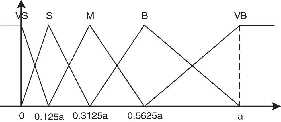
Figure 4: Membership functions of inputs |e|
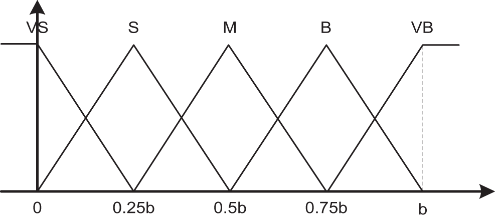
Figure 5: Membership functions of inputs |de|
There are three outputs from the three fuzzy tuners, kp, ki and kd, with the outputs having ranges from 0 to 1. Singleton membership functions are then used for the fuzzy output partitions. Fig. 6 shows five membership functions (VS, S, M, B and VB) corresponding to the five output states (very small, small, medium, big, and very big), respectively.
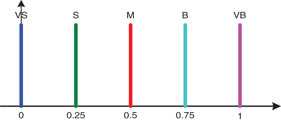
Figure 6: Membership functions of the outputs kp, ki, and kd
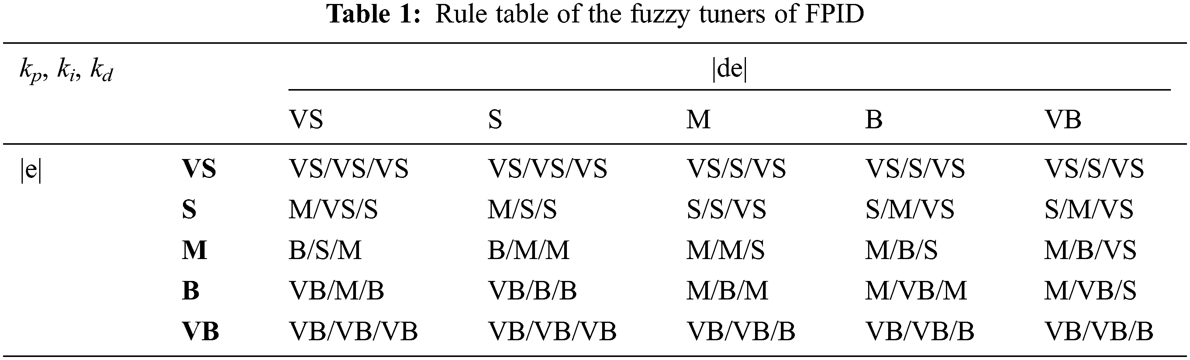
The design rules of the fuzzy tuners are shown in Table 1. The MAX-PROD formula is chosen as the main strategy for the implication process:
where
where
where
2.2.3 Fuzzy Linearization Feedback Control (FLFC) Design
The FLFC is quite similar to FPID design as Section 2.2.2 above. The FLFC is shown in Fig. 7. Here, there are three fuzzy tuners for the three output parameters such as K1, K2 and K3. There are three outputs from the three fuzzy tuners, k1, k2 and k3, with the outputs having ranges from 0 to 1. And finally, these output values of the fuzzy tuners are then substituted into Eq. (30) to compute three parameters, K1, K2 and K3, as follows:
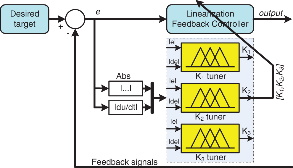
Figure 7: The tuning FLFC diagram
where
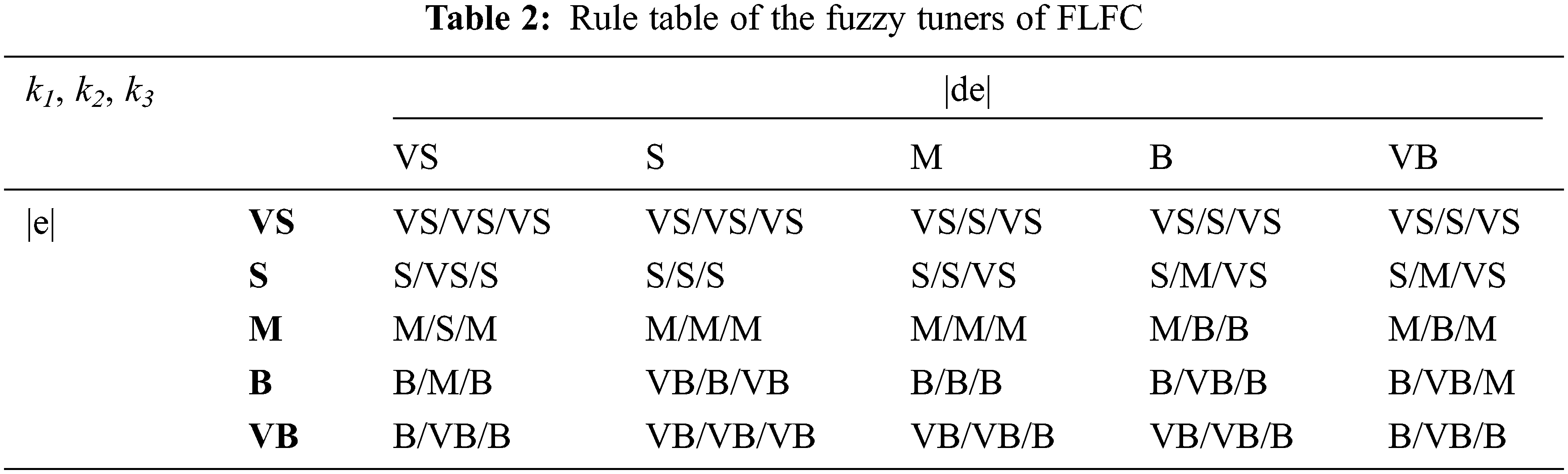
Because of the difference between the LFC and PID controllers, the design rule base of FLFC is also different from that of FPID, as shown in Table 2 below:
In this section, we apply PID and FPID algorithms using the step input to detect overshoot locations where we need to change the signal, as depicted in Fig. 8. According to the experiment, we have KP = 3.80473, KI = 9.26887, and KD = 0.02778. The simulation results show that the FPID algorithm has a lower overshoot than the traditional PID algorithm. Meanwhile, the time to the steady-state of the PID is slightly better but not significantly. Therefore, the combination of fuzzy and PID performs better than the conventional PID controller. In the following Sections, we continue to investigate the performance difference when using LFC and FLFC algorithms.
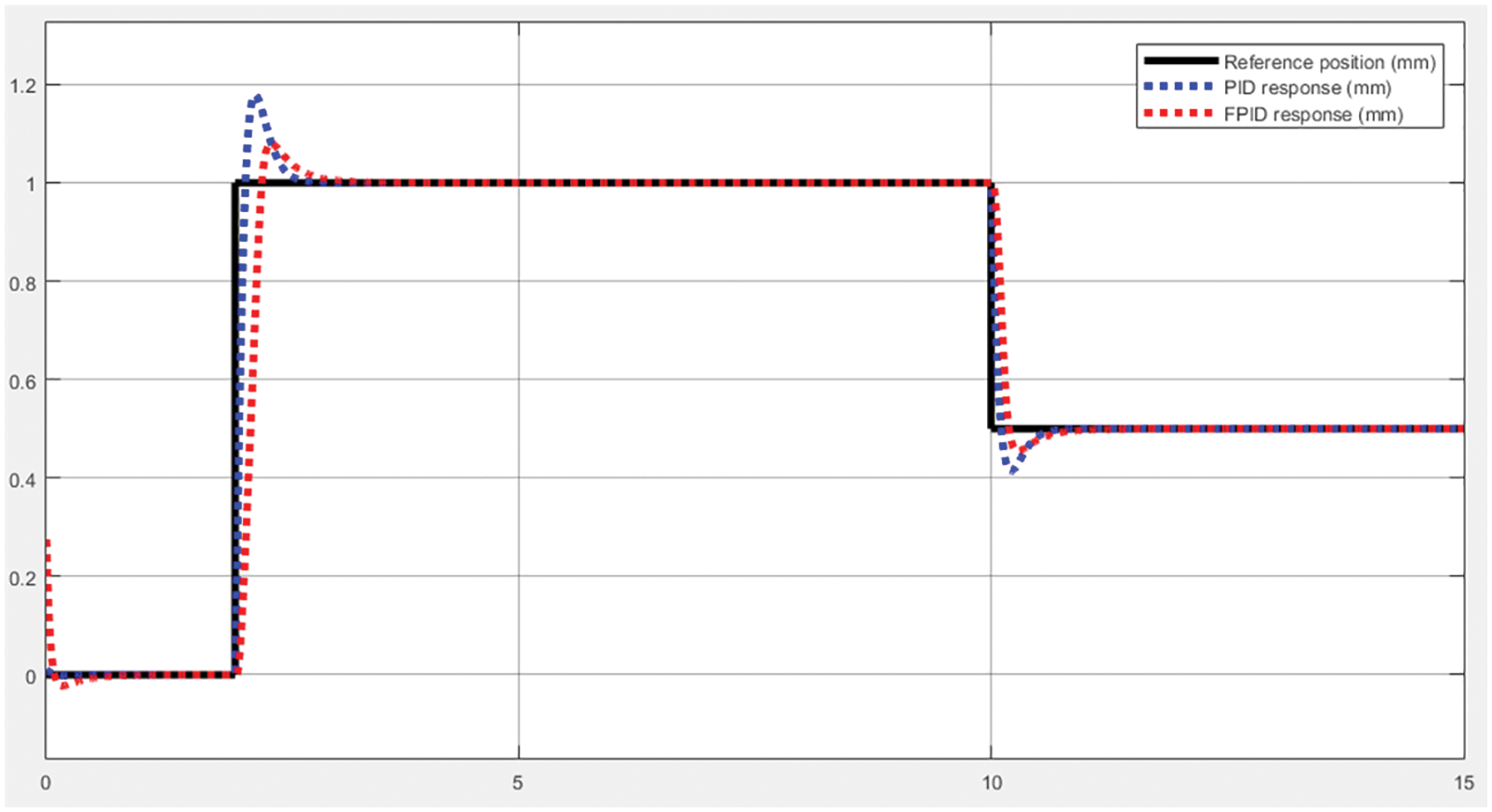
Figure 8: The PID and FPID response
According to the simulation results above, the FPID algorithm is not too superior to the PID algorithm. However, in this case, the LFC controller has shown significant superiority over the PID. The simulation results in Fig. 9 show that the LFC ensures extremely low overshoots and achieves a very fast steady-state.
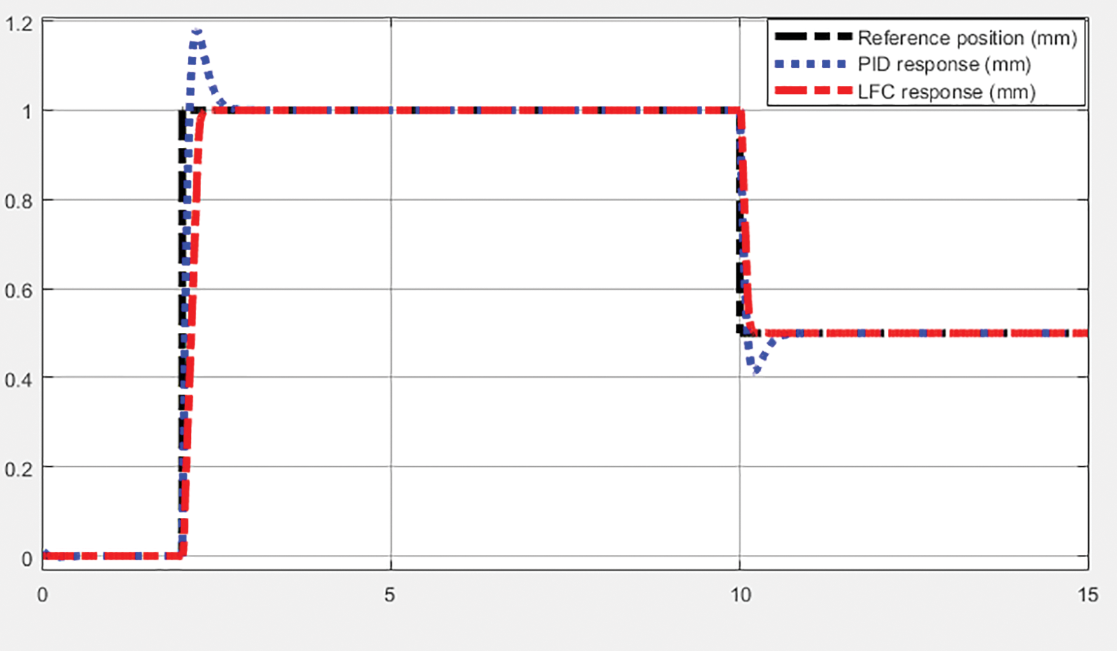
Figure 9: LFC and PID response with step input
In this section, we continue to evaluate the superiority of LFC and FLFC controllers through the same simulation process. The fuzzy tuner parameters are given as: k1 = 90, k2 = 2700, k3 = 27000. The results in Fig. 10 show that the EHA system with the FLFC algorithm achieves a more impressive overshoot and time to steady-state. Thus, in all the experiments performed, the system performance improved in the order of PID, FPID, LFC, and FLFC.
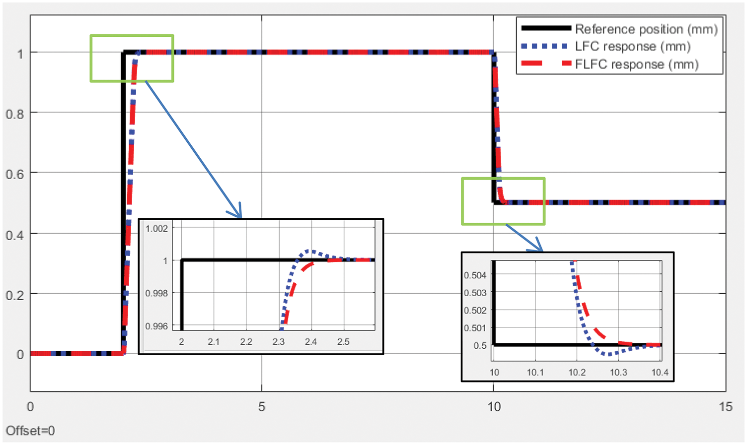
Figure 10: LFC and FLFC response with step input
3.4 Error Performance Evaluation among Controllers
To evaluate the performance among the above controllers, we applied the sinusoidal signal to investigate the maximum error of each controller when the system reaches a steady-state. Fig. 11 proved that the FLFC response signal had the best asymptote to the desired reference signal.
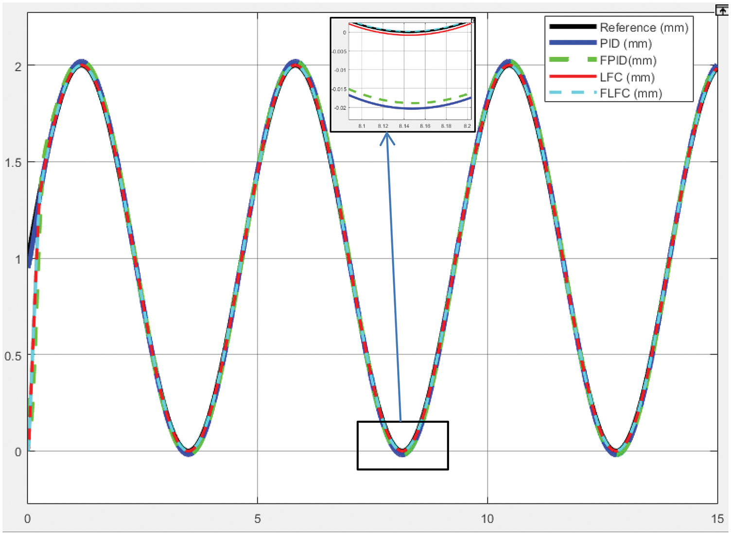
Figure 11: The feedback signals when applying PID, FPID, LFC, and FLFC
To determine the error level of each investigated controller, we presented the errors of the PID and FPID controllers (Fig. 12), LFC, and FLFC (Fig. 13), respectively. The improved algorithms consistently achieved a lower error level than the traditional methods in each case. Specifically, FPID (Fig. 12) and FLFC (Fig. 13) were the controllers that exhibited lower error levels than the PID and LFC controllers. However, to calculate that difference in detail, we proposed to evaluate the controller efficiency through the error performance.
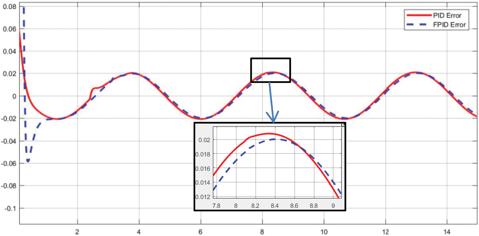
Figure 12: The errors of PID and FPID
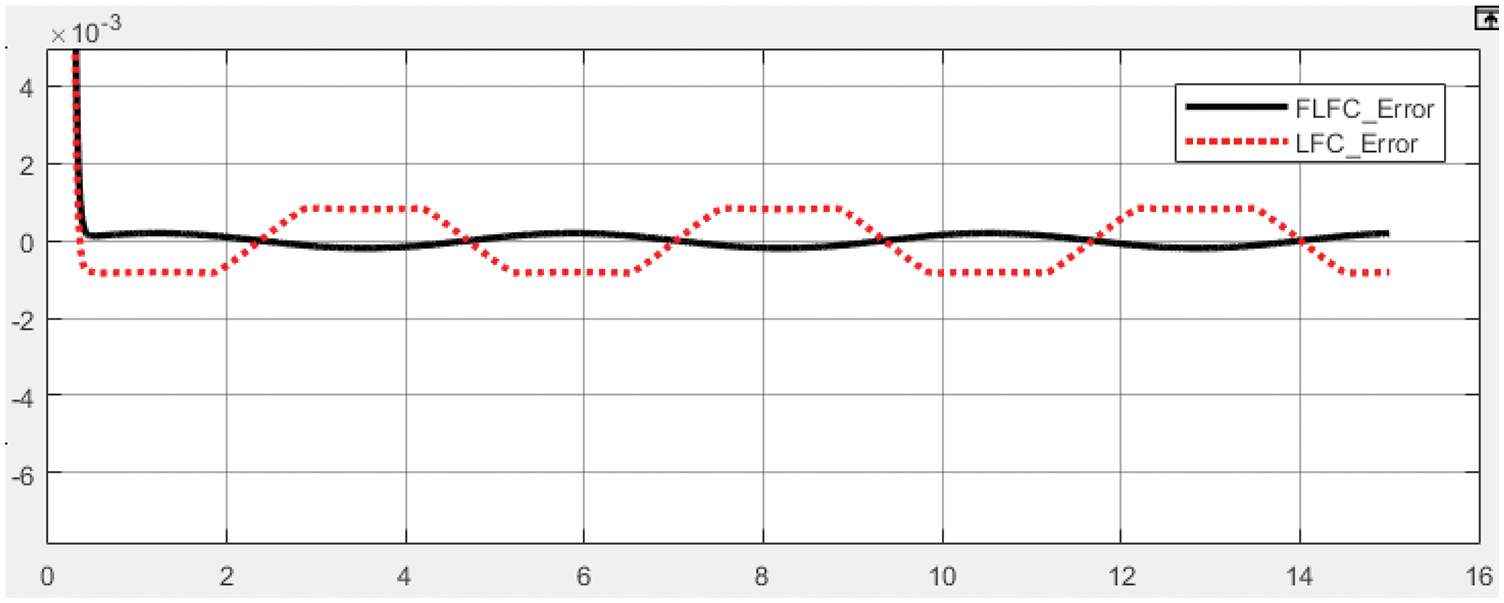
Figure 13: The errors of LFC and FLFC
In this system, we computed error performance 4 cases as follows, and then we obtained the control errors as shown in Table 3. It is worth noting that the PID algorithm has the lowest accuracy, followed by FPID and LFC. Of all the applied algorithms, the FLFC algorithm achieved the best and approximate 99% and 77% accuracy, respectively, compared with the PID and LFC algorithms.
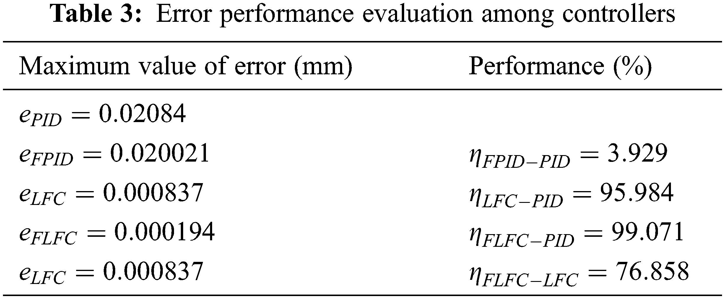
• The performance of the fuzzy logic algorithm compared to the PID controller is given as:
where
• The performance of the feedback controller compared to the PID controller is given as:
• The error performance of the feedback controller compared to the PID controller is given as:
• The performance of the fuzzy logic algorithm compared to the feedback controller is given as:
where
In this paper, we developed the FLFC algorithm based on the combination of fuzzy logic and feedback control to improve the control quality of EHA systems. The simulation results showed that the performance of the proposed algorithm is much higher, and the system’s error has also improved significantly. Thus, the improved algorithm created an essential premise for enhancing the quality of automated systems based on EHA. In the future, we will focus on enhancing the performance of EHA systems in real industrial applications by improving the control algorithm. Combining traditional algorithms and modern control systems is also a promising research direction.
Acknowledgement: This research was supported by Research Foundation funded by Thu Dau Mot University.
Funding Statement: The authors received no specific funding for this study.
Conflicts of Interest: The authors declare that they have no conflicts of interest to report regarding the present study.
References
1. G. Altare and A. Vacca, “A design solution for efficient and compact electro-hydraulic actuators,” Procedia Engineering, vol. 106, no. 2, pp. 8–16, 2015. [Google Scholar]
2. S. Salleh, M. F. Rahmat, S. M. Othman and K. A. Danapalasingam, “Review on modelling and controller design of hydraulic actuator systems,” International Journal on Smart Sensing and Intelligent Systems, vol. 8, no. 1, pp. 338–367, 2015. [Google Scholar]
3. N. Zainab and M. Hammad, “System identification and controller design for hydraulic actuator,” Technology Forces Journal of Engineering and Sciences, vol. 3, no. 2, pp. 11–27, 2021. [Google Scholar]
4. Y. Xia, Y. Nie, Z. Chen, L. Lyu and P. Hu, “Motion control of a hydraulic manipulator with adaptive nonlinear model compensation and comparative experiments,” Machines, vol. 10, no. 3, pp. 214, 2022. [Google Scholar]
5. J. Huang, H. An, Y. Yang, C. Wu, Q. Wei et al., “Model predictive trajectory tracking control of electro-hydraulic actuator in legged robot with multi-scale online estimator,” IEEE Access, vol. 8, pp. 95918–95933, 2020. [Google Scholar]
6. D. Lee, B. Song, S. Y. Park and Y. S. Baek, “Development and control of an electro-hydraulic actuator system for an exoskeleton robot,” Applied Sciences, vol. 9, no. 20, pp. 4295, 2019. [Google Scholar]
7. M. Yang, C. Wang, Z. Qi, X. Wang, H. Yu et al., “Design and model analysis of a robotic joint with circular electro-hydraulic actuator,” in Proc. ICARM, Singapore, Singapore, pp. 520–525, 2018. [Google Scholar]
8. Y. K. Lee and S. J. Lee, “A bio-mimetic robot arm actuated by micro EHA,” in Proc. URAI, Jeju, Korea, pp. 39–44, 2013. [Google Scholar]
9. W. Han, K. T. Chau, Z. Hua and H. Pang, “Compact wireless motor drive using orthogonal bipolar coils for coordinated operation of robotic arms,” IEEE Transactions on Magnetics, vol. 58, no. 2, pp. 1–8, 2022. [Google Scholar]
10. C. Y. Liu, J. J. Liang, T. H. S. Li and K. C. Chang, “Motion imitation and augmentation system for a six degrees of freedom dual-arm robot,” IEEE Access, vol. 7, pp. 153986–153998, 2019. [Google Scholar]
11. A. Gaile and Y. Lue, “Electro hydraulic actuation (EHA) systems for primary flight control, landing gear and other type of actuation,” in Proc. AUS, Beijing, China, pp. 723–728, 2016. [Google Scholar]
12. R. Ding, M. Cheng, L. Jiang and G. Hu, “Active fault-tolerant control for electro-hydraulic systems with an independent metering valve against valve faults,” IEEE Transactions on Industrial Electronics, vol. 68, no. 8, pp. 7221–7232, 2021. [Google Scholar]
13. Y. Liu, L. Tian, Z. Li and W. Zhang, “Fault modelling of electro hydraulic actuator in gas turbine control system based on Matlab/Simulink,” in Proc. CCDC, Kunming, China, pp. 2086–2091, 2021. [Google Scholar]
14. H. Li, Y. Huang, G. Zhu and Z. Lou, “Adaptive LQT valve timing control for an electro-hydraulic variable valve actuator,” IEEE Transactions on Control Systems Technology, vol. 27, no. 5, pp. 2182–2194, 2019. [Google Scholar]
15. S. A. Ali, A. Christen, S. Begg and N. Langlois, “Continuous-discrete time-observer design for state and disturbance estimation of electro-hydraulic actuator systems,” IEEE Transactions on Industrial Electronics, vol. 63, no. 7, pp. 4314–4324, 2016. [Google Scholar]
16. R. K. Gupta, L. Kumar and N. P. Mandal, “Displacement control of an electro-hydraulic actuator using proportional solenoid valve,” in Proc. GUCON, New Delhi, India, pp. 673–677, 2019. [Google Scholar]
17. W. Lee and W. K. Chung, “Disturbance-observer-based compliance control of electro-hydraulic actuators with backdrivability,” IEEE Robotics and Automation Letters, vol. 4, no. 2, pp. 1722–1729, 2019. [Google Scholar]
18. X. Tian, H. An, Z. Zhang, X. Chang, H. Ma et al., “Force tracking control for electro-hydraulic actuators based on radial basis function neural networks,” in Proc. RCAR, Xining, China, pp. 572–577, 2021. [Google Scholar]
19. D. Won, W. Kim and M. Tomizuka, “Nonlinear control with high-gain extended state observer for position tracking of electro-hydraulic systems,” IEEE/ASME Transactions on Mechatronics, vol. 25, no. 6, pp. 2610–2621, 2020. [Google Scholar]
20. T. V. Nguyen and C. Ha, “Sensor fault-tolerant control design for mini motion package electro-hydraulic actuator,” Processes, vol. 7, no. 2, pp. 89, 2019. [Google Scholar]
21. T. V. Nguyen and C. Ha, “Experimental study of sensor fault-tolerant control for an electro-hydraulic actuator based on a robust nonlinear observer,” Energies, vol. 12, no. 22, pp. 4337, 2019. [Google Scholar]
22. M. G. Skarpetis and F. N. Koumboulis, “Robust PID controller for electro—hydraulic actuators,” in Proc. ETFA, Cagliari, Italy, pp. 1–5, 2013. [Google Scholar]
23. C. M. Shern, R. Ghazali, C. S. Horng, C. Soon and H. I. Jaafar, “Optimization techniques in PID controller on a nonlinear electro-hydraulic actuator system,” Journal of Advanced Research in Fluid Mechanics and Thermal Sciences, vol. 56, no. 2, pp. 296–303, 2020. [Google Scholar]
24. M. Tajjudin, N. Ishak, H. Ismail, M. H. F. Rahiman and R. Adnan, “Optimized PID control using Nelder-Mead method for electro-hydraulic actuator systems,” in Proc. ICSGRC, Shah Alam, Malaysia, pp. 90–93, 2011. [Google Scholar]
25. N. Ishak, M. Tajjudin, R. Adnan, H. Ismail and Y. M. Sam, “Real-time application of self-tuning PID in electro-hydraulic actuator,” in Proc. ICCSCE, Penang, Malaysia, pp. 364–368, 2011. [Google Scholar]
26. R. Adnan, M. Tajjudin, N. Ishak, H. Ismail and M. H. F. Rahiman, “Self-tuning fuzzy PID controller for electro-hydraulic cylinder,” in Proc. CSPA, Penang, Malaysia, pp. 395–398, 2011. [Google Scholar]
27. M. E. M. Essa, M. A. S. Aboelela, M. A. Moustafa Hassan and S. M. Abdraboo, “Fractional order fuzzy logic position and force control of experimental electro-hydraulic servo system,” in Proc. MOCAST, Thessaloniki, Greece, pp. 1–4, 2019. [Google Scholar]
28. H. D. Choi and S. H. You, “Fuzzy finite memory state estimation for electro-hydraulic active suspension systems,” IEEE Access, vol. 9, pp. 99364–99373, 2021. [Google Scholar]
29. K. Ormandzhiev and S. Yordanov, “Neuro-fuzzy control synthesis for electro-hydraulic follow-up system,” in Proc. ELMA, Varna, BULGARIA, pp. 1–6, 2019. [Google Scholar]
30. P. J. Costa Branco and J. A. Dente, “On using fuzzy logic to integrate learning mechanisms in an electro-hydraulic system. I. Actuator’s fuzzy modelling,” IEEE Transactions on Systems, Man, and Cybernetics, Part C (Applications and Reviews), vol. 30, no. 3, pp. 305–316, 2000. [Google Scholar]
31. Z. Haifeng, X. Jian, G. Wenliang and Z. Li, “Modeling and simulation of EHA system based on fuzzy adaptive PID control,” in Proc. ITOEC, Chongqing, China, pp. 750–753, 2017. [Google Scholar]
32. D. M. Wonohadidjojo, G. Kothapalli and M. Y. Hassan, “Position control of electro-hydraulic actuator system using fuzzy logic controller optimized by particle swarm optimization,” International Journal of Automation and Computing, vol. 10, no. 3, pp. 181–193, 2013. [Google Scholar]
33. X. H. Ha, C. Ha and J. Lee, “Fuzzy vector field orientation feedback control-based slip compensation for trajectory tracking control of a four track wheel skid-steered mobile robot,” International Journal of Advanced Robotic Systems, vol. 10, no. 4, pp. 15, 2013. [Google Scholar]
34. D. S. Vanaja, A. A. Stonier and A. Moghassemi, “A novel control topology for grid-integration with modular multilevel inverter,” International Transactions on Electrical Energy Systems, vol. 31, no. 12, 2021. https://onlinelibrary.wiley.com/doi/epdf/10.1002/2050-7038.13261. [Google Scholar]
35. Y. Song, Z. Hu and C. Ai, “Fuzzy compensation and load disturbance adaptive control strategy for electro-h servo pump control system,” Electronics, vol. 11, no. 7, pp. 1159, 2022. [Google Scholar]
36. D. Rodriguez-Guevara, A. Favela-Contreras, F. Beltran-Carbajal, C. Sotelo and D. Sotelo, “An MPC-LQR-LPV controller with quadratic stability conditions for a nonlinear half-car active suspension system with electro-hydraulic actuators,” Machines, vol. 10, no. 2, pp. 137, 2022. [Google Scholar]
Cite This Article
 Copyright © 2023 The Author(s). Published by Tech Science Press.
This work is licensed under a Creative Commons Attribution 4.0 International License , which permits unrestricted use, distribution, and reproduction in any medium, provided the original work is properly cited.
 Downloads
 Citation Tools