
 Submit a Paper
 Propose a Special lssue
 Open Access
ARTICLE

Cognitive Granular-Based Path Planning and Tracking for Intelligent Vehicle with Multi-Segment Bezier Curve Stitching
1 Chongqing Key Laboratory of Manufacturing Equipment Mechanism Design and Control, Chongqing Technology and Business University, Chongqing, 400067, China
2 National Research Base of Intelligent Manufacturing Service, Chongqing Technology and Business University, Chongqing, 400067, China
3 Department of Electrical Electronics and Telecommunications Engineering, University of Cuenca, Cuenca, Ecuador
* Corresponding Author: Huiyan Zhang. Email:
Intelligent Automation & Soft Computing 2023, 37(1), 385-400. https://doi.org/10.32604/iasc.2023.036633
Received 07 October 2022; Accepted 22 December 2022; Issue published 29 April 2023
 View Full Text
 Download PDF
Abstract
Unmanned vehicles are currently facing many difficulties and challenges in improving safety performance when running in complex urban road traffic environments, such as low intelligence and poor comfort performance in the driving process. The real-time performance of vehicles and the comfort requirements of passengers in path planning and tracking control of unmanned vehicles have attracted more and more attentions. In this paper, in order to improve the real-time performance of the autonomous vehicle planning module and the comfort requirements of passengers that a local granular-based path planning method and tracking control based on multi-segment Bezier curve splicing and model predictive control theory are proposed. Especially, the maximum trajectory curvature satisfying ride comfort is regarded as an important constraint condition, and the corresponding curvature threshold is utilized to calculate the control points of Bezier curve. By using low-order interpolation curve splicing, the planning computation is reduced, and the real-time performance of planning is improved, compared with one-segment curve fitting method. Furthermore, the comfort performance of the planned path is reflected intuitively by the curvature information of the path. Finally, the effectiveness of the proposed control method is verified by the co-simulation platform built by MATLAB/Simulink and Carsim. The simulation results show that the path tracking effect of multi-segment Bezier curve fitting is better than that of high-order curve planning in terms of real-time performance and comfort.Keywords
With the rapid development of internet and communication technology, the traditional automobile begins to develop towards the direction of network and automation. Full automation of cars, i.e., unmanned vehicles are expected to become a reality in the future. Leading the transformation of automotive industry is of great significance to socio-economic development. Path planning and tracking control are core issues in the field of autonomous vehicle research, and their performance directly affects the execution effect of autonomous driving behavior. An integrated longitudinal and transverse trajectory tracking control method based on nonlinear Model Predictive Control (MPC) has been proposed in [1], which improved the tracking accuracy through the effective combination of nonlinear MPC and obstacle function method. Guo et al. [2] developed a neural ergonomics-based lateral control model for vehicles by integrating MPC algorithm and arm muscle model on the basis of a neural ergonomics cognitive architecture. The intelligent driving path tracking controller has been designed based on the model prediction principle in [3], and the cost function and constraints conditions of the controller have been designed according to the data clustering results. For the optimal control problem, Chen et al. [4] proposed the constrained iterative linear quadratic regulator method. This method is suitable for nonlinear dynamical systems with constraints. Bae et al. [5] provided a feasible real-time path planning and tracking method for autonomous vehicles based on fifth-order Bezier curves, however, the overall real-time performance of the system needs to be improved. Feng et al. [6] proposed a vector field histogram search method, which combined with Bezier curve as the reference line, selected the optimal trajectory points and searched collision-free states. Many scholars have made great contributions in the field of path planning and control of unmanned vehicles, but there are still some deficiencies in practical applications.
For unmanned vehicles, driving safety is the top priority [7], so the path planning and control module plays a decisive role in driving safety. For example, a control block based on a super-twisting second-order sliding mode controller has been investigated in [8] for steering of a quadcopter Unmanned Aerial Vehicle (UAV) to achieve the desired position and attitude. At the same time, unmanned vehicles need to meet the comfort requirements of passengers. Therefore, this paper focuses on a local path planning and tracking method based on multi-segment Bezier curve stitching and MPC theory. By using low-order interpolation curve splicing, the planning computation cost can be reduced, and the real-time performance of planning can be improved. By arranging the position of the relevant control points of Bezier curve reasonably, the constraint of the planned path on the comfort level can be achieved. Finally, the algorithm is verified by the co-simulation platform.
In addition, the piecewise fitting method proposed in this paper can accurately fit the global path, and the fitting error can be controlled within the allowable range. The traditional fitting method often has the following problems when facing the complex road environment: First of all, when low-order curves are used for fitting, they will not be able to fit a reasonable driving path for unmanned vehicles, which will result in planning failure. Second, when the higher-order curve is used for fitting, the computation amount of planning module will be greatly increased, which will result in the real-time performance of planning is poor. The method proposed in this paper can solve these two problems effectively.
Fig. 1 shows the different effects of the global path fitted by multi-segment low-order Bezier curve and a one-segment high-order Bezier curve. It can be seen that the path accuracy of multi-segment splicing fitting is obviously better than that of a one-segment high-order curve. In terms of real-time performance, the multi-segment low-order Bezier curve stitching approach also outperforms one-segment high-order curve fitting, which will be verified in detail later.
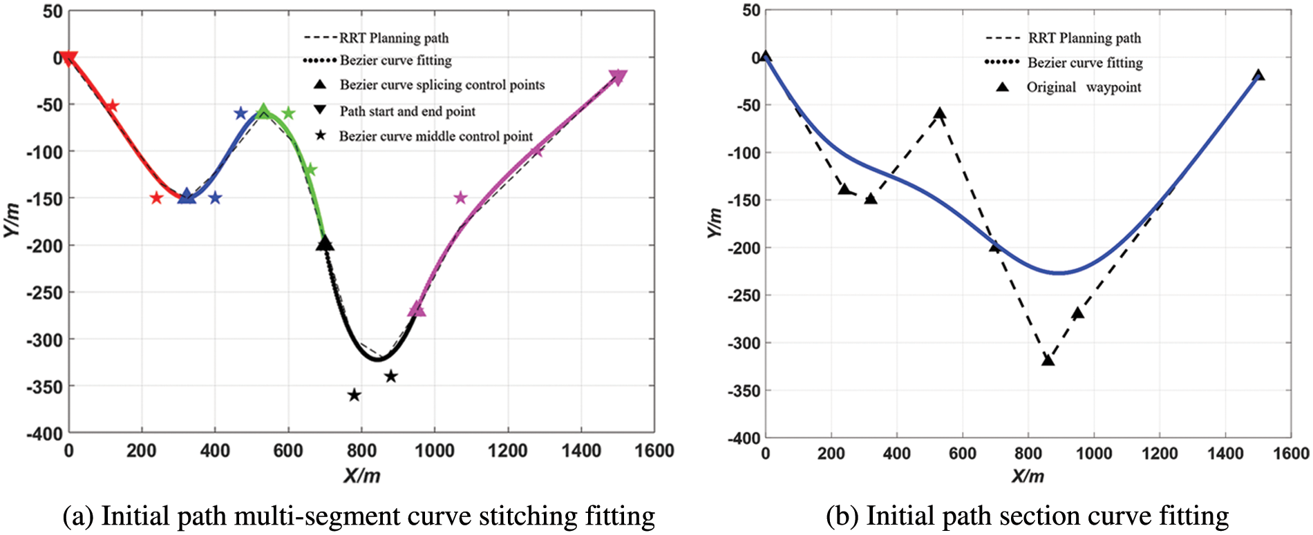
Figure 1: Initial path curve fitting
In this paper, a multi-segment Bezier curve fitting path planning and tracking control method based on MPC is proposed. The fitting method of multi-segment low-order curve splicing reduces the calculation amount of planning module and improves the real-time performance. At the same time, in this paper, the comfort performance of planned path is reflected intuitively by the curvature information. Finally, the co-simulation platform is used to verify the effectiveness of the algorithm.
The construction of vehicle dynamics or kinematics model is of great significance to planning and tracking of unmanned vehicles. The vehicle dynamics model can be used to predict the motion of vehicles over time and generate the optimal trajectory satisfying various geometric and safety constraints in advance, which can improve the feasibility of planning process to a certain extent. To make path planning algorithm works efficiently when facing complex traffic environments, it is necessary to simplify the dynamics model [9,10].
In this section, the motion is considered in three directions: lateral, longitudinal and transverse. Namely, a vehicle transverse dynamics model based on three-degree-of-freedom is developed, and the slip between tires and ground is considered. Compared with kinematics model, the dynamics model can better simulate force situation of vehicles in the process of driving, and more in line with the actual situation of vehicles in the process of high-speed driving. During the modeling process, the following ideal assumptions should be made: (1) The influence of aerodynamics on vehicle’s motion state should be ignored to reduce the complexity of algorithm and improve the efficiency. (2) A small angle assumption should be made for the front wheel deflection angle
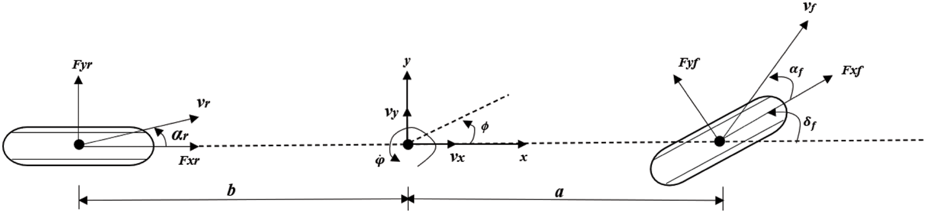
Figure 2: Vehicle dynamics model
A force analysis of the vehicle is carried out in the following equation:
where m is the vehicle mass;
The longitudinal forces exerted on the front and rear tires are:
where
where
Combining Eqs. (1) to (4), the vehicle yaw dynamics model considering tire slip rate can be obtained, whose expression is:
The construction of the dynamics model lays a foundation for the determination of the subsequent MPC controller [11]. In this system, the state is chosen as
3 Motion Planning and Tracking Control
In this paper, Bezier curve will be used for trajectory fitting in the stage of path planning. There are two main reasons for this: First, all the control points of Bezier curve are connected in turn to form a convex polygon which contains the Bezier curve. This property is used to ensure that there is no collision between the planned path and obstacles. Secondly, the first and last control points of Bezier curve are the starting and ending point of the whole curve respectively, the first and last edges of the characteristic polygon are tangent lines of the starting and ending point respectively. This property is of great significance for the smooth connection of each segment of Bezier curves.
The calculation cost of path planner will increase as the order of the Bezier curve increases. In order to solve the problem of numerical stability and computational efficiency [12], this paper adopts low-order Bezier curve stitching fitting method for trajectory planning. Theoretically, this method can greatly improve the performance of path planner, which is the core problem to be studied in this paper.
The specific mathematical formula of Bezier curve is given as follows:
where
The continuity of path concatenation is of great significance for unmanned vehicle systems. The continuity of parametric curves can be divided into two types: parametric continuity and geometric continuity, which are denoted as
For mobile robots (unmanned vehicles belong to high-speed mobile robots), they generally have a minimum rotation radius or speed constraint, requiring the curvature of the tracked path to be less than maximum turning curvature of the robot. Therefore, the geometric continuity of piecewise splicing fitting path becomes very important for path planning of unmanned vehicles.
To achieve a smooth transition of entire trajectory, the following conditions should be met when Bezier curves of two adjacent segments are at the splice: (1) The position is continuous, and the end point P2 of the former segment curve is required to coincide with the beginning point Q0 of the latter segment. (2) Tangential vectors are continuous, requiring points P1, P2(Q0) and Q1 are coincident. (3) Continuity of curvature, which requires two adjacent curves satisfy the continuity of position and tangent vector when all control points are coplanar. In order to simplify the planning algorithm, these two Bezier curves are assumed to be symmetric [13]. As shown in Fig. 3, after the location information of obstacle is clarified, the obstacle position will be set as the first control point of the first Bezier curve For the Bezier curve will not pass through the control point, namely, the obstacle is avoided.
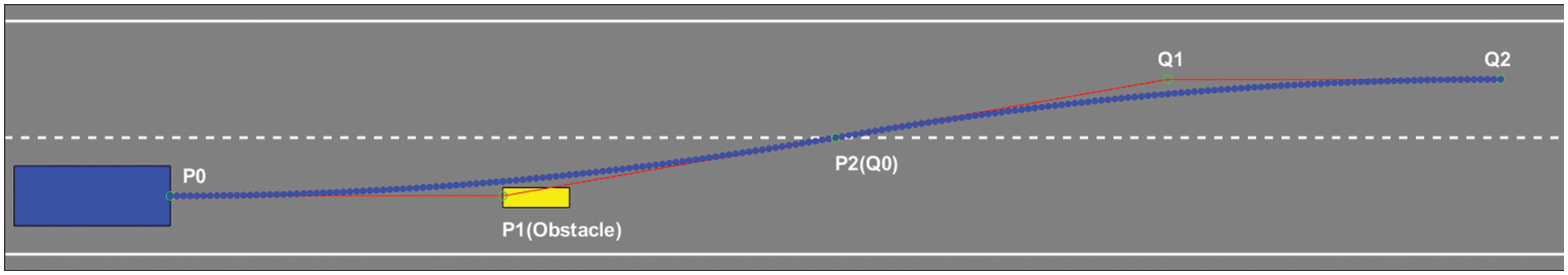
Figure 3: Bezier curves stitching process
The curvature expression for each point on Bezier curve is shown as below. First, the expression of Bezier curve in Eq. (6) is transformed into the form with respect to its transverse coordinates x and longitudinal coordinates y. Then the curvature of each point on Bezier curve is calculated through the following expression in Eq. (8).
In this paper, the perception module of unmanned vehicle is not considered, i.e., the position information of obstacles is known. To meet the requirement of the initial position state of the vehicle, let the first control point be P0 (0,−D/2). And the position information of the obstacle P1 is known, noted as (a,−D/2), the position of the control point P2 is set as (c, 0). Where D is the width of the road and is set as 4 m. The curvature of the whole planned trajectory is determined by the horizontal coordinate c of the control point P2:
Let
Guo et al. [14] systematically introduced various factors that affect vehicle comfort in the process of lanes change. In the present stage, unmanned vehicles focus more on how to realize the automation rather than the intelligence. Passengers’ comfort requirements are an important indicator to evaluate how similar the process of autonomous driving is to that of human driving. In this paper, the curvature of the planned path is associated with lateral acceleration that generated by the vehicle, and the comfort of vehicle driving process is taken as an important constraint in the process of path planning. In order to meet the comfort requirements of passengers, the lateral acceleration during the vehicle driving process is often less than or equal to 0.05 g:
Equivalent to
The horizontal coordinates c of the control point P2(Q0) can be obtained by Eq. (10), which is
Since these two Bezier curves are symmetric, the transverse coordinates of control points Q1 and Q2 can be obtained by symmetry property:
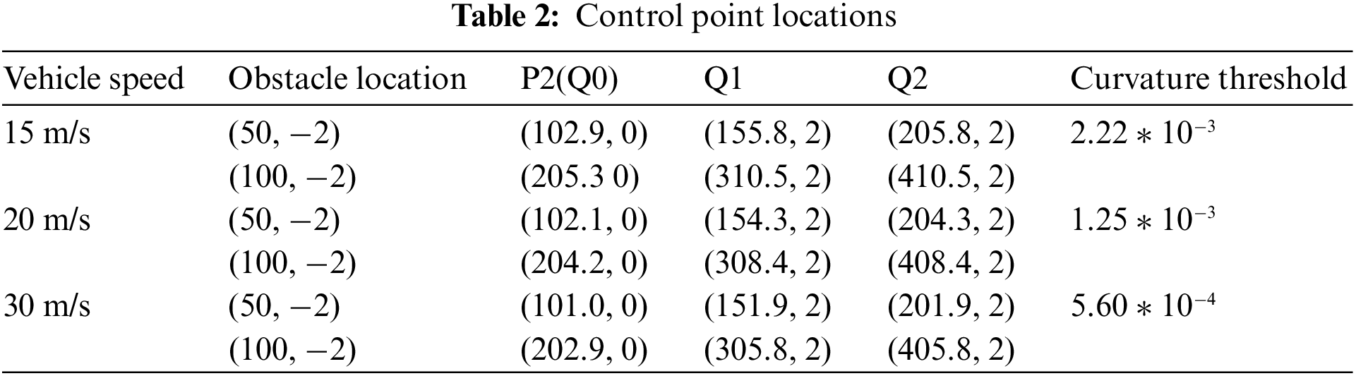
For different vehicle driving conditions, by setting different speed v and combining with Eq. (12), the maximum trajectory curvature K satisfying passenger ride comfort can be obtained. Then, by using the horizontal coordinate information of obstacle a and applying Eq. (10), the transverse coordinate c of the control point P2(Q0) can be obtained. The maximum curvature calculated by Eq. (12) is used as the curvature threshold that meets the comfort condition. The location data of specific control points calculated by MATLAB are shown in Table 2.
The control points of Bezier curve are properly configured to ensure the global continuity and curvature continuity of splicing path. In this way, the unmanned vehicle can effectively track the planned path [15]. The multiple low-order Bezier curve stitching method reduces the complexity of planning module, the real-time performance of planning module is improved.
By selecting several typical working conditions and using Eq. (8), the curvature of planned path is calculated by MATLAB, and the curvature value of complete path at each point is obtained, as shown in Fig. 4.
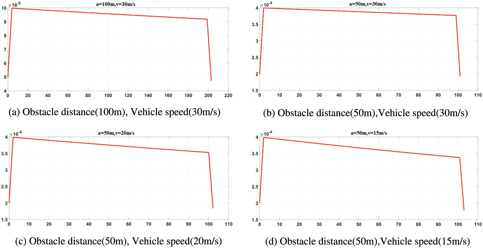
Figure 4: The trajectory of curvature
According to Table 2, the curvature threshold that satisfies passenger riding comfort can be obtained. Curvature information of paths under different driving conditions is shown in Fig. 4. As you can see from the pictures, the curvature of vehicle when avoiding obstacles is lower than the curvature threshold that satisfies the comfort requirements. However, when the speed is high and the obstacle is close to initial position of the vehicle, as shown in Fig. 5 (obstacle a = 50 m, v = 30 m/s), the transverse acceleration of the vehicle will become huge, and the curvature of planned path will exceed the curvature threshold, which cannot meet the requirements of passenger ride comfort. Therefore, this situation should be avoided during the whole driving process.
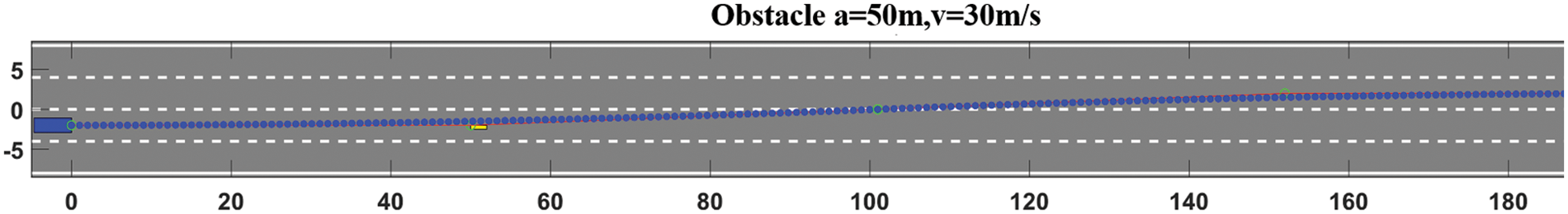
Figure 5: The trajectory when a = 50 m, v = 30 m/s
In terms of computational speed, the multi-segment low-order Bezier curve splicing method adopted in this paper is also improved compared with traditional one-segment high-order curve fitting method. To verify this issue, the simulation speed of curve stitching planning method proposed in this paper will be compared with that of traditional one-stage curve planning method. The computer used in this paper has an Intel Core i5-10400 processor with a 2.90 HGZ CPU.
In the simulation experiment, the path planning time of two second-order Bezier curves was compared with that of a fourth-order Bezier curve. The two planning methods were tested 1000 times under different conditions, taking the average time of path generation as the final time. Specific data can be obtained through simulation experiments, as shown in Table 3.
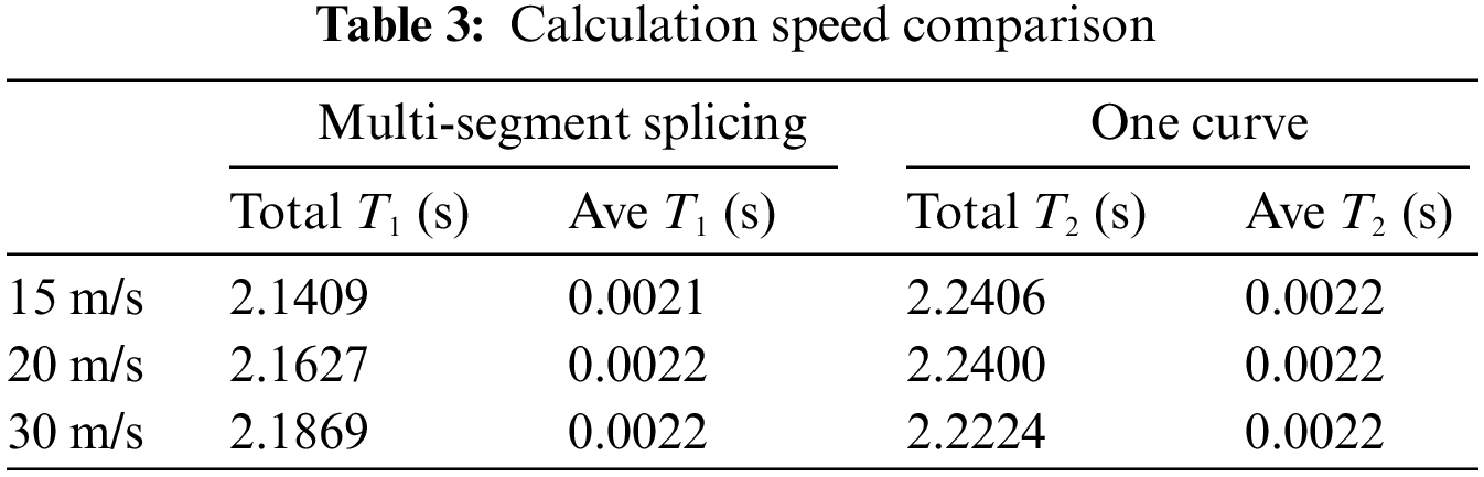
It can be seen from the data in Table 3 that the calculation time of path planning with multi-segment stitching is slightly higher than that with one-segment stitching of the curve. As the actual operating conditions of unmanned vehicles are very complex, the calculation cost will increase dramatically, so the gap in computation time between the multi-segment splicing fitting method and the one-segment curve fitting method will be enlarged. Therefore, the use of multi-segment stitching has a certain effect on improving the real-time performance.
3.2 Model Predictive Controller Design
The basic idea of model predictive control (MPC) is to predict the future output of system by using the established mathematical model, the current state of system and the future control of system. The system control objectives with constraints are solved by multiple iterations [16]. The whole process is shown in Fig. 6.
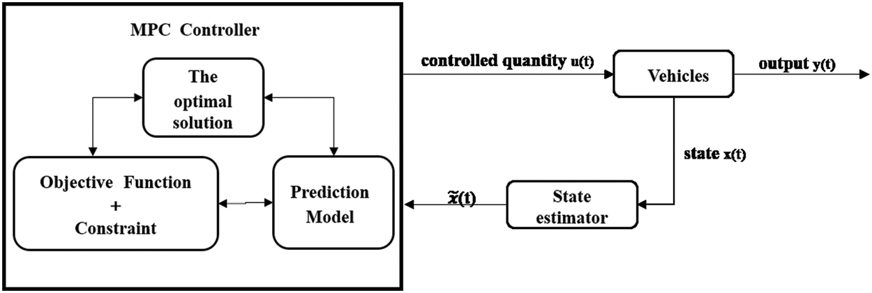
Figure 6: MPC schematic diagram
Eq. (5) shows a three-degree-of-freedom vehicle yaw nonlinear dynamics model
where
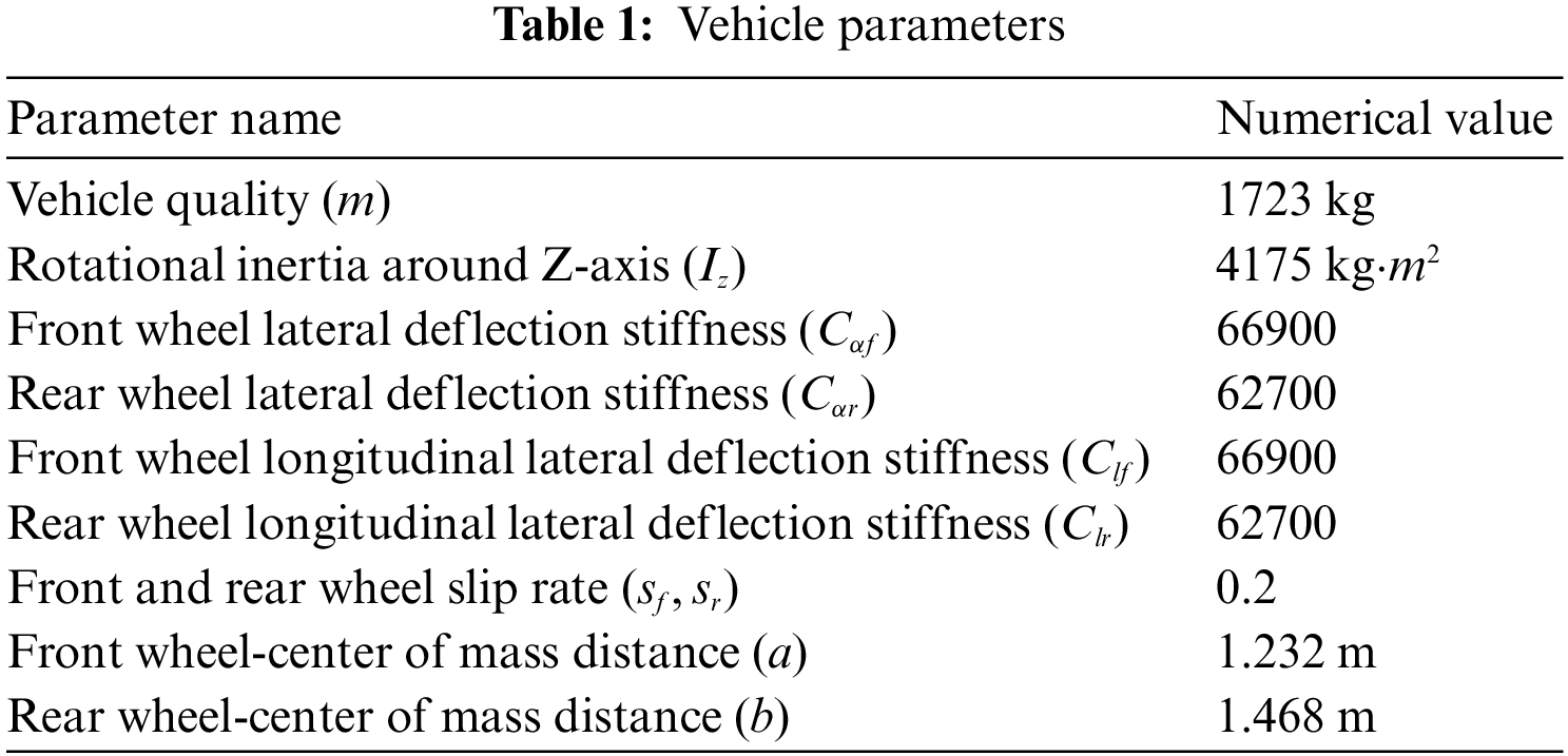
Relevant parameters in the above equation are shown in Table 1.
The desired system response characteristics should have the following two characteristics:
(1) For the state vector, the tracking deviation should be able to converge to zero quickly and smoothly, and finally remain balanced.
(2) For the control vector, the control input should be as small as possible.
This type of problem is a typical multi-objective optimal control problem. Therefore, the weighted sum of cumulative tracking deviation and accumulated control input generated in the tracking process can be constructed as an objective function, which is expressed in the following formula:
where Q is positive definite state weighting matrix; R is positive definite control weighting matrix;
After designing the objective function, the next step is to set the corresponding constraints. In the design process of the controller, the control limit constraints and the control increment limit constraints will be main object to be considered in the control process [19], and their expressions are given as follows:
where
Combining the above objective function and the relevant constraints, the whole control model can be expressed as following:
where
The first term of the control increment is extracted, and the optimal control is obtained by applying the expression
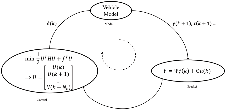
Figure 7: Flow chart of MPC design
To make the experimental results more clear and more intuitive, Carsim and MATLAB/Simulink are used to build a co-simulation platform. Fig. 8 shows the simulation example of MPC based on the vehicle dynamics model. In this co-simulation, Carsim is responsible for providing the vehicle dynamics model and setting up the input and output ports, Simulink is mainly responsible for building the overall structure of controller and implementing the planning control module through the S-Function.

Figure 8: Co-simulation platform
4.1 Trajectory Tracking and Obstacle Avoidance Performance Analysis
In the simulation process, different simulation conditions are set to analyze the performance of the controller. Obstacles are set to be located at 50 and 100 m in front of the car, and the car avoid the obstacle at different speeds of 15, 20 and 30 m/s, respectively. Tracking and obstacle avoidance performances are tested by simulation, and the simulation results are shown in Fig. 9.
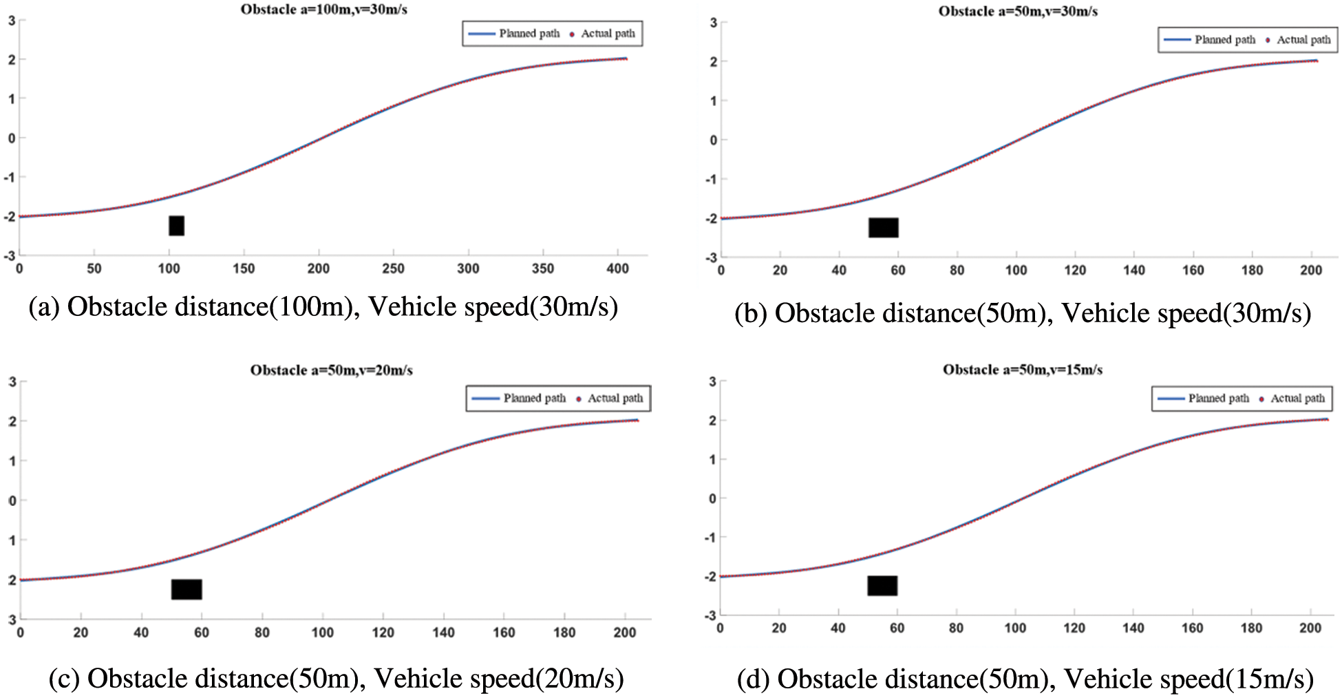
Figure 9: The diagram of trajectory tracking
As can be seen from the tracking results, the actual tracking path of the vehicle fits closely with the planned path no matter the vehicle is driving at a low-speed or a high-speed. The tracking effect is acceptable. At the same time, the vehicle can effectively avoid the obstacle. The stability and effectiveness of the proposed controller based on MPC meet the expected requirement.
4.2 Comfort Performance Analysis
The lateral acceleration can be obtained by the curvature information of the path, which is the main index that affects the comfort requirements of passengers. In the path planning stage, curvature constraint conditions are considered in advance to ensure the control accuracy and reduce the restrictions in the control stage. Relevant data show that passengers will feel uncomfortable during the driving, when the lateral acceleration is greater than 0.05 g. In this paper, several typical working conditions were selected for comfort performance analysis, and the lateral acceleration of the vehicle during driving process was extracted to compare with the threshold value of 0.05 g. By this way, it is clear to evaluate the comfort of the path which planned by the planner. The simulation results are shown in Fig. 10.
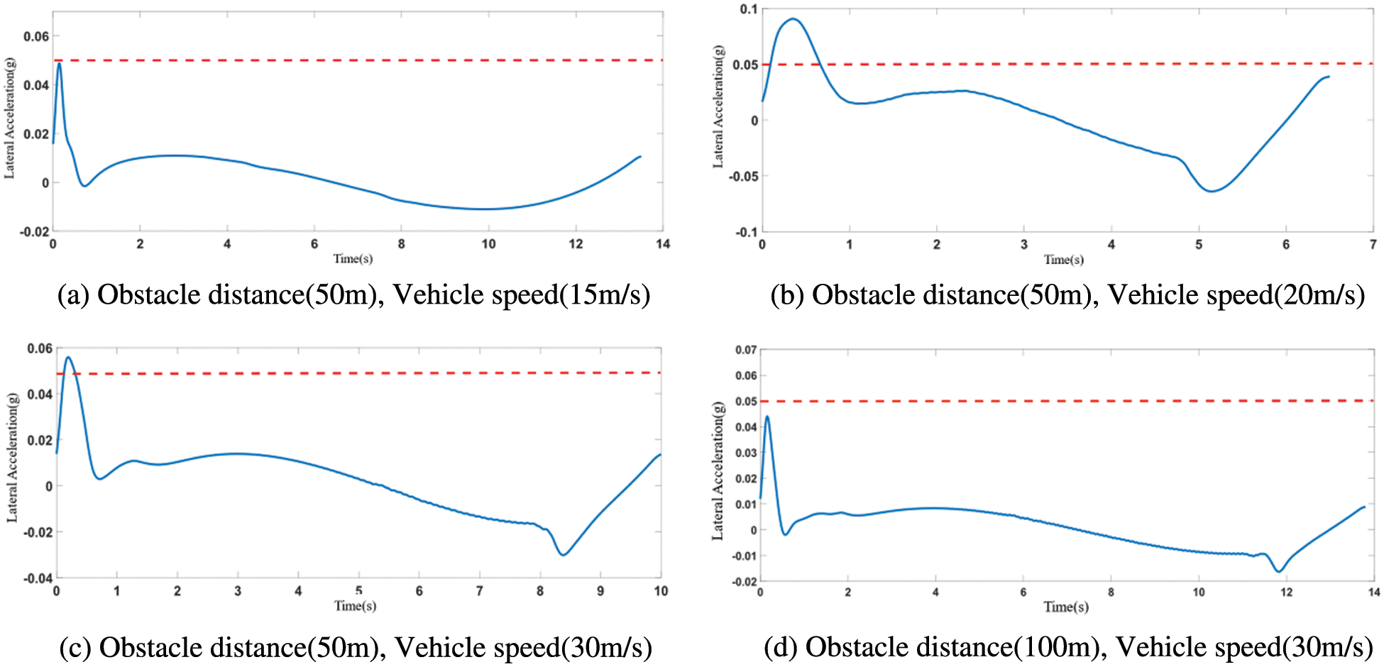
Figure 10: The diagram of lateral acceleration
It can be seen from the lateral acceleration reflected in Fig. 10a, when the vehicle avoids the obstacle at a low speed, that is, when v = 15 m/s, the lateral acceleration of the vehicle is less than the threshold value of 0.05 g, the lateral acceleration of the vehicle is relatively gentle during the whole driving process, which can meet the comfort requirements of passengers. As shown in Fig. 10b, when the speed of the vehicle reaches 20 m/s, the lateral acceleration exceeds the corresponding threshold value at the initial stage of driving, that is, 0–1 s, but the maintenance time is short and the lateral acceleration exceeds the amount within the error allowed. The reason for this is that the front wheel angle changes in a short period of time, leading to a large lateral force due to the initial high speed of the vehicle. In order to avoid this situation, the corresponding constraint conditions can be set in the controller. As shown in Fig. 10c, when the speed of vehicle reaches 30 m/s, due to the obstacle located 50 m in front of the vehicle, the vehicle will avoid the close-distance obstacle at a high speed. As a result, a large lateral acceleration will be generated in the process of avoiding obstacle, which will seriously affect the passenger’s riding experience. When the obstacle is placed 100 m in front of the vehicle and the obstacle is avoided at the same speed, the driving path meets the requirements of riding comfort, which conforms to the objective law, as shown in Fig. 10d. Therefore, in the actual driving process, the occurrence of such working conditions with higher speed should be avoided, in order to ensure the safety of passengers and drivers.
In the planning layer, this paper implements the path planning process of unmanned vehicles based on low-order Bezier curves and multi-segmented splicing. In the control layer, a tracking controller is designed based on the MPC theory to achieve accurate tracking of the planned path. Especially, the maximum path curvature which satisfies ride comfort is regarded as an important constraint condition, and the corresponding curvature threshold is used to calculate control points of Bezier curve, so as to achieve the requirement of path comfort. Simulation results show that the proposed path planning method has advantages of small computation cost and high real-time performance and can also be applied to the trajectory planning of UAVs to improve the ability of obstacle avoidance. In addition, for automated guided vehicle material trolley which does not need to consider ride comfort, the flexibility of material trolley can be improved by using the proposed planning method.
In practical engineering applications, with the increase of constraints, the computation cost of the MPC will also increase, thus affecting the real-time performance of vehicles. How to simplify the vehicle model and optimize the MPC algorithm to maximize the efficiency of the controller are the focus of future work.
Funding Statement: : This work was supported by the National Natural Science Foundation of China (62003062), Chongqing Natural Science Foundation Project (Grant No. cstc2020jcyj-msxmX0803, cstc2020jcyj-msxmX0077), Chongqing Municipal Education Commission Scientific Research Project (Grant No. KJQN202100824) and Chongqing Technology and Business University Postgraduate Innovative Scientific Research Project (Grant No. yjscxx2021-122-44).
Conflicts of Interest: : The authors declare that they have no conflicts of interest in reporting regarding the present study.
References
1. L. Chen, K. Zhou, Y. F. Cai, C. L. Teng, Q. X. Sun et al., “Longitudinal and lateral comprehensive trajectory tracking control of intelligent vehicles based on NMPC,” Journal of Automotive Engineering, vol. 43, pp. 153–161, 2021. [Google Scholar]
2. Y. S. Guo, H. J. Zhang, R. Fu and C. Chang, “Research on intelligent vehicle lateral control model based on neuro-ergonomics,” Journal of Automotive Engineering, vol. 43, pp. 1057–1065, 2021. [Google Scholar]
3. Z. Y. Zhang, K. Long, R. H. Du and C. X. Huang, “Trajectory tracking coordinated control for autonomous vehicle in high-speed overtaking,” Journal of Automotive Engineering, vol. 43, pp. 995–1004, 2021. [Google Scholar]
4. J. Chen, W. Zhan and M. Tomizuka, “Autonomous driving motion planning with constrained iterative LQR,” IEEE Transactions on Intelligent Vehicles, vol. 4, no. 2, pp. 244–254, 2019. [Google Scholar]
5. I. Bae, J. Moon, H. Park, J. H. Kim and S. Kim, “Path generation and tracking based on a Bezier curve for a steering rate controller of autonomous vehicles,” in Proc. of 16th Int. IEEE Conf. on Intelligent Transportation Systems (ITSC 2013), Hague, Netherlands, pp. 436–441, 2013. [Google Scholar]
6. Y. Feng, J. Yang, C. Ma and H. J. Rong, “Combing VFH with Bezier for motion planning of an autonomous vehicle,” in Proc. of 2nd Annual Int. Conf. on Information System and Artificial Intelligence, Tianjin, China, 887, 2017. [Google Scholar]
7. Y. Lai, Y. Chen and J. Perng, “Sensor fusion of camera and MMW radar based on machine learning for vehicles,” International Journal of Innovative Computing, Information and Control, vol. 18, no. 1, pp. 271–287, 2022. [Google Scholar]
8. D. Matouk, F. Abdessemed, O. Gherouat and Y. Terchi, “Second-order sliding mode for position and attitude tracking control of quadcopter UAV: Super-twisting algorithm,” International Journal of Innovative Computing, Information and Control, vol. 16, no. 1, pp. 29–43, 2020. [Google Scholar]
9. W. Li, H. Zhou, W. Xu, X. Wang and W. Pedrycz, “Interval dominance-based feature selection for interval-valued ordered data,” IEEE Transactions on Neural Networks and Learning Systems, 2022. https://doi.org/10.1109/TNNLS.2022.3184120 [Google Scholar] [PubMed] [CrossRef]
10. W. Li, S. Zhai, W. Xu, W. Pedrycz, Y. Qian et al., “Feature selection approach based on improved Fuzzy C-Means with principle of refined justifiable granularity,” IEEE Transactions on Fuzzy Systems, 2022. https://doi.org/10.1109/TFUZZ.2022.3217377 [Google Scholar] [CrossRef]
11. J. Gong, Y. Jiang and W. Xu, Model predictive control for self-driving vehicles [M]. Beijing: Beijing Institute of Technology Press, 2020. [Google Scholar]
12. C. Cheng, Y. Q. He, C. G. Bu and J. D. Han, “Quartic Bezier curve based trajectory generation for autonomous vehicles with curvature and velocity constraints,” Journal of Acta Automatica Sinica, vol. 41, pp. 486–496, 2015. [Google Scholar]
13. J. Chen, P. Zhao, T. Mei and H. Liang, “Lane change path planning based on piecewise Bezier curve for autonomous vehicle,” in Proc. of 2013 IEEE Int. Conf. on Vehicular Electronics and Safety, Dongguan, China, pp. 17–22, 2013. [Google Scholar]
14. Y. S. Guo, Y. Q. Su, R. Fu and W. Yuan, “Research on the influence of lane-changing maneuvers on passenger comfort,” China Journal of Highway and Transport, vol. 35, no. 5, pp. 221–230, 2022. [Google Scholar]
15. H. Li, Y. Luo and J. Wu, “Collision-Free path planning for intelligent vehicles based on Bezier curve,” IEEE Access, vol. 7, pp. 123334–123340, (S2169–35362019. [Google Scholar]
16. Z. H. You, Research on Model Predictive Control-Based Trajectory Tracking for Unmanned Vehicles. Jilin: Jilin University, 2018. [Google Scholar]
17. I. Bae, J. H. Kim, J. Moon and S. Kim, “Lane change maneuver based on Bezier curve providing comfort experience for autonomous vehicle users,” in Proc. of 2019 IEEE Intelligent Transportation Systems Conf. (ITSC), Auckland, New Zealand, pp. 2272–2277, 2019. [Google Scholar]
18. H. Y. Chen, J. W. Gong and G. M. Xiong, Introduction to self-driving car [M]. Beijing: Beijing Institute of Technology Press, 2014. [Google Scholar]
19. T. Zhan, S. Ma, W. Li and W. Pedrycz, “Exponential stability of fractional order switched systems with mode-dependent impulses and its application,” IEEE Transactions on Cybernetics, vol. 52, no. 11, pp. 11516–11525, 2022. [Google Scholar] [PubMed]
20. C. Y. Yang, K. Chen and L. Peng, “Design of obstacle avoidance tracker for unmanned vehicle based on model predictive control,” Journal of Hubei University of Automotive Technology, vol. 34, pp. 11–15, 2020. [Google Scholar]
Cite This Article
 Copyright © 2023 The Author(s). Published by Tech Science Press.
This work is licensed under a Creative Commons Attribution 4.0 International License , which permits unrestricted use, distribution, and reproduction in any medium, provided the original work is properly cited.
 Downloads
 Citation Tools