
 Submit a Paper
 Propose a Special lssue
 Open Access
ARTICLE
Mechanical Properties of Self-Compacting Rubberized Concrete with Different Rubber Types under Triaxial Compression
1 College of Civil Engineering and Architecture, Guangxi University, Nanning, 530004, China
2 College of Civil Engineering and Architecture, Nanning University, Nanning, 541699, China
* Corresponding Authors: Weishu Fu. Email: ; Jianzeng Shen. Email:
(This article belongs to the Special Issue: Sustainable Concrete with Recyclable Materials)
Journal of Renewable Materials 2023, 11(2), 581-598. https://doi.org/10.32604/jrm.2022.022074
Received 19 February 2022; Accepted 12 May 2022; Issue published 22 September 2022
 View Full Text
 Download PDF
Abstract
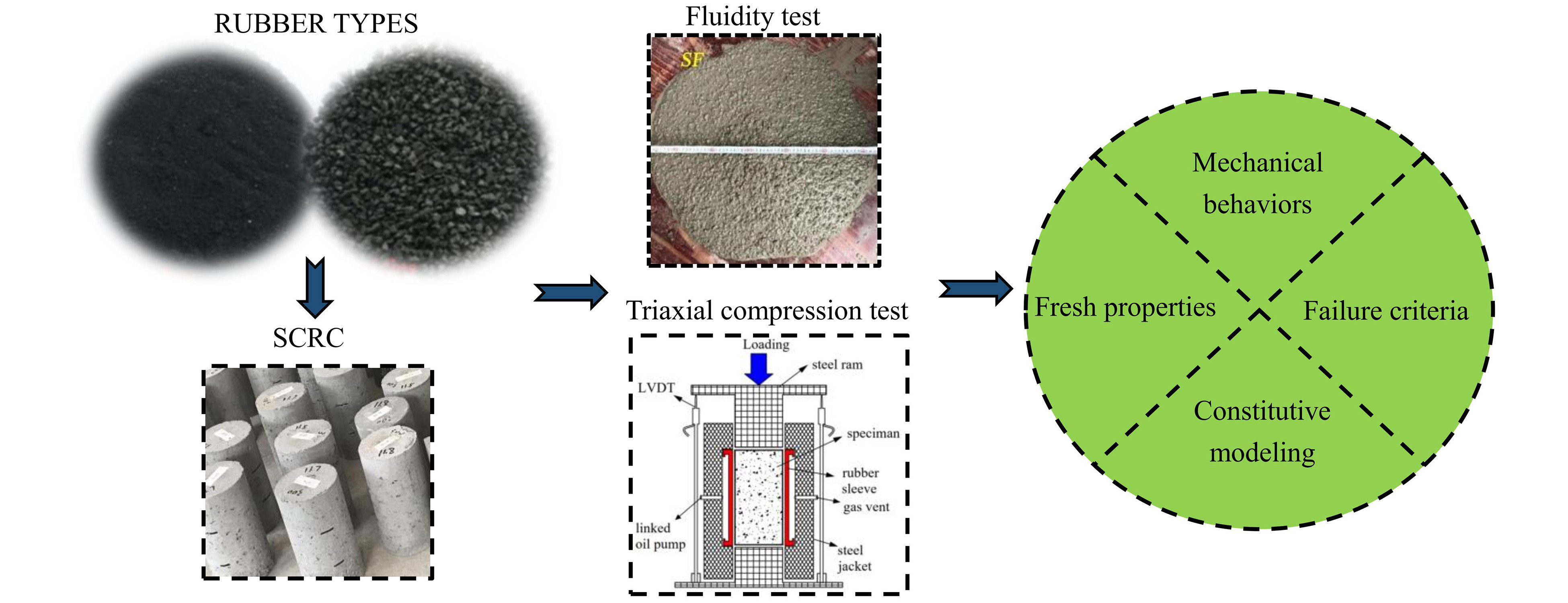
Different rubber aggregates lead to changes in the effect of stress conditions on the mechanical behavior of concrete, and studies on the triaxial properties of self-compacting rubber concrete (SCRC) are rare. In this study, 35 cylindrical specimens taking lateral stress and rubber type as variables were prepared to study the fresh properties and mechanical behaviors of SCRC under triaxial compression, where the rubber contains two types, i.e., 380 μm rubber powder and 1–4 mm rubber particles, and four contents, i.e., 10%, 20% and 30%. The test results demonstrated that SCRC exhibited a typical oblique shear failure mode under triaxial compression and had a more moderate descending branch compared with self-compacting concrete (SCC). The presence of lateral stress can significantly improve the compression properties, including initial elastic modulus, peak stress and peak strain, with an improvement range of 3%–73% for peak stress. While rubber aggregates mainly targeted the deformation abilities and toughness for improvement, and the peak strain improvement ranges were 0.1–3.1 times and 0.1–1.0 times for SCRC containing rubber powder and SCRC containing rubber particles, respectively, relative to SCC. At a high lateral stress of at least 12 MPa, the loss of strength due to the addition of rubber can be controlled within 10%, in which case the content of rubber powder and rubber particles was recommended to be at most 20% and 30%, respectively. Based on the Mohr-Coulomb theory, the failure criteria of SCRC with different rubber types were established. For analysis and design purposes, an empirical model was proposed to predict the stress-strain behavior under triaxial compression, considering the influence of different rubber content and lateral stress. The results obtained in this study can provide a valuable reference for the design and application of self-compacting rubberized concrete in practical projects, especially those involving three-way compression states and requiring high-quality deformation and energy dissipation.Graphic Abstract
Keywords
Nomenclature
| SCRC | Self-compacting rubberized concrete |
| SCC | Self-compacting concrete |
| SCRC-A | Self-compacting rubberized concrete containing rubber powder |
| SCRC-B | Self-compacting rubberized concrete containing rubber particles |
| a | Control parameters in Guo model |
| b | Control parameters in Guo model |
| c | Cohesion in Mohr-Coulomb theory |
| d1 | Maximum circular spreading diameter of concrete in slump flow test |
| d2 | Diameter of concrete circle at an angle perpendicular to d1 |
| f0 | Peak stress in the uniaxial compression test |
| r | Rubber content |
| SF | Slump flow |
| S1 | Area enclosed by the stress-strain curve before the peak |
| S1 + S2 | Area enclosed by the stress-strain curve before the stress drops to 80% of the peak |
| T500 | Time required for concrete to reach a diameter of 500 mm |
| σ | Compressive stress |
| σcc | Peak stress in the triaxial compression test |
| σw | Lateral stress |
| ε | Compressive strain |
| εcc | Peak strain in the triaxial compression test |
| ε0 | Peak strain in the uniaxial compression test |
| γ | Ratio of the peak stress of SCRC to SCC |
| η | Ratio of the peak strain of SCRC to SCC |
| λ | Fitting parameter in Mohr-Coulomb theory |
| μ | Fitting parameter in Mohr-Coulomb theory |
Rapid industrialization has caused many environmental problems [1,2], such as resource shortage, dramatic increase in carbon emissions, and solid waste accumulation. The popularization of the concept of carbon neutrality has promoted researchers in various fields to make efforts to solve the above problems. In the field of civil engineering, scholars not only use recycled aggregates to prepare concrete [3] to alleviate the shortage of natural aggregates, but also use blast furnace slag to replace cement to reduce the impact of industrial by-products and carbon dioxide emissions on the natural environment [4,5]. However, almost half of the discarded tires, as one of the major industrial solid wastes, are directly landfilled or piled up, which runs counter to the green development of human society [6]. Therefore, it has been proposed that crushed rubber can be mixed into concrete to form a new civil engineering material, i.e., rubberized concrete.
Relevant studies have shown that rubberized concrete has some performance advantages. Khaloo et al. [7] and Zheng et al. [8] reported that the incorporation of rubber enhanced the toughness of concrete. Thomas et al. [9] found that compared to ordinary concrete, rubberized concrete had better abrasion resistance due to the abrasion-resistant effect of rubber particles at the interface, and the abrasion depth decreased with increasing rubber content. Based on the free vibration research, Xue et al. [10] and Zheng et al. [11] found that the damping coefficient of rubberized concrete was higher than that of ordinary concrete, and the corresponding seismic energy dissipation capacity was higher. However, it is undeniable that the bond strength between the rubber and cement paste is lower [9,12,13], leading to a decrease in strength of the rubberized concrete. Also, due to the existence of gaps between the rubber and cement paste, the durability properties of rubberized concrete are reduced [14], including carbonization, sulfate attack, and resistance to chloride ion penetration [14–17]. Thence, scholars have attempted to improve the compactness and strength loss of rubberized concrete.
In order to improve the compactness, scholars suggested combining rubber with self-compacting concrete (SCC) [18] to take advantage of its ability to flow and compact under self-weight alone. In this regard, studies by Najim et al. [19–21] mentioned that the compactness and performance of SCC were better than ordinary concrete. In addition, the combination of rubber and SCC can effectively avoid rubber floating caused by external vibration, thereby ensuring the effective performance of rubberized concrete. With the aim to reduce the strength loss, some scholars proposed the chemical method of rubber pre-soaking [22,23], which significantly improved the bonding properties between the rubber and cement paste. On the other hand, some scholars have also effectively compensated the strength loss by the physical method of applying restraint, e.g., FRP or steel pipe restraints [24,25]. The latter of these methods is commonly used for structural solutions in practical engineering and is also more conducive to the multidirectional stress conditions to which the material is subjected internally.
Unfortunately, studies on the mechanical properties of rubberized concrete have mainly focused on uniaxial compression properties and simple rubber concrete materials [21], while triaxial properties for self-compacting rubberized concrete (SCRC) are rare. Gholampour et al. [26] only explored the effect of rubber content on the triaxial mechanical properties of rubberized concrete but failed to address the type of rubber and the stress-strain constitutive relation of rubberized concrete under triaxial constraints, which is a missing but important theoretical guidance. In fact, triaxial compression behavior differs significantly from conventional uniaxial behavior, which depends on the different combination of concrete aggregate type and content [27,28]. Furthermore, although many constitutive models for constrained concrete have been proposed, most of them are applicable to reinforced concrete. In the absence of studies on the triaxial performance of rubberized concrete, the applicability of existing constitutive models needs to be verified.
To this end, conventional triaxial tests were conducted on SCRC to investigate its mechanical properties more comprehensively by analyzing the interaction effects of lateral stress, rubber type and content, and to establish triaxial compression failure criterion and stress-strain constitutive model considering variables.
2.1 Raw Materials and Mix Proportions
The ordinary Portland cement with a compressive strength of 42.5 MPa was used to prepare the mixture as per the Chinese standard “Common Portland Cement” (GB 175-2007) [29]. In order to prepare qualified SCC and SCRC, two additives were added. One was Fly Ash (FA) consisting of spherical particles with a smooth and dense surface to provide a ball-like delivery of aggregates in the concrete mixture. Another admixture was a polycarboxylic acid high-performance water plasticizer with a water reducing rate of 30.5%, which can improve the workability of the mixture. The chemical and physical properties of cement and FA are shown in Table 1. In accordance with the Chinese standard “Pebble and crushed stone for construction” (GB/T14685-2011) [30], crushed stone aggregate with a dimension of 5–20 mm was used as coarse aggregates, and the natural river sand with a fineness modulus of 2.6 was used as fine aggregate. Two types of rubber, i.e., powder in 380 μm and particle in 1–4 mm, were selected. Table 2 and Fig. 1 show the physical properties of aggregates.


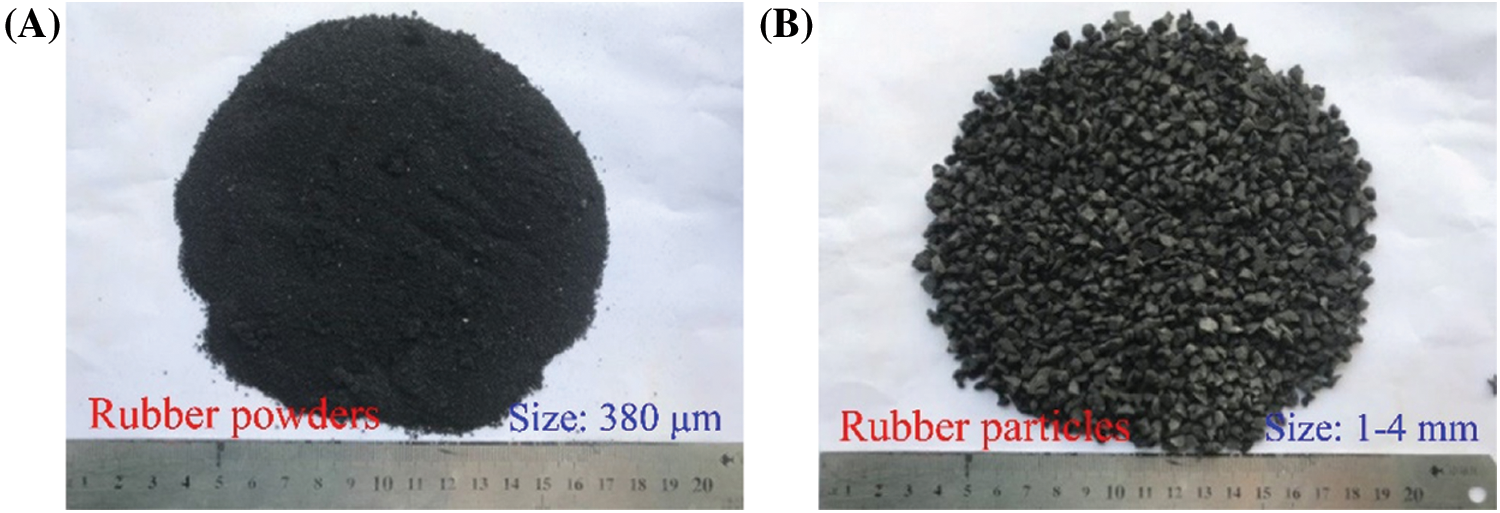
Figure 1: The types of rubber aggregates
The purpose of this paper was to study the effect of rubber aggregates on the performance of SCRC under the condition that natural sand was replaced by equal volume. Therefore, the proportions of cementitious, water, Plasticizer and crushed stone were kept constant except for rubber and natural sand as per the Chinese standard “Technical specification for application of self-compacting concrete” (JGJ/T 283-2012) [31] and “Specification for mix proportion design of ordinary concrete”’ (JGJ 55-2011) [32]. Accordingly, the water-to-binder ratio (W/B) was set to 0.41. The proportions of sand (SP) were 0.46, 0.43, 0.40, and 0.37 for rubber content of 0%, 10%, 20%, and 30% in SCRC, respectively. More details about the mixing proportion are presented in Table 3.

2.2 Specimen Preparation and Test Methods
In order to evaluate the uniformity and workability of SCRC, each series of concrete mixtures was sampled three times for slump flow (SF) and slump flow time (T500) testing in accordance with the Chinese standard JGJ/T 283-2012 [31]. After wetting the inner wall of the slump cylinder, fresh SCRC was poured into the cylinder using a funnel. Subsequently, the slump cylinder was lifted vertically to allow free flow of SCRC. As shown in Fig. 2, the time for the fresh SCRC to reach a diameter of 500 mm was recorded as T500, and the final spreading diameters, e.g., d1 and d2, were measured to obtain SF based on Eq. (1).
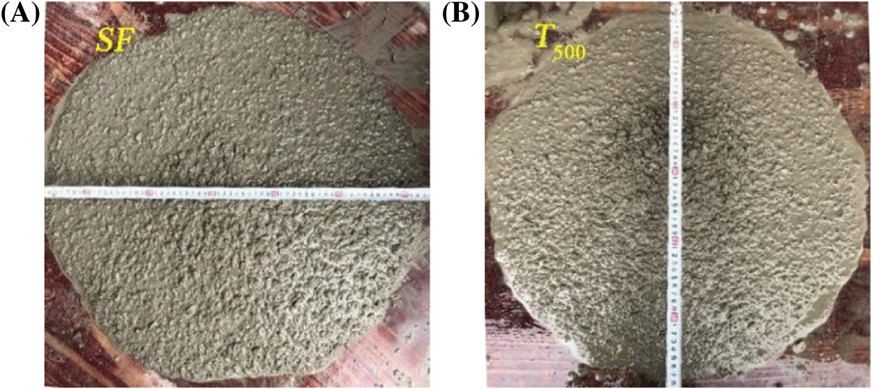
Figure 2: Measurement of SF (A) and T500 (B)
where d1 is the maximum circular spreading diameter of concrete in slump flow test, and d2 is the diameter of concrete circle at an angle perpendicular to d1.
2.2.2 Triaxial Compression Test
For each series of concrete mixtures, five cylindrical specimens with dimensions of Ф100 mm × 200 mm were cast for triaxial compression tests. After setting for 24 h, the specimens were demoulded and then water cured for 7 days. The specimens were then placed in a curing chamber at a temperature of 20 ± 2°C and a relative humidity of more than 95% for 28 days. Before testing, the ends of the specimens were smoothed and made parallel, and then the surfaces were oiled to reduce the friction between the specimens and the rubber sleeve as well as the restraining effect of the ends.
A 1500-kN RMT-201 rock testing device was used to carry out a triaxial compression test as per the Chinese standard “Standard for test methods of engineering rock mass” (GB/T 50266-2013) [33]. As shown in Fig. 3A, the gap between the rubber sleeve and steel jacket was filled with oil to apply lateral stresses (including 0, 3, 6, 9, and 12 MPa). The vertical displacements were transmitted to the specimen by a steel ram. Besides, the load and axial deformations were recorded by the computer and LVDTs, respectively. For the uniaxial compression case, the specimens were tested with displacement control at a rate of 0.02 mm/s until failure. For the triaxial compression case, the vertical force was loaded by a hybrid force-displacement control, as shown in Fig. 3B. The vertical load was first controlled by force, which increased in equal proportion to the lateral stress until a predetermined value of lateral stress was reached. Then, the lateral stress state was kept constant, and the vertical load was switched to displacement control with a constant loading rate of 0.02 mm/s until the specimen failed.
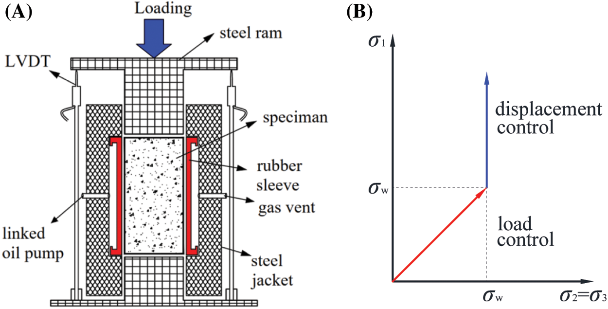
Figure 3: Illustration of the triaxial compressive test method. (A) Loading device. (B) Loading rules
During the above specimen preparation, an additional specimen was reserved for scanning electron microscopy (SEM) observation for each series of SCRC. Likewise, one sample for each series of SCRC that had been damaged was withdrawn for observation. Cubes with the size of 10 mm × 10 mm × 10 mm were cut from the middle of the specimen, soaked and cleaned with alcohol solution and dried in a vacuum desiccator for 24 h. Then the surface was polished using sandpaper and coated with a layer of platinum.
3.1 Fresh Properties and Microstructure
As shown in Fig. 4, SF and T500 were affected by the variables in an opposite pattern. The effect of rubber types was weak, while the increase of rubber content caused a decrease of SF and increase of T500, which implied a decrease in flow properties. The reason for this is that the rough surface of the rubber leads to increased friction between the aggregates and increased plastic viscosity of the mixture.
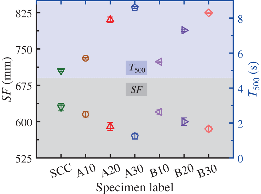
Figure 4: Results of SF and T500
As shown in Fig. 5, the structure between rubber and cement matrix is loose, and there are more air voids and micro cracks, especially for SCRC-A. Since rubber is a hydrophobic material, not only its bond with cement mortar is not easy to produce, but also the hydration products of cementitious materials are difficult to adsorb on the surface of rubber. Therefore, the bonding performance between rubber and cement mortar is poor, and the point can easily become a weak area in the process of force.
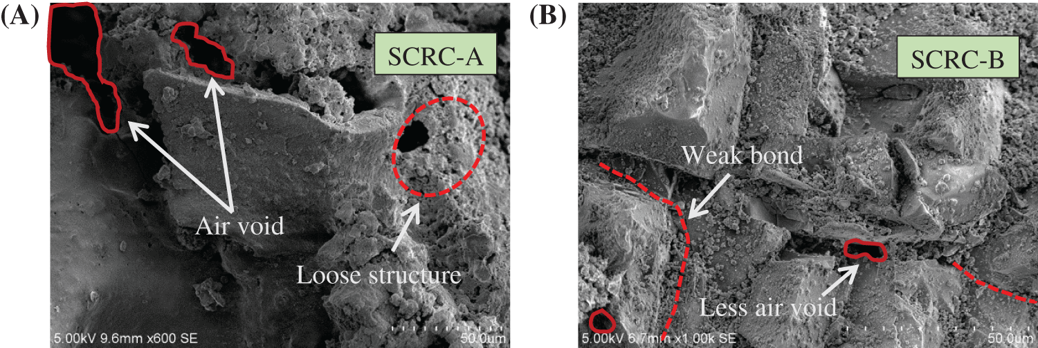
Figure 5: SEM images of SCRC before testing
3.2 Failure Mode under Triaxial Compression
In this experiment, the authors found that lateral stress is a vital factor in influencing the failure modes in comparison with rubber types and content. So, typical failure modes of SCC and SCRC under different lateral stress are shown in Fig. 6. Both SCC and SCRC presented longitudinal splitting failure under uniaxial compression and the specimens were kept intact. When the lateral stress (σw) reached 3 MPa, diagonal cracks (e.g., Figs. 6C~6J) appeared on the surface of the specimens. The reason is that the presence of the lateral restraint force strengthens the biaxial strength of the material and forces the crack development path to tend to the oblique weak region. When the lateral stress exceeded 6 MPa, the cracks showed a failure mode dominated by diagonal shear cracks at an angle of 60° to 70° to the horizontal, accompanied by occasional surface transverse cracks. The specimens were severely split into two to three pieces (e.g., Figs. 6, 6G, and 6J).
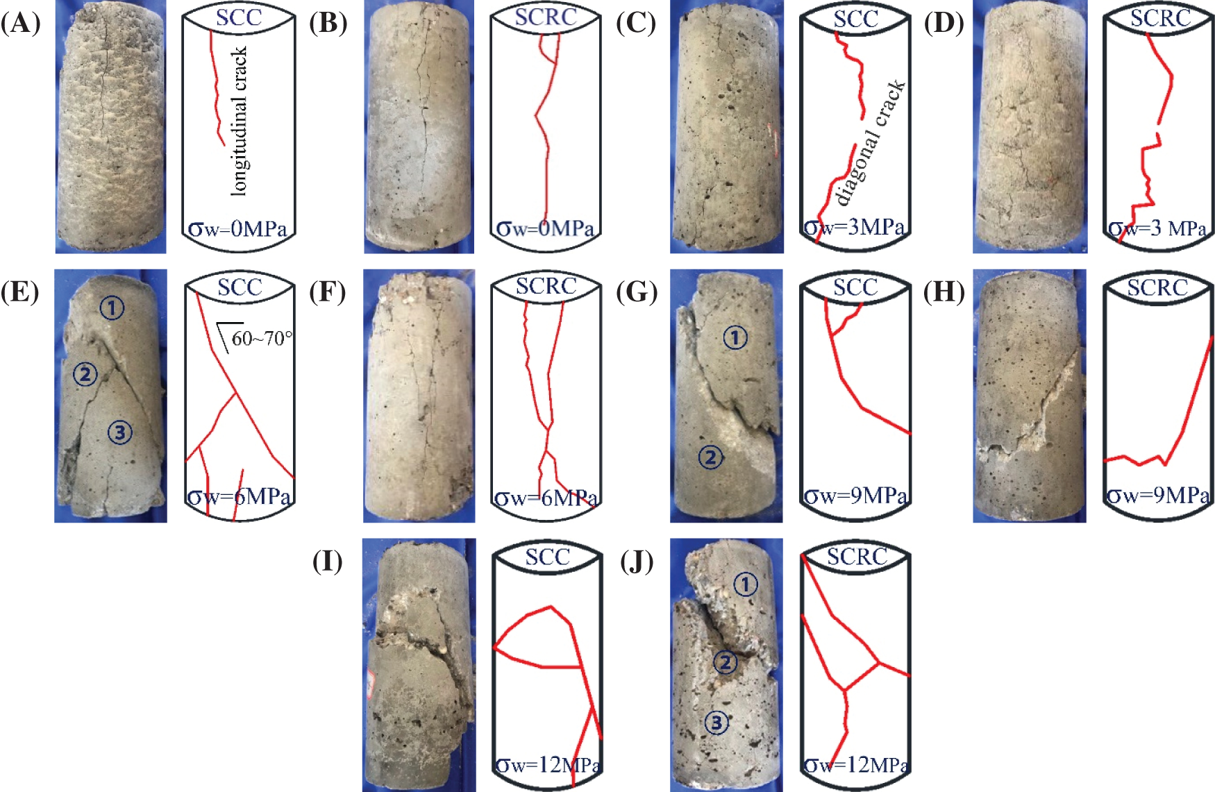
Figure 6: The failure modes of specimens. (A, C, E, G, I) SCC. (B, D, F, H, J) SCRC
3.3 Stress-Strain Curves of Triaxial Compression
The compressive stress-strain (σ-ε) curves are the key to determine the mechanical behavior of the specimens, as shown in Fig. 7. The stress-strain curves of SCRC experienced a similar trend to those of SCC in the elastic rising phase and plastic rising phase, and the plastic rising phase started roughly at 0.7–0.8 times the peak stress. However, SCRC differed significantly from SCC in terms of the behavior of softening descent branch and the effect of the variables on the properties.
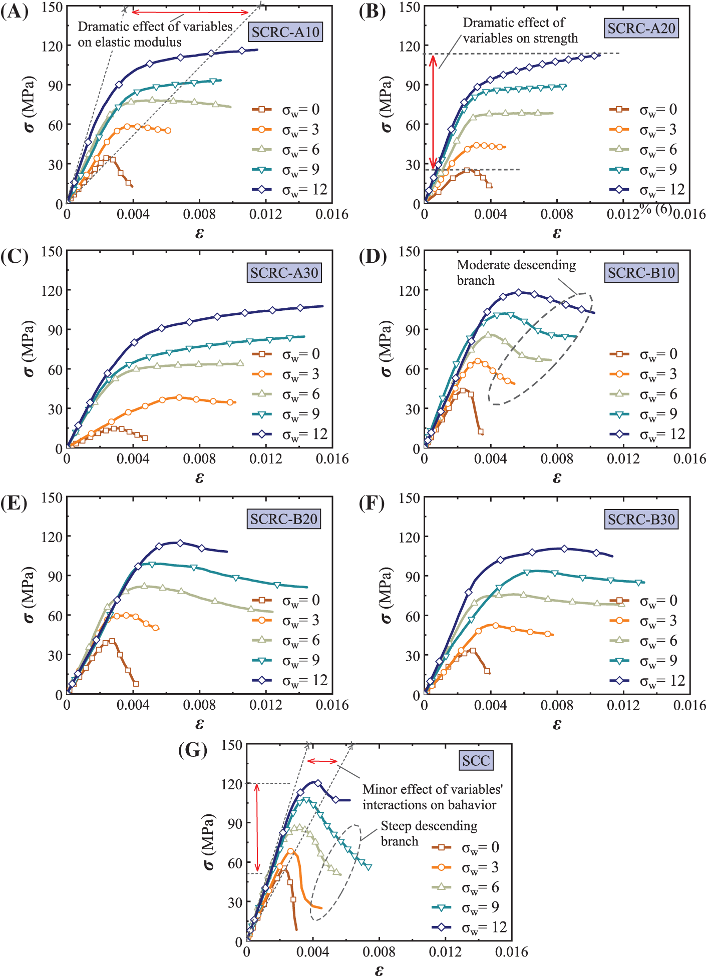
Figure 7: The stress-strain curves of specimens. (A~C) SCRC-A. (D~F) SCRC-B. (G) SCC
The results showed that the compressive behaviors, e.g., initial elastic modulus, peak stress, and peak strain, were improved significantly with the increase of the lateral confining stress, which limited the transverse deformation and crack expansion. In particular, the presence of rubber made the improvement of compression performance by lateral stress more significant, as will be analyzed in detail later. In addition, SCRC-A possessed a milder descent phase or even no descent phase compared to SCRC-B. The reason is that the rubber aggregates act like discontinuous energy-consuming matrices during the loading process, while the number of rubber powder per unit volume of the specimen is more than that of the rubber particles. This leads to better energy dissipation ability of SCRC-A and retards its damage.
Fig. 8 shows the peak stress (σcc), and Figs. 8B and 8C are the corresponding strength loss ratio (γ) of SCRC to SCC based on Eq. (2).The effect of lateral stress on the peak stress is nearly linear, while the magnitude of the effect varies depending on the rubber types and content. It is clear that the strength loss ratio decreases with increasing lateral stress. For example, for SCRC-A and SCRC-B, the uniaxial strength loss ranged from 37%–73% and 20%–39%, respectively, while the triaxial strength loss at a lateral stress of 9 MPa ranged from 14%–22% and 5%–13%, respectively.

Figure 8: Effect of test variables on peak stress. (A) Peak stress of specimens. (B~C) Strength loss ratio between SCRC and SCC. (D) Normalized peak stress-lateral stress relation
where σcc,SCC and σcc,SCRC are the peak stress of SCC and SCRC, respectively.
An important conclusion that can be drawn is that the strength loss becomes more and more severe as the rubber content increases. The reason for this is the lower strength of rubber and the adhesion between rubber and cement paste [12] compared to other aggregates. Moreover, the presence of rubber increases the porosity and decreases the effective bearing surface, which can be seen in Fig. 5.
Another important conclusion is that rubber powder caused more severe strength loss than rubber particles at the same content. This is because the specific surface area (i.e., the ratio of area to volume) of rubber powder is larger compared with the rubber particles, and it has worse adhesion with the cement paste. In that case, the force transfer performance between the rubber powder and cement paste becomes weaker, and the rubber powder even shows overall peeling, which can be seen in Fig. 9. On the contrary, the bond between rubber particles and cement paste is better and the degree of synergy is higher, so the internal cracking is slight. In addition, the increase in the content of rubber powder leads to an increased probability of its uneven distribution in the concrete, which likewise aggravates the strength loss.
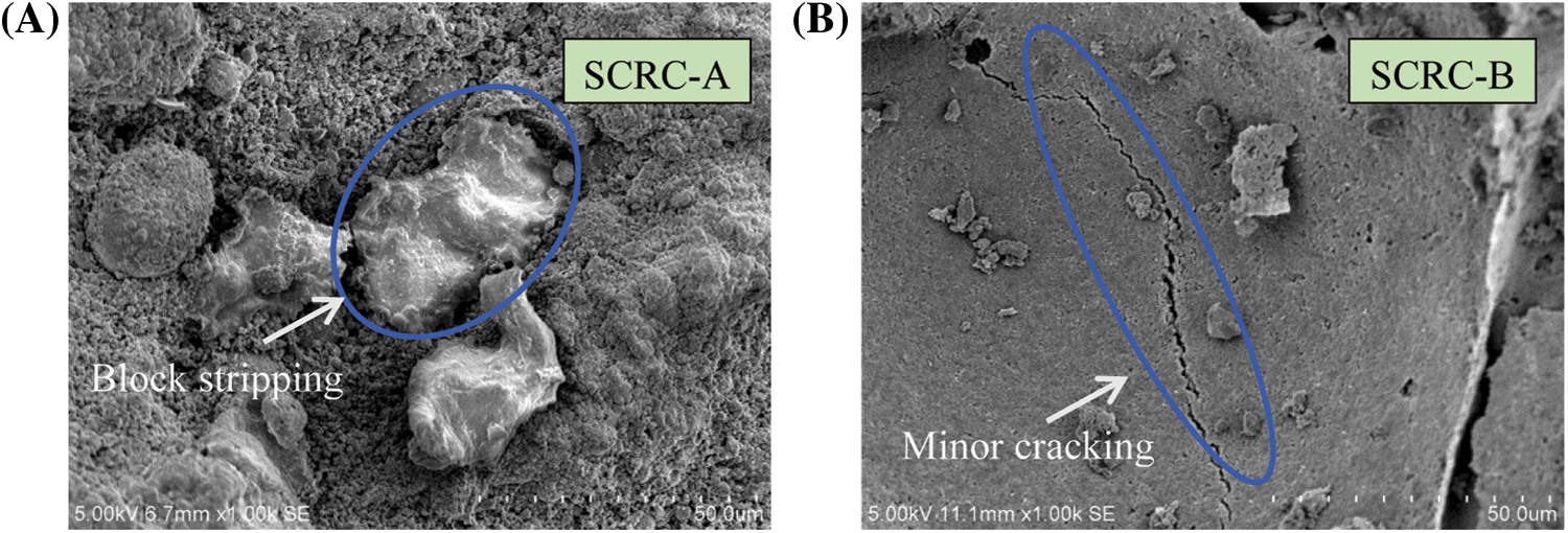
Figure 9: SEM images of SCRC after testing
A further novel finding is that at a lateral stress of 12 MPa, the strength losses were 3%, 7%, 11% for SCRC-A and 2%, 5%, 8% for SCRC-B when the rubber content was 10%, 20%, 30%, respectively. Therefore, a practical suggestion is given that the replacement rate limits for rubber powder and rubber particles can be taken as 20% and 30%, respectively, only when the lateral stress reaches 12 MPa.
Given the trend line of the relationship between peak stress and lateral stress, a linear equation was fitted using Origin software, following the least square method, as shown in Fig. 8D, where f0 is the peak stress in the unconstrained case. The fitting effect was judged according to R2, and the closer its value was to 1, the better the prediction effect of the equation. By comparing the slopes of the equations, it was found that the effect of lateral stress on the compressive strength was more significant in SCRC compared to SCC, with the greatest enhancement in SCRC-A.
Fig. 10 shows the effect of variables on peak strain (εcc), where the enhancement ratio (η) of SCRC to SCC is based on the Eq. (3). Consistent with the findings in the literature [26], both lateral stress and rubber aggregates improved the peak strain of SCRC, with the latter having a more significant effect. The reason for this is that rubber has a lower modulus of elasticity and produces better deformation properties relative to natural sand. Moreover, due to the larger contact area between the rubber powder and cement paste, the peak strain of the SCRC-A was larger than that of the SCRC-B at the same content. In terms of the degree of peak strain improvement, SCRC-A and SCRC-B even reached 3.1 and 1.0, respectively.
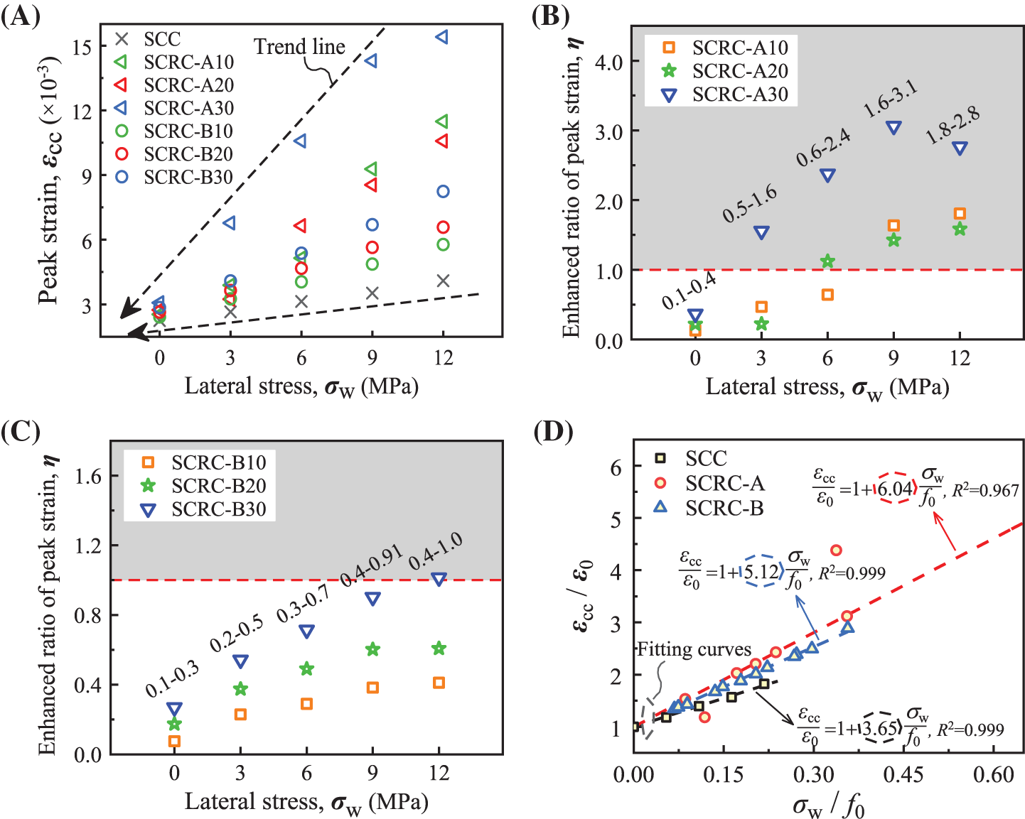
Figure 10: Effect of test variables on peak strain. (A) Peak strain of specimens. (B~C) Enhancement ratio of peak strain between SCRC and SCC. (D) Normalized peak strain-lateral stress relation
Consistent with the method in Fig. 8D, the linear prediction equations for the relationship between the peak strain and lateral stress were shown in Fig. 10D, where ε0 is the peak strain in the unconstrained case. Comparing the slopes of the equations, it was again found that the lateral constraint stress enhanced the peak strain for SCRC-A more than SCC and SCRC-B, implying a better deformability.
where εcc,SCC and εcc,SCRC are the peak strain of SCC and SCRC, respectively.
Toughness reflects the ability of a material to absorb energy and plastically deform without fracturing. According to the method proposed in the research [7], as shown in Fig. 11A, the toughness index (TI) can be expressed as an area ratio as per Eq. (4), and the calculated results are plotted in Fig. 11B.
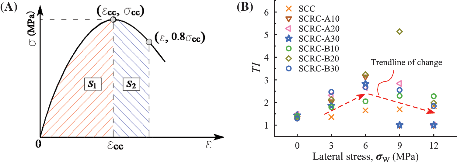
Figure 11: Toughness index. (A) Calculating principle. (B) Calculated results
where S1 and S2 are the areas of the red and blue regions under the stress-strain curves, respectively.
The results showed that the toughness of SCRC was generally better than that of SCC, which was attributed to the enhancement effect of the rubber on the post-peak deformation capacity. The rubber type had little effect on the toughness, while the presence of lateral stress made the toughness advantage of SCRC over SCC more prominent and most pronounced at a lateral stress of 6 MPa. Therefore, as a recommendation, triaxial compressive SCRC with a lateral stress of 6 MPa can be used preferentially to improve the energy absorption capacity of the structure.
The failure and strength of materials under multiaxial stresses is a common concern in engineering science. As one of the classical strength theories, Mohr-Coulomb failure theory is often used to describe the response of brittle materials or materials with much higher compressive strength than tensile strength under combined shear and normal stresses. Mohr-Coulomb failure theory states that a material will fail when the shear stress in the oblique section exceeds the shear strength. Considering that SCRC exhibited oblique shear damage under triaxial stresses, and that the presence of rubber severely weakened the cohesion between aggregates, the Mohr-Coulomb theory was chosen as the failure criterion for SCRC.
According to the Mohr-Coulomb theory, strength failure envelopes were made for a series of Mohr circles, as shown in Fig. 12. In agreement with the study [27], the damage shear stress (τ) and normal stress (σ) showed a significant nonlinear relationship, as shown in Eq. (5). Then the control parameters therein were obtained by Origin software based on the least square method, as shown in Table 4. At 30% rubber powder content, the cohesion decreases significantly, which is critical for shear strength, thus again validating the reasonableness of the content recommendation in Section 3.4.
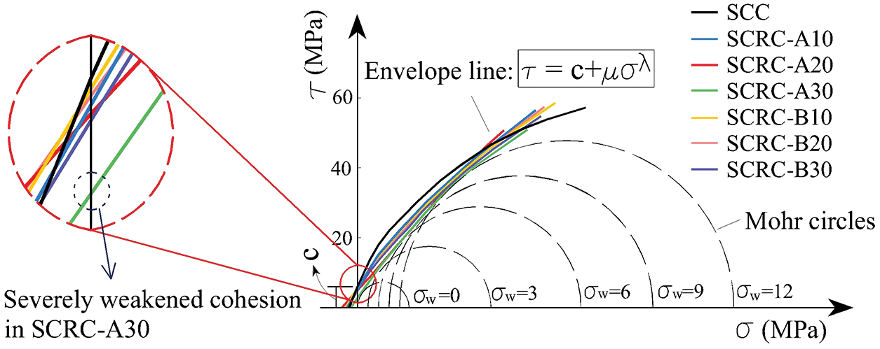
Figure 12: Mohr-Coulomb stress circular clusters and its failure envelope of specimens
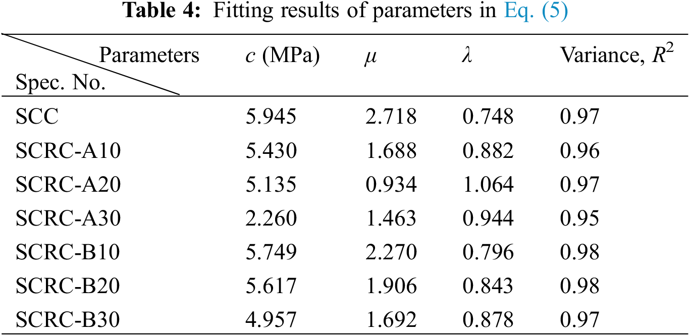
where c is the cohesion, μ and λ are control parameters.
To facilitate engineering applications, Eq. (5) is converted into Eq. (6) using uniaxial compressive strength (f0) for normalization, and the corresponding prediction results are shown in Fig. 13.

Figure 13: Relationship between normalized τ/ f0 and σ/ f0. (A) SCRC-A. (B) SCRC-B
where
5 Stress-Strain Constitutive Model
The stress-strain relationship is a macroscopic reflection of the mechanical behavior, and many scholars have proposed different constitutive models for concrete theoretically and experimentally. Hognestad et al. [34–36] used quadratic parabola to describe the rising portion of the compressive behavior, while linear equation, constant and linear bifurcation were used to describe the descending portion, respectively. However, this cannot take into account the effects caused by changes in the type of aggregates and restraint conditions and is therefore difficult to apply to different types of concrete. On this basis, although Sheikh et al. [37] introduced post-peak characteristic points to determine the behavior of the descending portion for hoop-constrained concrete, it still failed to address the limitations of the above constitutive models. To this end, based on extensive studies of stress-strain behavior and the influence of variables, e.g., raw materials, water-cement ratio, strength and stress state, on the shape of the stress-strain curve, Guo et al. [38] proposed a constitutive models containing shape control parameters, i.e., “a” and “b”, to predict the stress-strain relationship, as shown in Eq. (7). The formula has wide applicability and has been included in the prediction method of concrete mechanical behavior in the Chinese code (GB 50010-2010) [39]. Therefore, Guo model was adopted in this paper to verify stress-strain mechanical behavior of SCRC.
where y = σ/f0, x = ε/ε0. The “a” and “b” are the control parameters of the ascending and descending portions of the curve, respectively.
5.1 The Case of Uniaxial Compression
Fig. 14 shows the predicted curves, and the corresponding fitting values of “a” and “b” determined by least square method are listed in Table 5. The Guo model can well describe the uniaxial test curve of this paper, and the parameter a show an increasing trend with an increase in rubber content. It can be noted that the influence of rubber types on the parameter “a” is imperceptible and therefore not considered. Based on the trend of the relationship between the parameter “a” and rubber content, a second-order parabola was used to make predictions, as shown in Fig. 15A. As for the post-peak region, the influence of rubber types on parameter “b” was apparent and should be discussed. With the increase of rubber content, the parameter “b” of both rubber type specimens shows an obvious decreasing trend, but the trend lines are different. That is, the parameter “b” of rubber particles specimens decreases linearly with increasing rubber content, while that of rubber powder specimens shows a second-order parabolic relationship with rubber content. The predicted results are shown in Fig. 15B.
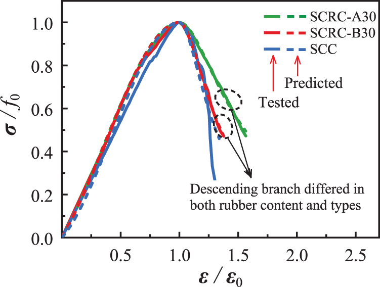
Figure 14: Partial comparison between experimental and predicted stress-strain curves for the uniaxial compression case
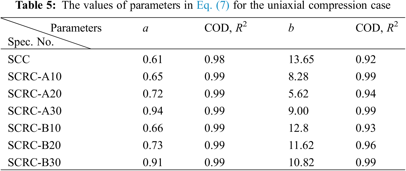
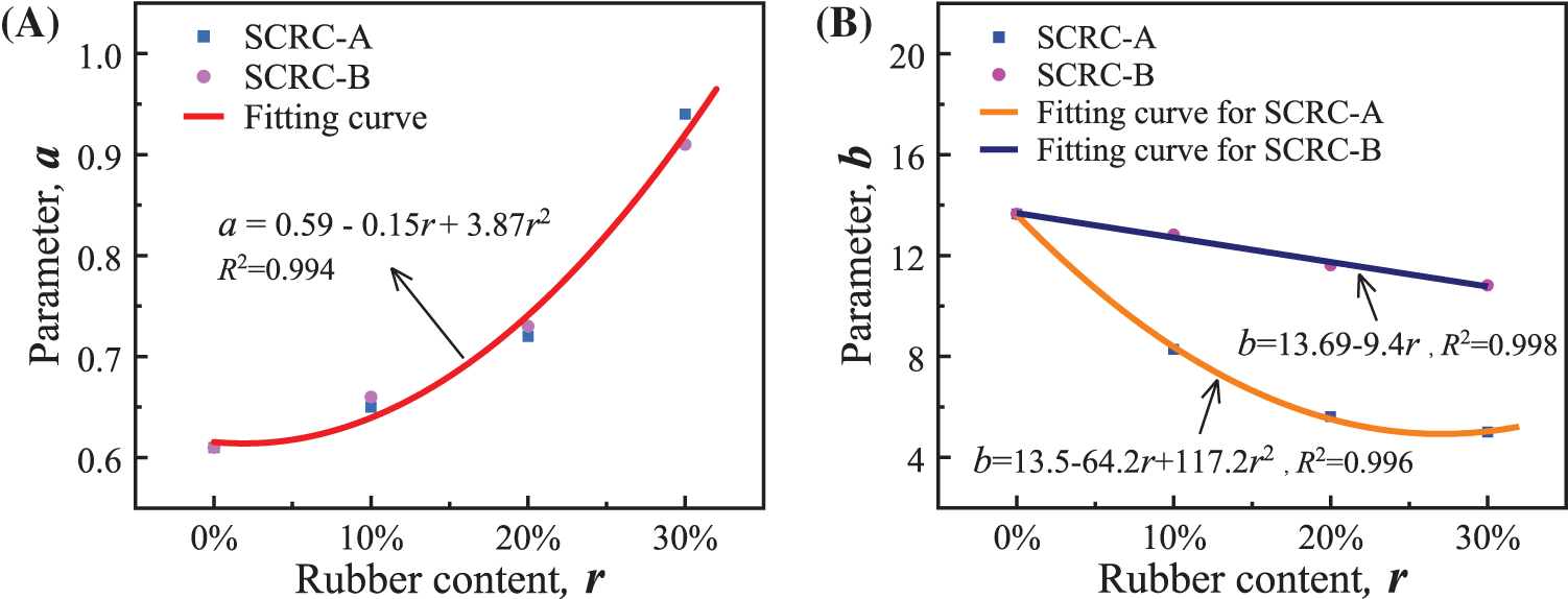
Figure 15: The relationship of rubber content and model parameters. (A) a-r. (B) b-r
5.2 The Case of Triaxial Compression
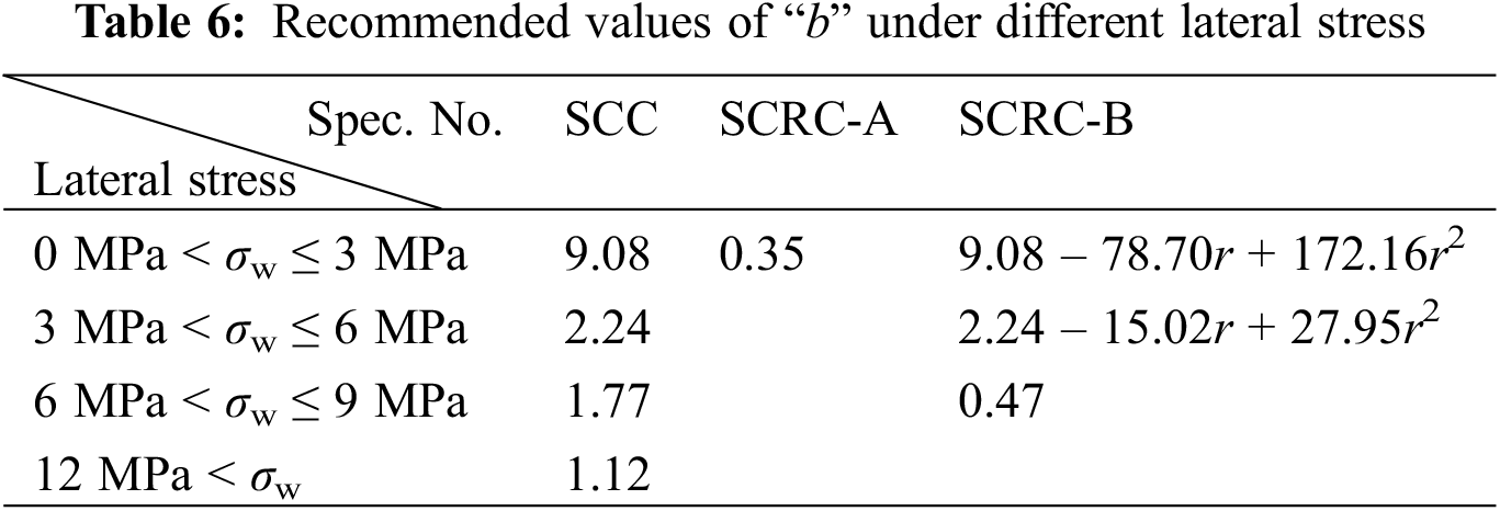
Fig. 16 shows the partial comparison between the experimental stress-strain curves and predicted curves calculated by Eq. (7) for the triaxial compression case at the lateral stress of 3 MPa, and the results of parameters are listed in Fig. 17. It can be found that when the rubber content was 10%, parameter “a” increased with the increase of lateral stress. However, when rubber content exceeded 20%, the variation of parameter “a” with lateral stress was not significant. For SCRC-A, rubber content and lateral stress had little effect on parameter “b”, because there was almost no descending stage for this kind of concrete. For SCRC-B, when the lateral stress exceeded 6 MPa, the influence of rubber content on parameter “b” was weak. Therefore, the values of “b” for rubberized concrete at lateral stresses were recommended, as shown in Table 6.
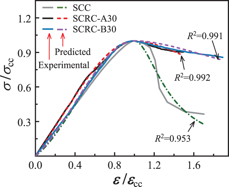
Figure 16: Partial comparison between predicted and experimental stress-strain curves for the triaxial compression case

Figure 17: Fitting results of parameters in Eq. (7) for the triaxial compression case. (A) The values of “a”. (B) The values of “b”
The conventional triaxial compression tests, together with fluidity test and microstructural observations, revealed the effect of rubber type and rubber content on the triaxial compression performance of SCRC. The following conclusions can be drawn:
1. The rubber aggregates increased air voids and micro-cracks in the concrete mixture. The flowability of SCRC decreased with increasing rubber content but was little affected by the rubber type.
2. Under uniaxial compression, the specimens SCRC exhibited longitudinal splitting failure. Under triaxial compression, the specimens SCRC showed oblique shear failure.
3. Compared to ordinary SCC, SCRC had a more moderate descending branch and superior deformation capacity. The presence of lateral stress significantly improved the compressive properties of SCRC, e.g., initial elastic modulus, peak strength and peak strain, with an enhancement range of 3%–73% for peak stress.
4. Although the addition of rubber reduced the compressive strength of SCRC to some extent, it can substantially improve the deformation capacity and toughness, and made the lateral stress more effective in improving the compressive performance, with the improvement range of 0.1–3.1 times for peak strain. The effect of rubber powder was more significant than that of rubber particles.
5. Considering the compressive performance and deformation capacity, it was recommended that when SCRC is applied to the design of structures with lateral stress not less than 12 MPa, the content limits of rubber powder and rubber particles are 20% and 30%, respectively, with the latter being the preferred option.
6. Mohr-coulomb theory was used as the failure criterion of SCRC with different rubber types.
7. Guo model, which considered the effects of variables, can reveal the triaxial stress-strain behavior of SCRC well.
The results obtained in this study can provide a valuable reference for the design and application of SCRC in practical projects, especially those involving three-way compression states and requiring high-quality deformation and energy dissipation. In view of the preliminary investigation of the triaxial performance of SCRC and the variation pattern of triaxial constitutive model parameters with variables, the sample size will be expanded later to further investigate the dual effects of lateral stress and rubber content on the constitutive model, especially for SCRC containing rubber powder.
Funding Statement: This work is supported by National Natural Science Foundation of China (Project No. 51468003) and Natural Science Foundation of Guangxi Province (Project No. 2018GXNSFAA050007). The financial support is gratefully acknowledged.
Conflicts of Interest: The authors declare that they have no conflicts of interest to report regarding the present study.
References
1. Apergis, N., Gozgor, G., Lau, C. K. (2021). Globalization and environmental problems in developing countries. Environmental Science and Pollution Research, 28(26), 33719–33721. DOI 10.1007/s11356-021-14105-z. [Google Scholar] [CrossRef]
2. Shi, J., Liu, Y., Xu, H., Peng, Y., Yuan, Q. et al. (2022). The roles of cenosphere in ultra-lightweight foamed geopolymer concrete (UFGC). Ceramics International, 48(9), 12884–12896. DOI 10.1016/j.ceramint.2022.01.161. [Google Scholar] [CrossRef]
3. Wang, L., Wang, J., Wang, H., Fang, Y., Shen, W. et al. (2022). Eco-friendly treatment of recycled concrete fines as supplementary cementitious materials. Construction and Building Materials, 322(5), 126491. DOI 10.1016/j.conbuildmat.2022.126491. [Google Scholar] [CrossRef]
4. Shi, J., Liu, B., He, Z., Liu, Y., Jiang, J. et al. (2021). A green ultra-lightweight chemically foamed concrete for building exterior: A feasibility study. Journal of Cleaner Production, 288(1), 125085. DOI 10.1016/j.jclepro.2020.125085. [Google Scholar] [CrossRef]
5. Shi, J., Tan, J., Liu, B., Chen, J., Dai, J. et al. (2021). Experimental study on full-volume slag alkali-activated mortars: Air-cooled blast furnace slag versus machine-made sand as fine aggregates. Journal of Hazardous Materials, 403(21), 123983. DOI 10.1016/j.jhazmat.2020.123983. [Google Scholar] [CrossRef]
6. Thomas, B. S., Gupta, R. C. (2016). A comprehensive review on the applications of waste tire rubber in cement concrete. Renewable and Sustainable Energy Reviews, 54(6), 1323–1333. DOI 10.1016/j.rser.2015.10.092. [Google Scholar] [CrossRef]
7. Khaloo, A. R., Dehestani, M., Rahmatabadi, P. (2008). Mechanical properties of concrete containing a high volume of tire-rubber particles. Waste Management, 28(12), 2472–2482. DOI 10.1016/j.wasman.2008.01.015. [Google Scholar] [CrossRef]
8. Zheng, L., Huo, X. S., Yuan, Y. (2008). Strength, modulus of elasticity, and brittleness index of rubberized concrete. Journal of Materials in Civil Engineering, 20(11), 692–699. DOI 10.1061/(ASCE)0899-1561(2008)20:11(692). [Google Scholar] [CrossRef]
9. Thomas, B. S., Kumar, S., Mehra, P., Gupta, R. C., Joseph, M. et al. (2016). Abrasion resistance of sustainable green concrete containing waste tire rubber particles. Construction and Building Materials, 124(2), 906–909. DOI 10.1016/j.conbuildmat.2016.07.110. [Google Scholar] [CrossRef]
10. Xue, J., Shinozuka, M. (2013). Rubberized concrete: A green structural material with enhanced energy-dissipation capability. Construction and Building Materials, 42(4), 196–204. DOI 10.1016/j.conbuildmat.2013.01.005. [Google Scholar] [CrossRef]
11. Zheng, L., Huo, X. S., Yuan, Y. (2008). Experimental investigation on dynamic properties of rubberized concrete. Construction and Building Materials, 22(5), 939–947. DOI 10.1016/j.conbuildmat.2007.03.005. [Google Scholar] [CrossRef]
12. Turatsinze, A., Bonnet, S., Granju, J. L. (2004). Mechanical characterisation of cement-based mortar incorporating rubber aggregates from recycled worn tyres. Building and Environment, 40(2), 221–226. DOI 10.1016/j.buildenv.2004.05.012. [Google Scholar] [CrossRef]
13. Thomas, B. S., Gupta, R. C. (2016). Properties of high strength concrete containing scrap tire rubber. Journal of Cleaner Production, 113(12), 86–92. DOI 10.1016/j.jclepro.2015.11.019. [Google Scholar] [CrossRef]
14. Thomas, B. S., Gupta, R. C., Panicker, V. J. (2016). Recycling of waste tire rubber as aggregate in concrete: Durability-related performance. Journal of Cleaner Production, 112(7), 504–513. DOI 10.1016/j.jclepro.2015.08.046. [Google Scholar] [CrossRef]
15. Thomas, B. S., Gupta, R. C., Panicker, V. J. (2015). Experimental and modelling studies on high strength concrete containing waste tire rubber. Sustainable Cities and Society, 19(1), 68–73. DOI 10.1016/j.scs.2015.07.013. [Google Scholar] [CrossRef]
16. Thomas, B. S., Gupta, R. C. (2015). Long term behaviour of cement concrete containing discarded tire rubber. Journal of Cleaner Production, 102(1), 78–87. DOI 10.1016/j.jclepro.2015.04.072. [Google Scholar] [CrossRef]
17. Thomas, B. S., Gupta, R. C., Kalla, P., Cseteneyi, L. (2014). Strength, abrasion and permeation characteristics of cement concrete containing discarded rubber fine aggregates. Construction and Building Materials, 59(1), 204–212. DOI 10.1016/j.conbuildmat.2014.01.074. [Google Scholar] [CrossRef]
18. Aslani, F., Ma, G., Yim, W., Dominic, L., Tran, L. et al. (2018). Experimental investigation into rubber granules and their effects on the fresh and hardened properties of self-compacting concrete. Journal of Cleaner Production, 172(7), 1835–1847. DOI 10.1016/j.jclepro.2017.12.003. [Google Scholar] [CrossRef]
19. Najim, K. B., Hall, M. R. (2010). A review of the fresh/hardened properties and applications for plain- (PRC) and self-compacting rubberised concrete (SCRC). Construction and Building Materials, 24(11), 2043–2051. DOI 10.1016/j.conbuildmat.2010.04.056. [Google Scholar] [CrossRef]
20. Topçu, İ. B., Bilir, T. (2009). Experimental investigation of some fresh and hardened properties of rubberized self-compacting concrete. Materials and Design, 30(8), 3056–3065. DOI 10.1016/j.matdes.2008.12.011. [Google Scholar] [CrossRef]
21. Aslani, F. (2015). Mechanical properties of waste tire rubber concrete. Journal of Materials in Civil Engineering, 28(3), 4015152. DOI 10.1061/(ASCE)MT.1943-5533.0001429. [Google Scholar] [CrossRef]
22. Si, R., Guo, S., Dai, Q. (2017). Durability performance of rubberized mortar and concrete with NaOH-Solution treated rubber particles. Construction and Building Materials, 153(10), 496–505. DOI 10.1016/j.conbuildmat.2017.07.085. [Google Scholar] [CrossRef]
23. Rivas-Vázquez, L. P., Suárez-Orduña, R., Hernández-Torres, J., Aquino-Bolaños, E. (2015). Effect of the surface treatment of recycled rubber on the mechanical strength of composite concrete/rubber. Materials and Structures, 48(9), 2809–2814. DOI 10.1617/s11527-014-0355-y. [Google Scholar] [CrossRef]
24. Li, G., Pang, S. S., Ibekwe, S. I. (2011). FRP tube encased rubberized concrete cylinders. Materials and Structures, 44(1), 233–243. DOI 10.1617/s11527-010-9622-8. [Google Scholar] [CrossRef]
25. Duarte, A. P. C., Silva, B. A., Silvestre, N., de Brito, J., Júlio, E. et al. (2016). Tests and design of short steel tubes filled with rubberised concrete. Engineering Structures, 112(7), 274–286. DOI 10.1016/j.engstruct.2016.01.018. [Google Scholar] [CrossRef]
26. Gholampour, A., Ozbakkaloglu, T., Hassanli, R. (2017). Behavior of rubberized concrete under active confinement. Construction and Building Materials, 138(6), 372–382. DOI 10.1016/j.conbuildmat.2017.01.105. [Google Scholar] [CrossRef]
27. Chen, Y., Chen, Z., Xu, J., Liu, E. M., Wu, B. (2019). Performance evaluation of recycled aggregate concrete under multiaxial compression. Construction and Building Materials, 229(10), 116935. DOI 10.1016/j.conbuildmat.2019.116935. [Google Scholar] [CrossRef]
28. Meng, E., Yu, Y., Yuan, J., Qiao, K., Su, Y. (2017). Triaxial compressive strength experiment study of recycled aggregate concrete after high temperatures. Construction and Building Materials, 155(5), 542–549. DOI 10.1016/j.conbuildmat.2017.08.101. [Google Scholar] [CrossRef]
29. The National Standards Compilation Group of the People’s Republic of China (2007). GB 175-2007 Common Portland Cement. China: China Standards Press (in Chinese). http://www.jianbiaoku.com/webarbs/book/83154/2286052.shtml. [Google Scholar]
30. The National Standards Compilation Group of the People’s Republic of China (2011). GB/T 14685-2011 Pebble and Crushed Stone for Construction. China: China Standards Press (in Chinese). http://www.jianbiaoku.com/webarbs/book/12073/371021.shtml. [Google Scholar]
31. Ministry of Housing and Urban-Rural Development of the People’s Republic of China (2012). JGJ/T 283-2012 Technical Specification for Application of Self-Compacting Concrete. China: China Building Industry Press (in Chinese). http://www.jianbiaoku.com/webarbs/book/10888/303760.shtml. [Google Scholar]
32. Ministry of Housing and Urban-Rural Development of the People’s Republic of China (2011). JGJ 55-2011 Specification for Mix Proportion Design of Ordinary Concrete. China: China Building Industry Press (in Chinese). http://www.jianbiaoku.com/webarbs/book/10342/690979.shtml. [Google Scholar]
33. The National Standards Compilation Group of the People’s Republic of China (2013). GB/T 50266-2013 Standard for Test Methods of Engineering Rock Mass. China: China Standards Press (in Chinese). http://www.jianbiaoku.com/webarbs/book/261/891298.shtml. [Google Scholar]
34. Hognestad, E., Hanson, N. W. (1955). Concrete stress distribution in ultimate strength design. Journal of the American Concrete Institute, 52(12), 455–480. [Google Scholar]
35. Rüsch, H. (1960). Research toward a general flexural theory for structural concrete. Journal of the American Concrete Institute, 57(7), 1–28. [Google Scholar]
36. Kent, D. C., Park, R. (1971). Flexural members with confined concrete. Journal of the Structural Division, 97(7), 1969–1990. DOI 10.1061/JSDEAG.0002957. [Google Scholar] [CrossRef]
37. Sheikh, S. A., Uzumeri, S. M. (1982). Analytical model for concrete confinement in tied columns. Journal of the Structural Division, 108(12), 2703–2722. DOI 10.1061/JSDEAG.0006100. [Google Scholar] [CrossRef]
38. Guo, Z. H., Shi, X. D. (2003). Reinforced concrete theory and analyse. Compressive Stress-Strain Complete Curve, pp. 20–25 (in Chinese). China: Tsinghua University Press. [Google Scholar]
39. The National Standards Compilation Group of the People’s Republic of China (2010). GB/T 50010-2010 Code for the Design of Reinforced Concrete Structures. China: China Standards Press (in Chinese). http://www.jianbiaoku.com/webarbs/book/209/2438396.shtml. [Google Scholar]
Cite This Article
 Copyright © 2023 The Author(s). Published by Tech Science Press.
This work is licensed under a Creative Commons Attribution 4.0 International License , which permits unrestricted use, distribution, and reproduction in any medium, provided the original work is properly cited.
 Downloads
 Citation Tools