
 Submit a Paper
 Propose a Special lssue
 Open Access
ARTICLE

Displacement Field Variable Modeling Method for Heterogeneous Materials in Wind Power Blade Core Plates
School of Mechanical Engineering, Shandong University of Technology, Zibo, 255049, China
* Corresponding Author: Yongshuang Wen. Email:
Energy Engineering 2023, 120(2), 445-459. https://doi.org/10.32604/ee.2022.022223
Received 28 February 2022; Accepted 16 May 2022; Issue published 28 November 2022
 View Full Text
 Download PDF
Abstract
In order to study the mechanical properties of the heterogeneous core plate of the wind turbine blade, a modeling method of the core plate based on displacement field variables is proposed. Firstly, the wind turbine blade core plate was modeled according to the theory of modeling heterogeneous material characteristics. Secondly, the three-point bending finite element model of the wind turbine blade core plate was solved by the display dynamic equation to obtain the deformation pattern and force-deformation relationship of the core plate. Finally, the three-point bending static test was conducted to compare with the finite element analysis. The test results show that: the damage form of the wind turbine blade core plate includes elasticity, yield, and failure stages. The main failure modes are plastic deformation, core material collapse, and panel-core delamination. The failure load measured by the test is 1.59 kN, which is basically consistent with the load-displacement result obtained by the simulation, with a difference of only 1.9%, which verifies the validity and reliability of the model. It provides data references for wind turbine blade structure design.Keywords
According to the outline of the 14th Five-Year Plan and the proposal for 2035, China will be vigorously developing renewable energy and environmental protection industries accordingly. Wind power plays an important part of renewable energy’s irreplaceable role in modern society [1–4]. The core plate of a wind turbine has many applications in the whole blade and accounts for a relatively high cost in the whole wind turbine [5]. The blade core plate adopts a sandwich structure, the substrate is glass fiber laminate, and the core material is generally selected lightweight, high strength polyvinyl chloride foam. The adhesive combine substrate and material Affected by the on-site manufacturing process of PVC foam, the density of the produced PVC foam is inconsistent, resulting in a heterogeneous entity in the core plate of the processed wind turbine blades [6–8]. Therefore, there is an urgent need for better mechanical modeling of the blade core plate to study better the mechanical properties of the blade core plate, which can then provide a theoretical guarantee to improve the service life and safe operation of wind turbine blades.
At present, scholars at home and abroad have done a great deal of research on heterogeneous solid modeling methods. Kumar et al. [9] combined homogeneous units of structures and different material components into heterogeneous materials in the context of composite applications, but the model library needed to collect an even bigger amount of heterogeneous solid data and the workload was large. Qian et al. [10] proposed the S-set theory based on the R-set theory of solid modeling. Still, the model proposed according to its diffusion equation was difficult to represent the heterogeneous entities of biological materials. Gustafsson et al. [11] modeled the heterogeneous solids of the human femur based on the heterogeneous solid model of material feature representation. Yang et al. [12] reviewed the current status and development trends in the world of structural modeling techniques for heterogeneous composites. Although these research results have proved the effectiveness of the heterogeneous solid modeling method, the displacement field-based modeling method and its use in wind turbine blade testing have not been previously covered in any of the available work.
To solve the aforementioned problems, a heterogeneous solid model was established for the core material of wind turbine blades based on the displacement field theory. A three-point bending test was carried out on the wind power blade core plate sample to observe the distribution of strength, stress, and deformation. By comparing the load-displacement curve and deformation shape obtained from the experiment, the reliability of the modeling method for the displacement field of the heterogeneous material of wind turbine blade core plate the core can then be verified; it provides a theoretical data reference for the overall parameter performance of the wind turbine blade.
2.1 Core Plate Displacement Field Modeling
The blade core plate exists in the leading edge, trailing edge, and web, which has an irreplaceable role in increasing the strength of the structure, reducing the local instability, and improving the blade load resistance [13,14]. The problem of modeling the material properties of the blade core plate is a type of physical field modeling issue. Fig. 1 shows the comparison between heterogeneous material modeling and homogeneous material modeling. The suitable mathematical model is the fiber bundle model. This model can specify the display definition on the original geometry, constrain and control through differentiation and integration, and can maintain smoothness and analysis performance without discretizing and meshing the boundary and internal space of the entity, then express and calculate the core plate performance [15].
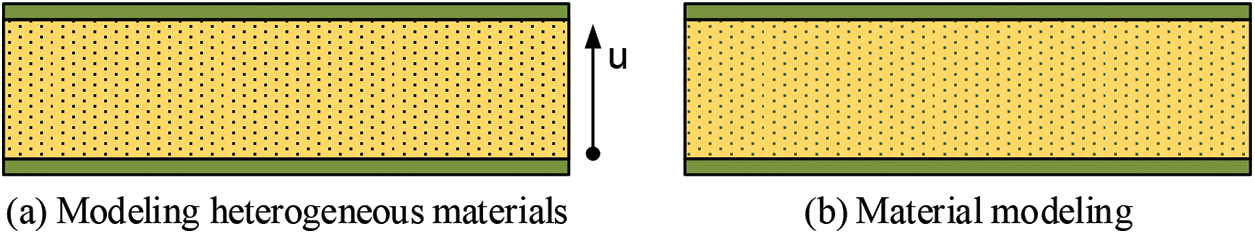
Figure 1: Comparison of homogeneous material modeling and heterogeneous material modeling
The core material property set are S and
where,
Concerning the material function of the distance, the material standard form is obtained by repeating the integral or differential transformation of L. The material function is known to be used to control the shear modulus,
Due to the uncertainty of environmental factors in the core plate field manufacturing, it is far from sufficient to explicitly define core plate’s material properties, and only represent the distance standard form locally. The original function can only be approximated by ignoring the remainder term. To reduce the error, define the unknown function
2.2 Fiberglass Panels Modeling
The upper and lower panels in the core plate are laminate structures composed of glass fibers, whose properties are mainly determined by the glass fiber monolayers’ mechanical properties, geometry, and boundary conditions [16,17]. It is known that the material elastic constants of each layer of glass fiber are (E1, E2, V12, G12), and the lay-up angle is
where,
The positive axis stiffness matrix Q can be derived from the single-layer glass fiber engineering elastic constants as follows:
Convert the main direction of the single-layer glass fiber composite material with the ply angle of 45° to the overall coordinate system XYZ, and obtain the coordinate conversion matrix of each layer:
Among them,
The stress correspondence for each glass fiber layer is:
Using the same method, the strain-stress relationship under coordinate transformation can be found as follows:
The in-plane stiffness coefficient of the upper and lower panels is calculated as:
where, the subscript s represents the sth layer; n means there are n layers in total.
where,
In-plane flexibility
The modulus of elasticity in the x-direction of the panels after regularization is:
where, h represents the thickness of the panel.
3 General Scheme and Finite Element Analysis
As shown in Fig. 2, the three-point bending static test of blade core plate consists of mechanical structure, hydraulic system, electrical control cabinet, and PC end. The mechanical network consists of a loading bracket, driveshaft, filament bar, and upper beam. The blade core plate is precisely placed on the fixture through the measuring device. The indenter is in contact with the core plate under the reaction of the lead screw for testing, and the other end of the indenter is connected to the upper beam through the force sensor. When working, the servo motor of the hydraulic system at the bottom of the mechanical structure drives the hydraulic pump to convert the mechanical energy into hydraulic energy, and the hydraulic oil enters the servo motor to work through the servo valve. At the same time, the force sensor converts the power into an electric signal through the transmitter and feeds it back to the upper computer.
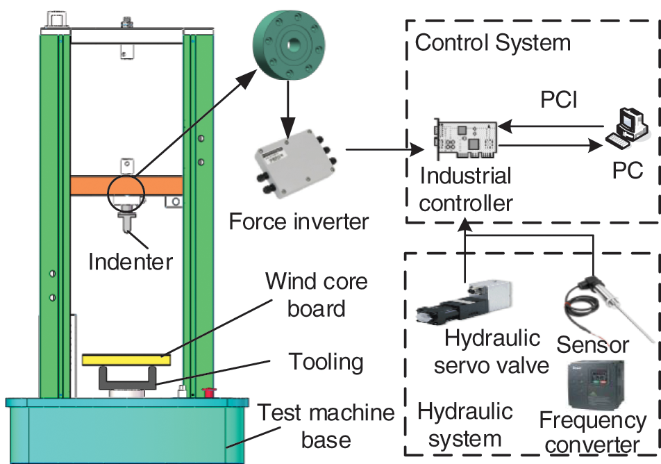
Figure 2: Design scheme drawing of three-point bending test machine for blade core plate
3.2 Lamination of Composite Materials
The blade core layup needs to add material properties, build a model, define the coordinate tool system, and define the direction selection set and layup parameters. It is set in the ACP-Pre module of the finite element analysis software Ansys workbench. Firstly, material properties were added. The orthotropic anisotropic glass fiber monomorphic strip material and heterogeneous solid material properties were added to the model. The material parameters are detailed in Table 1.
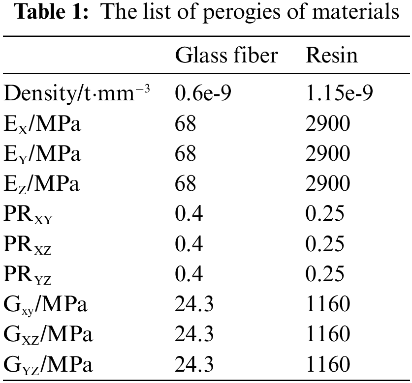
In Table 1: E is the modulus of elasticity; PR is Poisson’s ratio; G is shear modulus; X, Y, Z respectively represent the three directions of the material coordinate system.
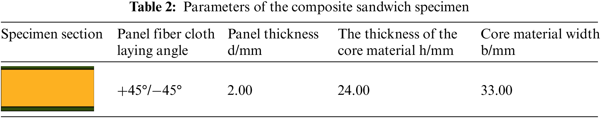
After the material properties were added, it created a cloth layer; and gave its glass fiber and core unit thickness. That thickness is thoroughly detailed in Table 2. The glass fiber units were layered to form a unit set; and were laminated according to the + 45°/−45 direction. Finally, the coordinate system was defined, and the zero direction of the ply was established; the bottom panel, the top panel, and the core material then was packed to be formed.
3.3 Numerical Simulation of Three-Point Bending Test
The explicit dynamic algorithm solved the finite element model of the three-point bending structure. The finite element model was pre-processed [18,19], including the elemental and material definition, mesh division, boundary condition definition and external load application. Linear condition constraints modeled homogeneous solids, and heterogeneous solids were modeled by laying up composite materials. The geometric dimensions in the finite element modeling were consistent with the experiments. The finite element model of the three-point bending structure is shown in Fig. 3.
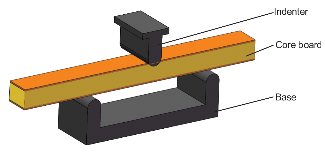
Figure 3: Three-point bending load-bearing solid model of glass fiber-polyvinyl chloride core plate
Numerical simulation of three-point bending structure was carried out after the composite material was laminated. The ACP preprocessing module and explicit dynamics were associated and shared in Ansys workbench to solve. For the analysis of three-point bending, referring to the work of Fries et al. [20,21], the Level set method global tracking algorithm was introduced. With this algorithm, the finite element model’s sensitivity to the mesh’s orientation was expected to be eliminated. For the pretreatment of the numerical simulation of the three-point bending structure, the material of the indenter and the support was first specified as high-strength alloy steel, namely 38CrMoAL.
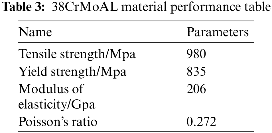
The material parameters are shown in Table 3. A custom material method was taken and input into the following engineering material database.
Secondly, set the contact relationship. The contact relationship between the indenter and the core plate was “surface-to-surface” friction contact, and the friction coefficient was 0.2. The contact relationship between the support and the core plate was frictionless contact. Since the fineness of meshing greatly influence the results of finite element analysis, high-quality mapped meshes were used for meshing. Its total number of nodes was 51813 and the total number of cells was 44905.
The finite element model obtained after meshing is shown in Fig. 4. Finally, added boundary conditions and applied external loads, where both the indenter and the support were set to rigid body.
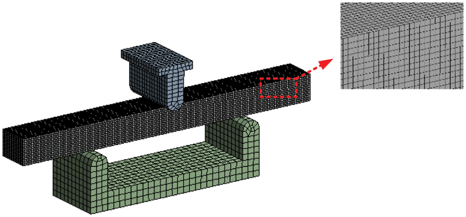
Figure 4: Three-point bending finite element model of glass fiber-polyvinyl chloride core material
By analyzing the working conditions involved, it became understood that the contact surface between the indenter and the blade core plate was the force-bearing surface. Finally, an external load was applied, a speed of 5 m/s was set, the direction was positioned to be straight down, and the end time was 0.04 s. There were only degrees of freedom to move in regarding of speed. In the analysis process, the rate of the indenter in the finite element analysis was much greater than the speed of the indenter movement in the experiment. The purpose was to eliminate the inertial force caused by the increase in speed. Perform dynamic solution after setting according to parameters.
After the finite element was pre-processed and solved, post-processing was then performed. The accuracy of the numerical simulation results was also verified according to the grid independence [22]. In Ansys workbench, the mesh-independent solution could be determined by setting the target value and having the software automatically perform multiple calculations. After each solution, the software automatically re-divided the mesh in the area that required further refinement, calculated the corresponding equivalent stress and compared it with the previous result. After completion, the computer solved again until the result difference met the set requirements. Therefore, the convergence was inserted in the result equivalent stress, setting a difference of 0%. After four calculations, the calculated failure load was 1.62 kN, which was only 0.08% different from the third calculation result, which met the calculation requirements. The obtained deformation shape is shown in Fig. 5.
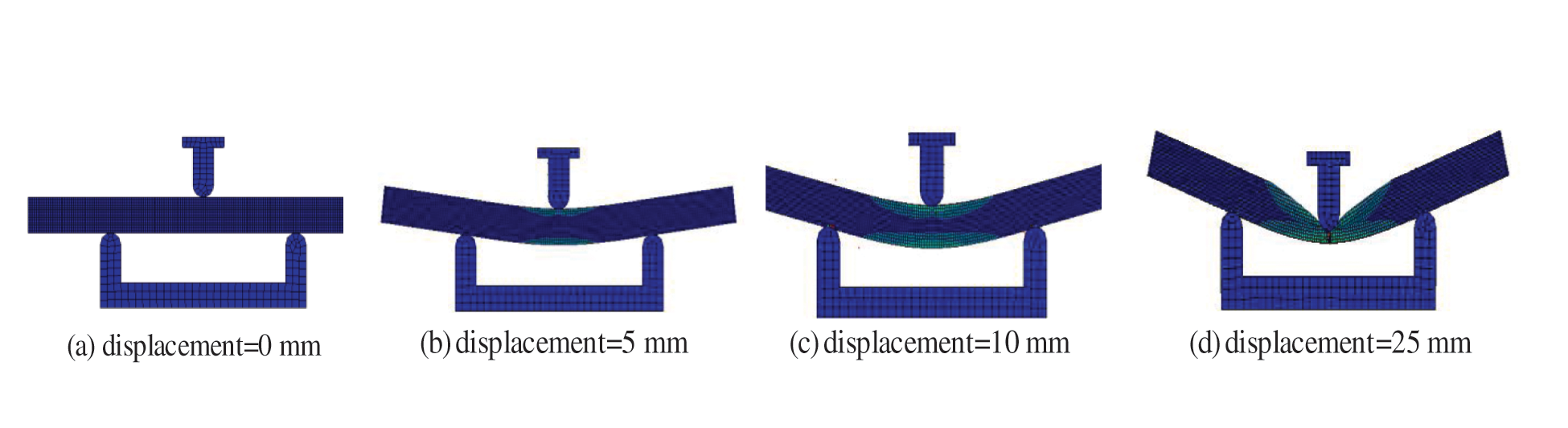
Figure 5: Three-point bending simulation deformation shape of glass fiber-polyvinyl chloride core plate
4 Test Platform Construction and Testing
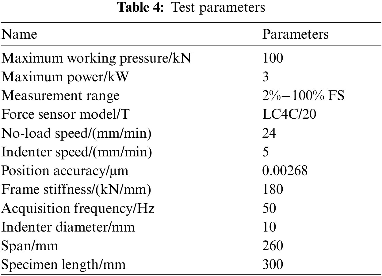
To study the bending mechanical properties of the wind turbine blade core plate, the relationship between the mid-span deflection of the blade core plate and the loading load was measured through a three-point bending test. The test consisted of an Instron5969 universal testing machine, a PC terminal, and an image acquisition system; those test parameters are shown in Table 4. During the test, the PC end controlled the indenter installed on the upper beam to contact the sample for the test. When a load was applied to the core plate in a three-point bending mode, the interface formed between the panel and its foam core material on the side close to the indenter mainly bore compressive stress. In contrast, the interface formed between the panel and its foam core material on the side far away from the indenter mainly bore tensile stress.
The PC terminal had the work of designing the control algorithm, collecting data, as well as storing and displaying the strain curve. The test site is shown in Fig. 6. The test took 5 test specimens for the test. The numbering rule was “the thickness of the upper panel-the thickness of the core board-the thickness of the lower panel-the repeatability test label”. For example in the test piece “2-30-2-A”, the repeatability number was A. The bending strength was calculated according to Eq. (14). The test referred to the standard GB/T 1456-2005 “Test Method for Flexural Performance of Sandwich Structures” [23]. In the test, the indenter adopted the control method of displacement loading and force unloading. The test object is shown in Fig. 7.
where,
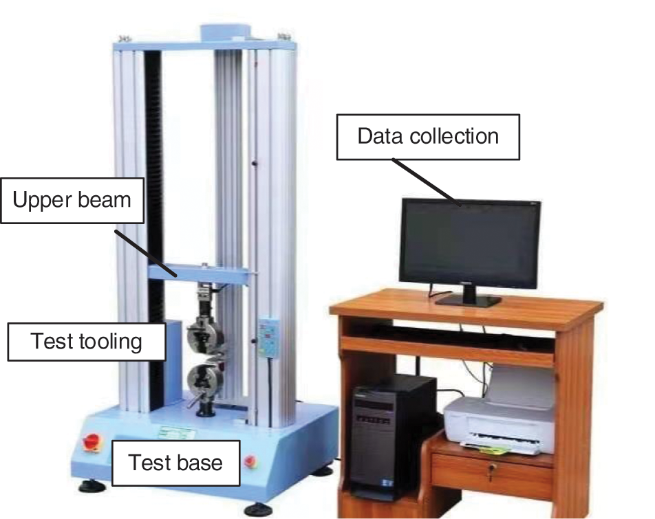
Figure 6: Three-point bending test of glass fiber-polyvinyl chloride core plate
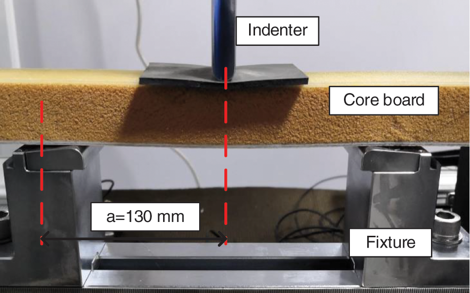
Figure 7: Schematic diagram of three-point bending experiment device
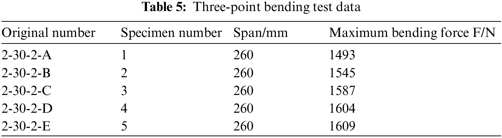
At the end of the test, the load-displacement curves fed back by the digital image system and the force sensor are shown in Fig. 8. The core plate could be divided from the curves into three stages in the whole bending deformation process: elasticity, yield, and failure [24–26]. The data of the three-point bending test are shown in Table 5.
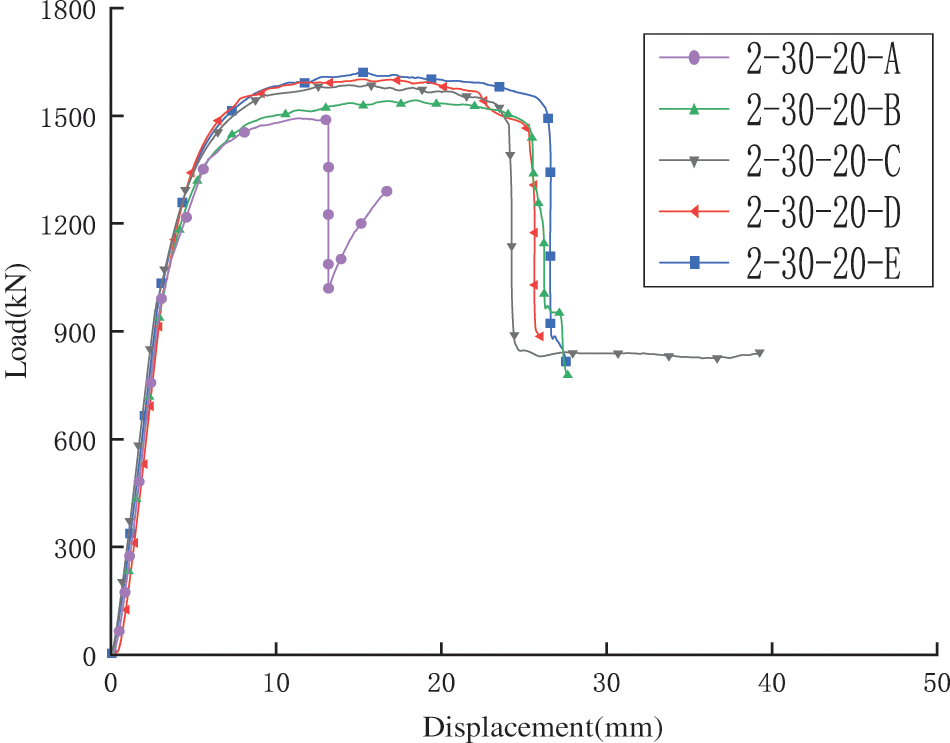
Figure 8: Load-displacement curves
The deformation of the core board is shown in Fig. 9.
(1) The first stage was the elastic stage. The load-displacement curve increased linearly and the core plate did have elastic deformation. The deformation of the core plate could restore to its original state after unloading.
(2) The second stage was the yield stage, in which the load remained stable and did not change obviously with the displacement increase. The upper ultimately plate completely failed and the core layer near the upper panel was gradually compacted.
(3) The third stage was the destruction stage, which showed that the upper panel had a sizealy local deformation, and the core material was compacted in the indenter area. The responses of each stage of the panel, core material, and the interface layer were not synchronized, and face-core delamination occurred.
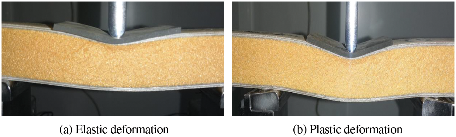
Figure 9: Physical image of core plate deformation
Fig. 10 reveals the internal failure mechanism of the blade core. After observation, it was found that the most likely failure modes of the core board were plastic deformation and core material collapse. At the same time, the face-core interface delamination occurred, and the delamination process extended from the indenter to both sides along the face-core interface.
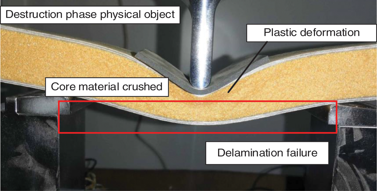
Figure 10: Core plate failure sample
By comparing the results of the finite element analysis of the core plate with the test results, the correctness of the simulation analysis method was verified from the core plate deformation form and load-displacement curve. From the deformation profile of the core plate shown in Fig. 11, it can be seen that the deformation shape obtained by the simulation is almost consistent with the test.
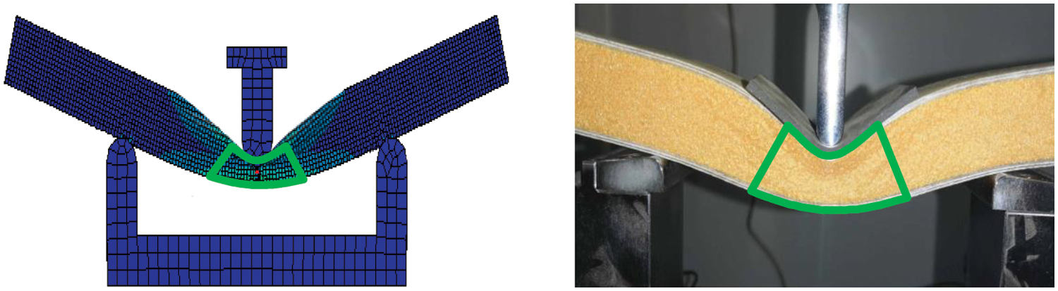
Figure 11: The simulation analysis and experimental comparison of three-point bending deformation of the core plate
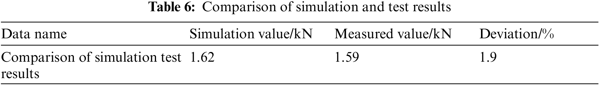
Fig. 12 demonstrates the comparison of the load-displacement curves obtained from the finite element analysis and the test, and the obtained curves are basically in agreement. After the pross of numerical calculation, the average value of the load in the curve platform area shows the failure load in Table 6. The failure load of the blade core plate obtained by the finite element analysis was 1.62 kN. The actual failure load of the core plate measured by the test was 1.59 kN. The deviation between the simulation and the test results was 1.9%. It was concluded that the modeling method based on the displacement field was highly reliable.
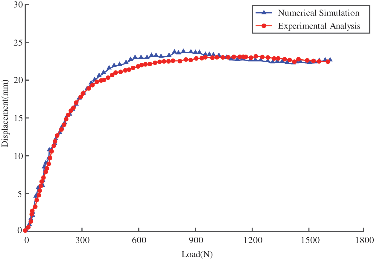
Figure 12: Simulation analysis and test comparison of core plate load-displacement curves
This paper took the wind turbine blade core board as the research object and proposed a modeling method for displacement field variables of heterogeneous materials. Furthermore, it established a heterogeneous solid model of blade core plate, performed finite element analysis on it, and conducted static force tests. The main conclusions are as follows:
(1) The shear modulus of the core board and the glass fiber panel was expressed by establishing a heterogeneous model of the core board of the wind turbine blade. Based on the established model, the finite element method was used to analyze the displayed dynamics, and the failure load of the core plate was 1.62 kN. And the deformation shape of the core board was obtained through simulation.
(2) The failure modes of the core plate included elasticity, yield, and failure stages. In the elastic stage, the deformation of the core board could restore to its original state; in the yield stage, the glass fiber panel yielded, and the core layer near the upper panel was gradually compacted; in the failure stage, the upper panel was partially deformed, and the central area of the core layer was compacted.
(3) The main failure modes of the core board were plastic deformation, core material collapse and delamination of the panel-core material interface. The indenter expanded along the surface-core interface on both sides during delamination, and bending deformation was more likely to occur at the delamination position.
(4) The three-point bending test was verified by building a test platform, and the test measured the damage load of 1.59 kN, with a difference of 1.9%. The load-displacement curve obtained by the numerical simulation was basically consistent with the experimental results, and the finite element analysis’s deformation patterns were consistent with the experimental results. The validity and reliability of the displacement field variable modeling were verified. It has important guiding significance for the design of wind power blades and related structures, and at the same time provides detailed experimental control data for related numerical simulation work.
Funding Statement: This research was funded by National Natural Science Foundation of China (Grant No. 52075305), Natural Science Foundation of Shandong Province (Grant No. ZR2019- MEE076) and Zhoucun District School City Integration Development Project (Grant No. 2020ZCXCZH01).
Conflicts of Interest: The authors declare that they have no conflicts of interest to report regarding the present study.
References
1. Cao, Q., Xiao, L., Cheng, Z., Liu, M. (2021). Dynamic responses of a 10 mw semi-submersible wind turbine at an intermediate water depth: A comprehensive numerical and experimental comparison. Ocean Engineering, 232, 109138. DOI 10.1016/j.oceaneng.2021.109138. [Google Scholar] [CrossRef]
2. Elhenawy, Y., Fouad, Y., Marouani, H., Bassyouni, M. (2021). Performance analysis of reinforced epoxy functionalized carbon nanotubes composites for vertical axis wind turbine blade. Polymers, 13(3), 422–438. DOI 10.3390/polym13030422. [Google Scholar] [CrossRef]
3. Katsaprakakis, D. A., Papadakis, N., Ntintakis, I. (2021). A comprehensive analysis of wind turbine blade damage. Energies, 14(18), 5974–6005. DOI 10.3390/en14185974. [Google Scholar] [CrossRef]
4. Hand, B., Kelly, G., Cashman, A. (2020). Structural analysis of an offshore vertical axis wind turbine composite blade experiencing an extreme wind load. Marine Structures, 75, 102858. DOI 10.1016/j.marstruc.2020.102858. [Google Scholar] [CrossRef]
5. Murray, R. E., Beach, R., Barnes, D., Snowberg, D., Berry, D. et al. (2021). Structural validation of a thermoplastic composite wind turbine blade with comparison to a thermoset composite blade. Renewable Energy, 164, 1100–1107. DOI 10.1016/j.renene.2020.10.040. [Google Scholar] [CrossRef]
6. Wang, J., Huang, X., Wei, C., Zhang, L., Li, C. et al. (2021). Failure analysis at trailing edge of a wind turbine blade through subcomponent test. Engineering Failure Analysis, 130, 105596. DOI 10.1016/j.engfailanal.2021.105596. [Google Scholar] [CrossRef]
7. Alphonse, M., Raja, V., Krishna, V. G., Kiran, R., Chandra, L. (2021). Mechanical behavior of sandwich structures with varying core material–A review. Materials Today: Proceedings, 44(5), 3751–3759. [Google Scholar]
8. Chen, X. (2020). Fractographic analysis of sandwich panels in a composite wind turbine blade using optical microscopy and X-ray computed tomography. Engineering Failure Analysis, 111, 104475. DOI 10.1016/j.engfailanal.2020.104475. [Google Scholar] [CrossRef]
9. Kumar, S. S., Puneet, T. (2018). Heterogeneous modeling based prosthesis design with porosity and material variation. Journal of the Mechanical Behavior of Biomedical Materials, 87, 124–131. DOI 10.1016/j.jmbbm.2018.07.029. [Google Scholar] [CrossRef]
10. Qian, X., Dutta, D. (2004). Feature-based design for heterogeneous objects. Computer-Aided Design, 36(12), 1263–1278. DOI 10.1016/j.cad.2004.01.012. [Google Scholar] [CrossRef]
11. Gustafsson, A., To GnIni, M., Bengtsson, F., Gasser, T. C., Grassi, L. (2020). Subject-specific FE models of the human femur predict fracture path and bone strength under single-leg-stance loading. Journal of the Mechanical Behavior of Biomedical Materials, 113, 104118. DOI 10.1016/j.jmbbm.2020.104118. [Google Scholar] [CrossRef]
12. Yang, J. R., Jia, Q. H., Chen, G. L., Wang, G. C. (2010). Review on modeling technologies of heterogeneous composite material structure and development tendency. Coal Mine Machinery, 2010, 31(8), 19–22. [Google Scholar]
13. Hao, W., Fan, H., Han, C., Li, S. (2016). Finite element analysis of smart wind turbine blades sandwiched with magnetorheological fluid. Journal of Vibroengineering, 18(6), 3858–3868. DOI 10.21595/jve.2016.16802. [Google Scholar] [CrossRef]
14. Bornassi, S., Navazi, H. M., Haddadpour, H. (2020). Coupled bending-torsion flutter investigation of mre tapered sandwich blades in a turbomachinery cascade. Thin-Walled Structures, 152, 106765. DOI 10.1016/j.tws.2020.106765. [Google Scholar] [CrossRef]
15. Biswas, A., Shapiro, V., Tsukanov, I. (2004). Heterogeneous material modeling with distance fields. Computer Aided Geometric Design, 21(3), 215–242. DOI 10.1016/j.cagd.2003.08.002. [Google Scholar] [CrossRef]
16. Zaharia, S. M., Enescu, L. A., Pop, M. A. (2020). Mechanical performances of lightweight sandwich structures produced by material extrusion-based additive manufacturing. Polymers, 12(8), 1740–1759. DOI 10.3390/polym12081740. [Google Scholar] [CrossRef]
17. Lahuerta, F., Koorn, N., Smissaert, D. (2018). Wind turbine blade trailing edge failure assessment with sub-component test on static and fatigue load conditions. Composite Structures, 204, 755–766. DOI 10.1016/j.compstruct.2018.07.112. [Google Scholar] [CrossRef]
18. Peeters, M., Santo, G., Degroote, J., Paepegem, W. V. (2018). High-fidelity finite element models of composite wind turbine blades with shell and solid elements. Composite Structures, 200, 521–531. DOI 10.1016/j.compstruct.2018.05.091. [Google Scholar] [CrossRef]
19. Willberg, C., Ravi, R., Rieke, J., Heinecke, F. (2021). Validation of a 20 m wind turbine blade model. Energies, 14(9), 2451–2499. DOI 10.3390/en14092451. [Google Scholar] [CrossRef]
20. Fries, T. P., Ba Ydoun, M. (2012). Crack propagation with the extended finite element method and a hybrid explicit-implicit crack description. International Journal for Numerical Methods in Engineering, 89(12), 1527–1558. DOI 10.1002/nme.3299. [Google Scholar] [CrossRef]
21. Belytschko, T., Black, T. (1999). Elastic crack growth in finite elements with minimal remeshing. International Journal for Numerical Methods in Engineering, 45(5), 601–620. DOI 10.1002/(ISSN)1097-0207. [Google Scholar] [CrossRef]
22. Pan, L., Zhu, Z., Xiao, H., Wang, L. (2021). Numerical analysis and parameter optimization of j-shaped blade on offshore vertical axis wind turbine. Energies, 14(19), 1–29. DOI 10.3390/en14196426. [Google Scholar] [CrossRef]
23. Huang, Z., Wang, X., Wu, N., Chu, F., Luo, J. (2019). A finite element model for the vibration analysis of sandwich beam with frequency-dependent viscoelastic material core. Materials, 12(20), 3390–3404. DOI 10.3390/ma12203390. [Google Scholar] [CrossRef]
24. Al-Saadi, A. U., Aravinthan, T., Lokuge, W. (2019). Effects of fibre orientation and layup on the mechanical properties of the pultruded glass fibre reinforced polymer tubes. Engineering Structures, 198, 109448. DOI 10.1016/j.engstruct.2019.109448. [Google Scholar] [CrossRef]
25. Madenci, E., Zkl, Y. O., Gemi, L. (2020). Experimental and theoretical investigation on flexure performance of pultruded GFRP composite beams with damage analyses. Composite Structures, 342, 112162. DOI 10.1016/j.compstruct.2020.112162. [Google Scholar] [CrossRef]
26. Rafiee, R., Hashemi-Taheri, M. R. (2020). Failure analysis of a composite wind turbine blade at the adhesive joint of the trailing edge. Engineering Failure Analysis, 121, 105148. DOI 10.1016/j.engfailanal.2020.105148. [Google Scholar] [CrossRef]
Cite This Article
 Copyright © 2023 The Author(s). Published by Tech Science Press.
This work is licensed under a Creative Commons Attribution 4.0 International License , which permits unrestricted use, distribution, and reproduction in any medium, provided the original work is properly cited.
 Downloads
 Citation Tools