
 Submit a Paper
 Propose a Special lssue
 Open Access
ARTICLE

Tubular Heat Enhancement Using Twisted Tape Inserts with Large Holes
Faculty of Engineering - Al-Mussayib, University of Babylon, Hilla, Babylon, 15001, Iraq
* Corresponding Author: Ali Jaber Abdulhamed. Email:
Energy Engineering 2024, 121(2), 273-290. https://doi.org/10.32604/ee.2023.045583
Received 31 August 2023; Accepted 25 October 2023; Issue published 25 January 2024
 View Full Text
 Download PDF
Abstract
Heat augmentation techniques play a vital role in the heating and cooling processes in industries, including solar collectors and many applications that utilize heat exchangers. Several studies are based on inserting fillers inside the tubes to enhance heat transfer. This investigation considered the effects of twisted tapes with large holes on a tubular heat exchanger’s (HX) heat transmission, pressure drop, and thermal boosting factor. In the experimental section, counter-swirl flow generators used twisted tapes with pairs of 1.0 cm-diameter holes and changes in porosity (Rp) at 1.30% and 2.70%. In the experiments, air was utilized as a working fluid in a tube with a circular cross-section. The turbulent flow was considered, with Reynolds numbers (Re) domain from 4800 to 9500, and a boundary condition with a uniform wall heat flux was constructed. The findings expound that when the number of holes rose, the Nusselt number (Nu), the factor of friction (f), and the thermal enhancement factor (η) all increased as well. Additionally, as the friction factor increased, the Nusselt number of the tape-equipped tube was noticeably higher. Additionally, it was discovered that the friction factor was between 70% and 94% lower than the values of the tube without tape, while the (Nu) was between 87% and 97% higher than the conventional tube values. The maximum value of η is 89%. According to the experimental results, empirical correlations for Nu, f, and η were also generated.Keywords
Nomenclature
| A | Cross-sectional area m2 |
| D | Tube diameter m |
| Cp | Specific heat capacity kJ/kg·s |
| f | Friction factor |
| h | Heat transfer coefficient W/m2°C |
| L | Length m |
| k | Thermal conductivity W/m·K |
| m. | Mass flow rate Kg/s |
| Nu | Nusselt number |
| T | Temperature °C |
| I | Current Amperes |
| Porosity of the tape % | |
| V | Voltage volt |
| V˙ | Volumetric flow rate m3/s |
| P | Length of the single twist m |
| Pr | Prandtl number |
| Q | The rate of heat transfer W |
| q | The rate of heat transfer W/m2 |
| Re | Reynolds number |
| u | Air velocity m/s |
| X | Wetted perimeter m |
| y | Twist ratio |
| ρ | Density Kg/m3 |
More effort is being made to manufacture high-performance heat exchanger (HX) equipment due to rising energy demand’s high material and energy costs. In HX systems, heat transfer augmentation techniques are widely employed to improve heat transfer and boost thermal performance. One of the more favorable techniques, and one that has been frequently used for improving heat transmission, is the insertion of a swirl generator made of twisted tape. The swirl generator or twisted tape reduced the thermal boundary layer thickness, which increased heat transfer by convective. It can be inferred that the smaller boundary layer is caused by the turbulence and vortex motion that these tapes produce. Twisted tape inserts have been widely applied in engineering purposes such as heat recovery procedures, refrigeration, air-conditioning A/C systems, as well as chemical reactors as a continuous swirl flow technique to improve heat exchange efficiency in heat exchanger (HX) devices. The pumping power and the friction inside the tube fitted with the twisted tape insert are unavoidably raised due to the increased heat transfer, which inevitably increases the pumping cost. Consequently, it is difficult to create a twisted tape that meets the need for excellent improvement in heat transfer with a suitable pressure reduction, which reduces energy use [1–4].
Twisted tapes have been extensively studied to enhance heat transfer in HXs for several years. To facilitate the mixing of the fluid between the core region and the area close to the wall, the tape with twist is frequently used in tube HXs. Several documented experimental investigations have looked into the impact of different inserts on the evaluation of tube performance [1,3,5]. Twisted tapes were also employed with other heat exchange boosting techniques, commonly called compound devices, to improve heat transfer. There are several examples of tubes that are equipped with twisted tape, including Conical ring inserts [6], dimpled tubes [7], converging-diverging tubes [8], spirally grooved tubes [9], helical-ribbed tubes [10], corrugated tubes combined with twisted tape.
However, a substantial study has been done to increase their performance compared to the standard one by altering the inserted tapes with twisted to produce more flow disturbance. These studies sought the ideal balance between heat spread and fluid friction inside the upgraded systems for various applications [2,11,12]. Experimental research on the thermal properties of serrated tapes with a twist [13] with different axes and center wings [14] was conducted in a circular tube. Wongcharee et al. [4] discussed the impacts of tapes with twists with rotating axes and wings on heat transfer, friction due to the flow, and the characteristics of the thermal performance in a circular pipe. The findings showed that all twisted tapes consistently had elevated heat transfer rates and factors of friction than those without tape with twisted. The thermal and the pressure values were examined in an experimental tube with two twisted tape components [3].
Simth et al. [1] conducted tests to interpret the effects of twin-counter/co-twisted tapes on heat transport, friction factor, and thermal enhancement index (TEI). The outcomes showed that the twin counter-twisted tapes were superior to those improving heat transmission. A comparison study of thermal and hydraulic calculations in circular tubes equipped with single, twin, and triple twisted tapes was published by Chang et al. [15]. The findings showed that as the quantity of twisted tape inserts rose, the heat transfer enhancement also increased. Bhuiya et al. [16] conducted an experimental study to see how much heat would pass through a tube with punctured twisted tape inserts. According to the study, the twisted tape inserts with holes boosted the heat exchange rate at the expense of the power of the blower. The heat transfer rates associated with combination approaches or modified twisted tapes have typically been observed to be greater than those provided by conventional twisted tapes. To accomplish enhanced transfer of the heat results with a manageable pressure and drop, researchers must adapt twisted tapes with the proper geometries, which is a difficult operation [16]. In more recent studies, Harish et al. [17] conducted an examination numerically for the flow characteristics of a steady heat flux-wall tube with laminar flow in three dimensions. Circular protruded twisted-tape configurations were examined, with a twist ratio of 3.0. These geometries yielded a maximum thermal enhancement factor roughly 1.5 times higher than that achieved with conventional twisted tape. When comparing Nusselt numbers and friction factors concerning Reynolds numbers, the test data revealed a 15%–24% increase in Nusselt numbers and a 12%–22% growth in friction factor compared to the Plain tube. Fazel et al. [18] used a wavy passage with twisted tape installed to conduct a numerical study. The simulation was carried out by changing Re No. from 2500 to 10500 with 2000 steps, and the tube has indication angles of 15° and 30° with twist angles of 90° and 180°. The same results that Harish et al. [17] reported were items of performance improvement. All the case data showed improvement in the performance; however, the case with an inclination angle equal to 30° at Re = 8500 and 10500 showed inefficient behavior.
A twisted elliptical tube was used to analyze its performance in heat transfer [19]. A twisted insert was integrated inside the tube. The outcomes showed at Reynolds number of 1000; there is a rise in the Nu and f by 123.9% and 131.9% compared to the conventional case. A study utilizing a water/CuO nanofluid and both straight and twisted tape configurations with rods inserted has been performed by Dagdevir et al. [20]. The experimentation encompassed Reynolds numbers from 5000 to 29,000, nanofluid mass fractions of 0.0%, 1.0%, and 2.0%, and various pitch ratios (L/p) of the rods installed on the 10, 20, and 40 tapes. The best results were reached at the mass fraction of the nanofluid of about 2.0% at a Reynolds number of about 6500.
From the works mentioned above, it can be noted that different researchers’ works focused on the effect of the various types of inserts with large numbers. However, the effect of only a few numbers of relatively large holes twisted tape inserts impact was not considered. Therefore, this study suggests a newly developed twisted tape with a relatively small number of holes for improving heat transfer. Moreover, several studies focused on using liquid to flow inside the tube; however, air and gas heat exchanger plays an essential role in several applications that deal with heat loss, such as diesel engines and heat recovery systems [21–24]. Additionally, it examined how the counter-swirling flow produced by the tapes affects the efficiency of thermal enhancement, the friction factor, and the augmentation of heat transmission between air and the tube walls. The produced data will establish an empirical correlation of thermal exchange, the factor of friction, and thermal enhancement efficiency.
In both situations (conventional tube and tube coupled with punched twisted tape), the experiment data were utilized to determine the Nu, f, and thermal performance characteristics for a range of Reynolds numbers in the flow area of the tested tube. The following equation was utilized for this aim. For the Mass flow rate calculation, Eq. (1) was used. Where
The average system heat is calculated (Eq. (6)), which represents the net heat input by the electrical heater and the heat received by the fluid, and the heat flux was estimated by Eq. (7). Where
Nusselt number for the area was calculated using Eq. (10).
The average value of Nusselt number was determined in the manner shown below:
The friction factor was expressed:
where
Calculation of
where the
The porosity of the tape was estimated by:
where
The ratio of the twist refers to the ratio of the length to the width of the tape.
where pitch
The experimental design involved an inlet, test tube, air compressor, and cooling system. Fig. 1 shows the experimental rig. The system entrance was made as a paper suggested by Ower et al. [26] to prevent the flow’s stratification and separation.
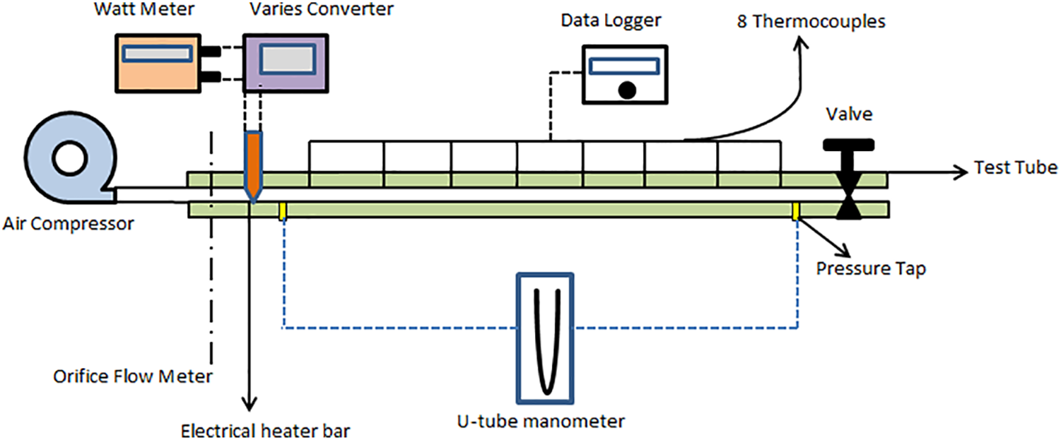
Figure 1: Schematic diagram for the experimental setup
Figs. 2a and 2b show the twisted tape geometry. Stainless steel was used to make the plain tube (test part) with an inside and diameter of the outside surface of 50 and 1000 mm of length. The tape material is stainless steel; it has different porosities.
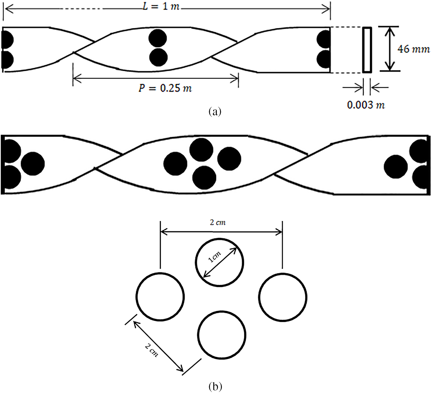
Figure 2: Sketch of the holes’ location and arrangement
An air compressor was used as a source to supply the tube with air see Fig. 3, and it was connected to the tube with an air hose. In addition, the tube was provided with one thermal heater to guarantee the entry of hot air into the tube. A 220-volt and 20-amper thermal heater was used as a heat supply fixed in the anterior side of the tube. It is a glow plug type which is used in diesel engines. An evaporative cooling system was used to cool the tube from the outside.
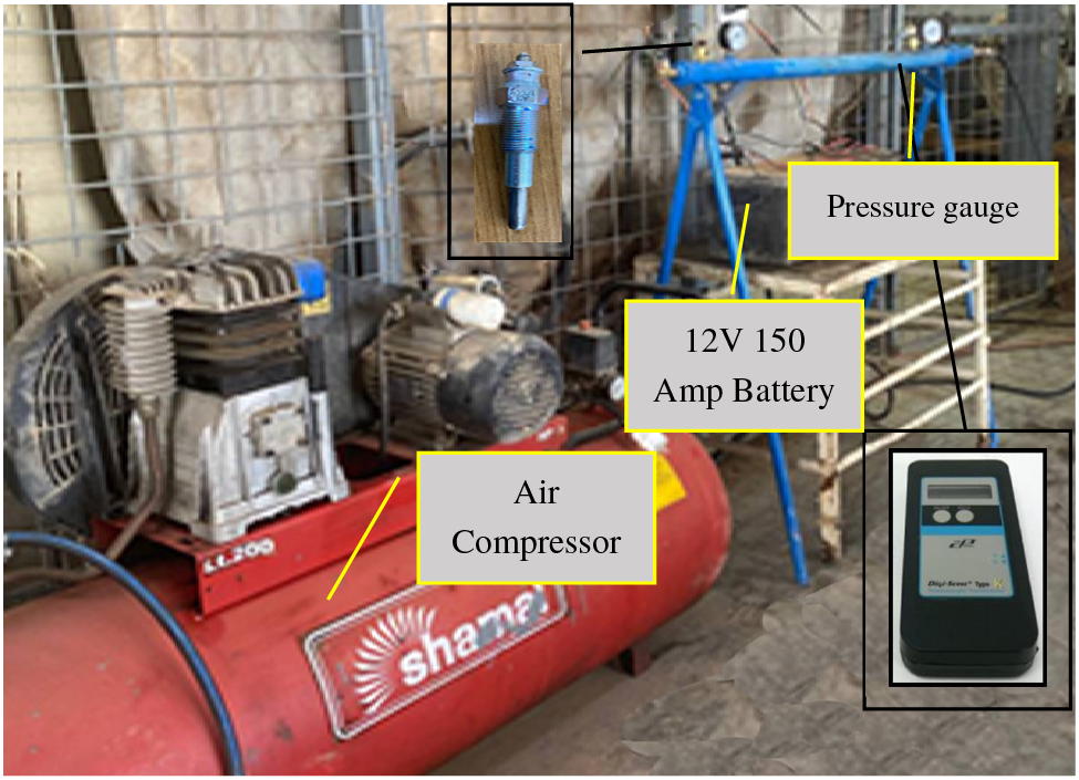
Figure 3: Experimental setup
A k-type thermocouple was tapped in the middle length of the tube wall to record the local temperatures. Two other thermocouples were positioned at the tube inlet and outlet side to quantify the bulk air temperature. All thermocouples were connected to a Ten-Channels Switchbox and then connected with Digi-Sense 91000-00 type K Data Logger as shown in Fig. 3. An inclined U-tube manometer was utilized to gauge the pressure difference across the tube. An anemometer device was utilized to gauge the flow rates across the tube segment and the wind speed. Experimental tests were achieved for the Reynolds number range from 4800–9500.
Some assumptions were made to eliminate the impact of some variables to meet the objectives of the work. These were:
1. The fluid parameters were computed at the Tb values (local bulk temperature) and ambient pressure.
2. Convection heat exchange from the wall of the tube’s interior and the fluid was the only mechanism of heat transmission considered. However, there were places where the inserts and the tube’s inner wall came into contact. As a result, conduction-based heat transmission through the inserts was a possibility.
The data was categorized into four groups based on four flow velocity cases (3.0, 4.6, 5.3, and 6.0 m/s), retaining all other parameters constant. Four tests were done on the system considering the tube without the insert and with it (for two and four holes). For a flow velocity of 6.0 m/s, the results showed that the external surface temperature of the tube decreased with time from 140°C to 105°C until it started to level up at 103°C (Fig. 4). It can be noted that the tube equipped with (twisted tape plus four holes) has higher efficiency than that with (twisted tape plus two holes), twisted tape without holes, and plain tube, respectively (Fig. 4). More additional surface temperature reduction with the flow velocity increase (Figs. 5–7). Furthermore, it can be seen that the data start to level up at almost the same temperature for these last velocity ranges, at about 95°C. In all the cases, the insert with four holes performs better than the one without, with two holes in temperature exchange.
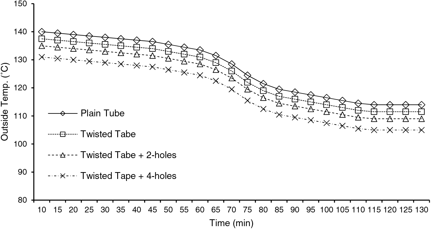
Figure 4: Tube’s external surface temperature with time at
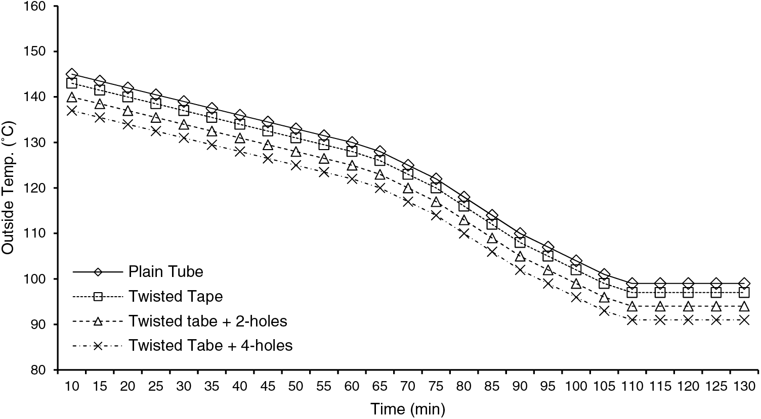
Figure 5: Tube’s external surface temperature with time at
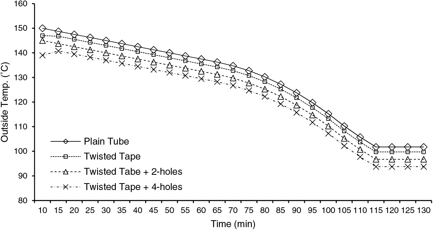
Figure 6: Tube’s external surface temperature with time at
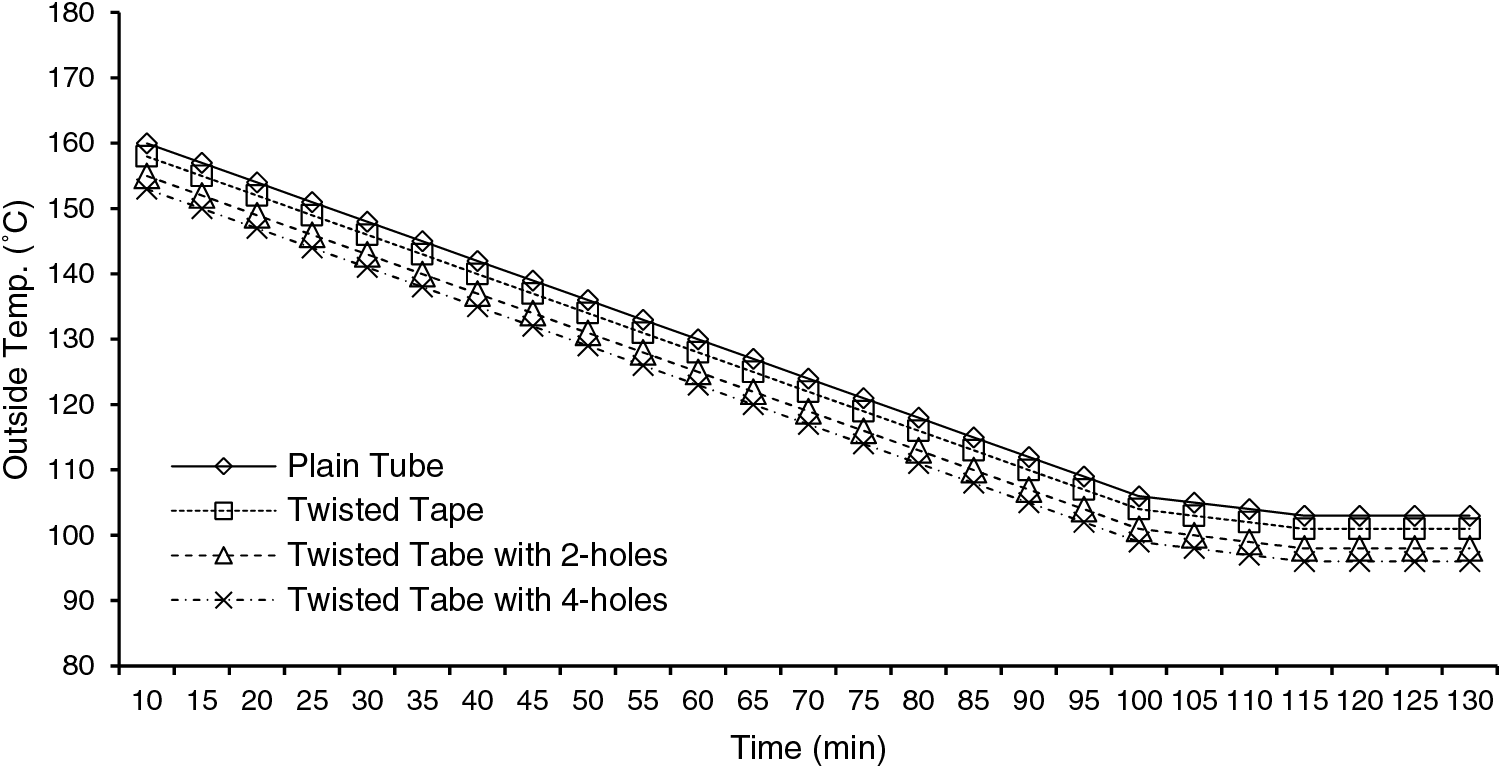
Figure 7: Tube’s external surface temperature with time at
The results show that as the internal flow velocity increases, there is a delay in the cooling process of the tube. For instance, at u = 3.0 m/s, the curve for all the configurations starts to level up at 80 min of a run; however, at u = 6.0 m/s, the temperature becomes almost constant after 100 min, as shown in Figs. 4–7. This is related to the high heat exchange rate between the inlet airflow and the tube surface.
4.2 Impact of the Number of Holes on the Thermal Behavior of the System
4.2.1 Verification of the Results
The experimental findings of the punched twisted tapes fitted to the tube regarding heat transmission, friction factor, and efficiency thermal enhancement behavior were first verified against those made using the standard correlations for the clear tube. Afterward, the verified data were compared with the modified tube cases. The friction factor was compared with the Petukhov model [27], and the heat transfer rate was expressed as a Nusselt number for plain tubes, which was verified with the correlations from the previous work of Gnielinski [28]. Figs. 8a and 8b show the results of verification checks on the heat transmission and the factor of friction in the tube without inserts, respectively. The data relating to the current empty tube are in acceptable discrepancy compared to the earlier correlations for the Nu. Number and factor of friction, within
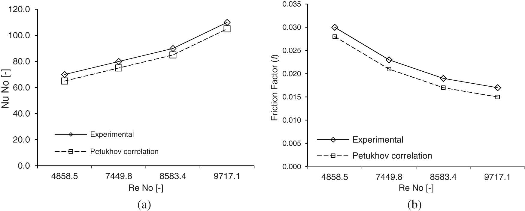
Figure 8: Comparison between the measured data and correlated models (from previous work) of heat transmission and factor of the friction in the conventional tube
4.2.2 Impact of the Twisted-Perforated Tapes
Fig. 9a shows a general trend showing that Nusselt number (Nu) decreased, so Re (Reynolds number) rose. This is assigned to the increase in the convective heat transfer when the Reynolds number decreases due to an increase in the tested tube’s exposure time to the outside airflow. For the entire range of Reynolds numbers, installing the twisted tape swirl generators substantially impacts the rate of heat movement. Commonly, a tape with twisted inserts produced a secondary, longer path for a flow with swirls or the flow of the fluid inside the tube. The entire length of the twisted tape functioned as an uninterrupted spinning flow throughout the test tube’s length to increase the flow’s residence time. The generated swirl flow increases the fluid velocity close to the wall and reduces it at the core; this will decrease the thickness of the thermal boundary layer and enhance the mixing of the flow [5]. Moreover, the flow velocity and boundary layer thickness were both increased because of the swirl flow. The boundary layer separation occurs due to the interaction with the swirl created by the twist in the tape inserts. The increase in the flow turbulence resulting from the presence of the swirls produced an augmented heat transfer based on the convection mechanism. This is attributed to the lengthening of the flow’s residence time due to its division into two streams with enhanced fluid mixing between the core flow and the tube walls, achieved by increasing the turbulence flow intensity [7]. The holes also play a significant role in increasing the mixing between both channels of the flow. This is attributed to the effect of the force that is generated over the tape surface, which enables flow exchange between both sides of the tape [29]. The results showed that the heat transfer rates produced by the perforated twisted tape were 87% higher than the plain tube data. The ratio of Nusselt number
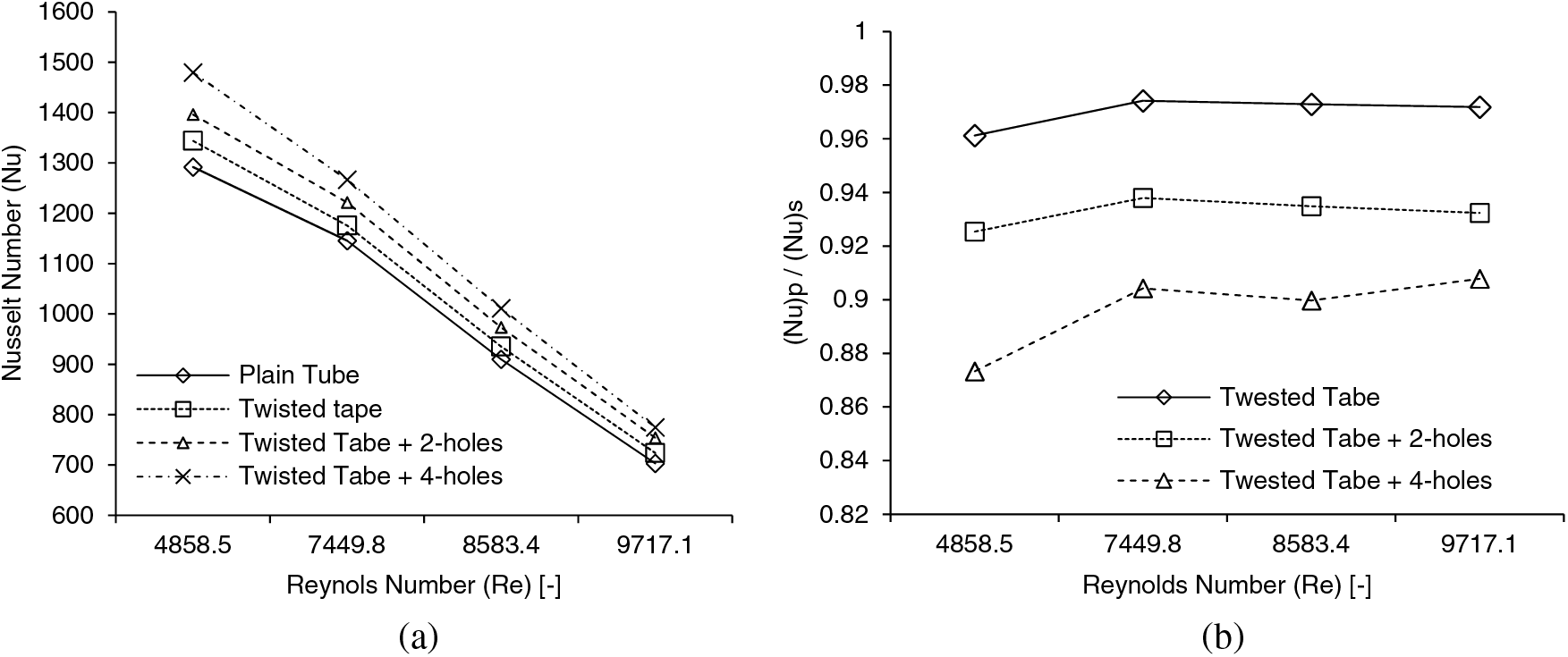
Figure 9: Nusselt number and its ratio variation with Re: (a) Nu and (b)
Installing the tape with a punched twist reduces the friction factor (f) (Fig. 10a). Furthermore, it can be observed that the friction factor tends to follow the same tendency for both the tube without insert and the tube with inserts. Moreover, the increase in Reynolds number caused a reduction in the friction factor lower values of the Re number, which related to lower flow rates; air could move all over the tape and produce strong forces due to the frictional because there were little vortices there, to begin with, tape inserts with a twist over a simple tube would improve heat transmission. Compared to the basic tube, the friction factors of tubes installed with tape with a single twist, tape with twisted and two holes, and tape with a twist and four holes were around 70% and 92% lower, respectively [28]. Moreover, the tube with a larger number of holes has a higher reduction in the factor of friction as compared with the tape with two holes.
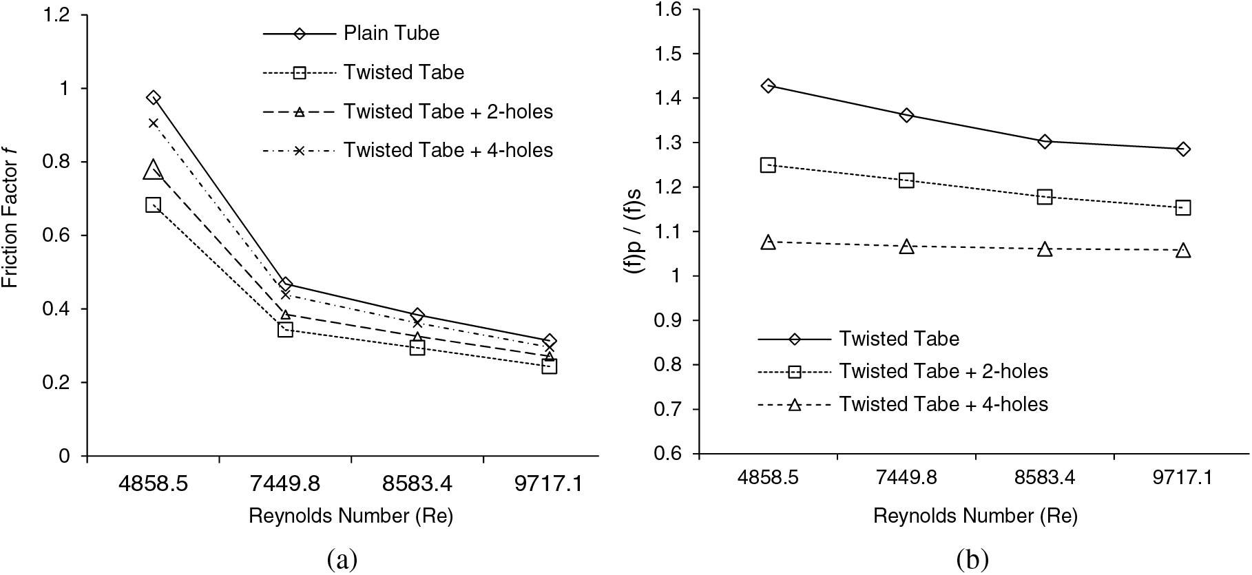
Figure 10: Friction factor and its ratio variation with Re: (a) f and (b)
The impact of porosities (1.3% and 2.7%) on the rate of the transfer of the heat of the tube modified with holed tapes with a twist is shown in Figs. 9a and 9b. The experimental findings showed an improved heat transfer rate augmented as the number of holes was added. This occurred because of the large diameter of holes, which increases the fluid flow’s swirling influence and was explained by reference [30]. Additionally, there is an increase in the swirl intensity at 2.70% porosity, resulting in a further effective break of the boundary layer throughout the channel flow produced due to the presence of the tape. Therefore, heat is effectively transferred over a thin boundary layer, increasing the flow’s residence time. For the examined range of porosity, the twisted tape inserts with 2.70% porosity had a better heat transmission rate than the tubes with no perforations or plain tubes.
The value of f of the tape insert-fitted tube was observed to be higher than the empty tube. The increased surface area led to increase the intensity of the swirl, flow obstruction, and lost dynamic pressure of the flow due to the reduction in the viscosity of the fluid layers attached to the wall of the tube were the key causes of the higher friction loss as supported by reference [31]. Furthermore, pressure loss occurred because of the boundary layer’s inertial and pressure forces interaction. The ratio friction factor (
The factor of friction is also affected by the porosity, it can be seen in Figs. 10a and 10b; the factor of friction and its ratio tend to increase with the number of holes reduction. This is attributed to increasing turbulence flow intensity when a tape with a single twist and four holes (2.70% porosity) was used. Therefore, the holes in the twisted tape led to swirls and, at the same time, reduced the friction between the fluid and the twisted tape. To conclude, using a large size and a small number of holes in twisted tape produced higher efficiency than using a large number and small size of holes, as presented by Bhuiya et al. [32].
4.3 Assessment of the System’s Performance
A fixed velocity of the flow comparison was made to assess the increased efficiency of the heat move of the tube combined with a tape with a single twist and holes. Eq. (19) demonstrates how the pressure drop between a regular tube and a tube with an insert relates to the volumetric flow rate at constant flow velocity [10]. The correlation that relates Reynolds number with the friction factor is presented in Eqs. (20) and (21).
Or
The friction factor to the Nusselt number ratio at constant airflow velocity is the thermal enhancement efficiency (
The evaluation of the performance is accounted for to evaluate the gains of modifying the tube with interesting tapes in terms of efficiency improvement. The Reynolds number (
The rate of heat transfer and the factor of friction values for tube with and without the tape were instantaneously evaluated at constant air velocity using Eq. (22). The improvement in heat transfers due to the installation of the perforated tapes with a twist with two and four holes (1.30% and 2.70%) showed ad Re number increases the efficiency increase, Fig. 11, for all the cases. The tube modified with inserts at a higher Re offered better thermal augmentation efficiency, as predicted in Fig. 11. At a constant velocity of the flow through the tube, Eiamsa-ard et al. [6,36] reported thermal enhancement efficiencies by 1.40% and 1.10% using twisted tapes and entire-length tape with a twist, respectively. According to the experiment's findings, using 4-hole tubes with porosity (
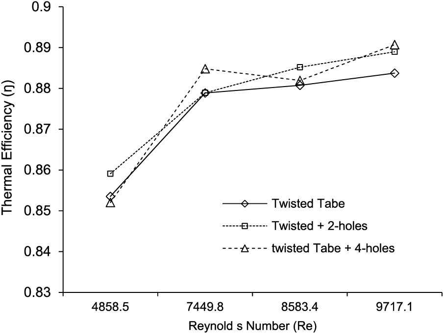
Figure 11: Thermal efficiency compared with Reynolds number for all the cases at constant flow velocity
The selected working fluid was in the current analysis, and the investigations were done in a tube with homogenous heat flux. Correlations that relate Reynolds numbers (4800 to 9500) and porosities (1.20% to 2.70%) were developed. The porosity (
The tube with tape thermal efficiency that has holes and twists can be calculated using Eqs. (17), (21), (23), and (24).
where:
And
Figs. 12–14 present the Nu, f, and thermal enhancement efficiency that is calculated using Eqs. (24)–(26). These data were compared to the one found from the measurements extracted from the experiment. An acceptable agreement was observed from the comparison with discrepancies of about
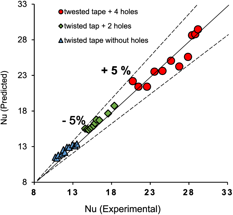
Figure 12: Correlation of the Nusselt number
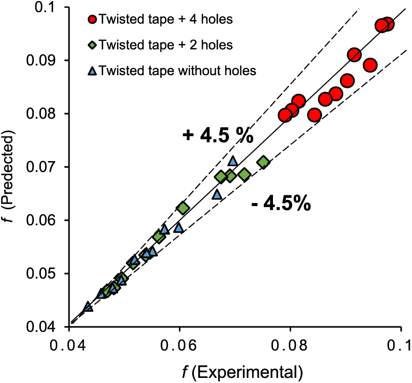
Figure 13: Correlation of the friction factor
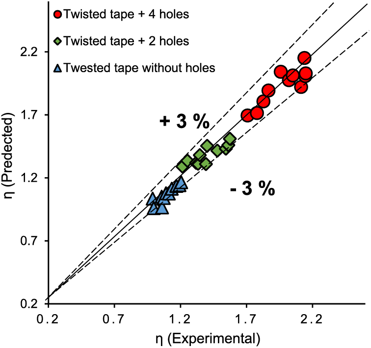
Figure 14: Correlation of the thermal enhancement efficiency
Kline et al.’s approach [37] was used to determine the uncertainty in the experimental measurements. The required variables were calculated concerning the separated experimental data and correlated with the established uncertainties using the uncertainty calculation method. The Re number, Nu number, and f were determined with a maximum error of 1.80%, 2.80%, and 3.50%, respectively.
A circular cross-sectional tube combined with punched tape with twist inserts with 1.30% and 2.7% porosity was explored through an experiment in the turbulent flow regime, Re No. = 4800 to 9500 and air as a working fluid. The main outcomes can be summed up as below:
• The holed twisted tape significantly improved heat transfer, friction factor, and thermal enhancement efficiency, especially as the number of holes increased.
• The factor of friction for the tube with porous tape with a twist inserts was 70% to 94% less than that for the tube without any tape at the unchanged Reynolds number, and the Nusselt number was reached at values 87% to 97% higher. Additionally, for all Reynolds numbers, the influence of porosity of 2.7% was more prominent.
• The modified by holes single counter twisted tape inside the tube improved the thermal efficiency by 89% at constant blowing power.
• The data Nusselt number, factor of friction, and efficiency of thermal enhancement gathered from experimental work were used to build an empirical correlation. The derived correlations with small deviations with the experimental data of +5.0%, +4.5%, and +3.0%, respectively.
• The presence of the tape generated a swirl flow that increased the fluid velocity close to the wall and reduced it at the core, decreasing the thickness of the thermal boundary. Moreover, the holes also play a significant role in increasing the mixing between both flow channels.
• The effect of only a few relatively large holes in the tape with a twist insert on the flow behavior and heat transfer is considerable. Furthermore, the produced correlation agrees with the experimental data and can be utilized to predict the efficiency at the early stage of heat exchanger or heat recovery device design.
Acknowledgement: None.
Funding Statement: The authors received no specific funding for this study.
Author Contributions: The authors confirm their contribution to the paper as follows: study idea and the design of the system: Ali Jaber Abdulhamed; experimental work and the collection of data: Ali Jaber Abdulhamed and Aws Al-Akam; examination and interpretation of data: Ali Jaber Abdulhamed and Aws Al-Akam, manuscript preparation: Wisam J. Khudhayer and Ali Sabri Allw. All authors reviewed and approved the final version of the manuscript.
Availability of Data and Materials: All the data and materials are available at request.
Conflicts of Interest: The authors declare that they have no conflicts of interest to report regarding the present study.
References
1. Smith, E., Chinaruk, T., Petpices, E., Pongjet, P. (2009). Convective heat transfer in a circular tube with short-length twisted tape insert. International Communications in Heat and Mass Transfer, 36, 365–371. https://doi.org/10.1016/j.icheatmasstransfer.2009.01.006 [Google Scholar] [CrossRef]
2. Eiamsa-ard, S., Thianpong, C., Eiamsa-ard, P. (2010). Turbulent heat transfer enhancement by counter/co-swirling flow in a tube fitted with twin twisted tapes. Experimental Thermal Fluid Science, 34(1), 53–62. https://doi.org/10.1016/j.expthermflusci.2009.09.002 [Google Scholar] [CrossRef]
3. Eiamsa-ard, S., Thianpong, C., Eiamsa-ard, P., Promvonge, P. (2010). Thermal characteristics in a heat exchanger tube fitted with dual twisted tape elements in tandem. International Communications in Heat and Mass Transfer, 37, 39–46. https://doi.org/10.1016/j.icheatmasstransfer.2009.08.010 [Google Scholar] [CrossRef]
4. Wongcharee, K., Eiamsa-ard, S. (2011). Heat transfer enhancement by twisted tapes with alternate-axes and triangular, rectangular and trapezoidal wings. Chemical Engineering and Processing: Process Intensification, 50, 211–219. https://doi.org/10.1016/j.cep.2010.11.012 [Google Scholar] [CrossRef]
5. Bhuiya, M. M. K., Chowdhury, M. S. U., Ahamed, J. U., Khan, M. J. H., Sarkar, M. A. R. et al. (2012). Heat transfer performance for turbulent flow through a tube using double helical tape inserts. International Communications in Heat and Mass Transfer, 39, 818–825. https://doi.org/10.1016/j.icheatmasstransfer.2012.04.006 [Google Scholar] [CrossRef]
6. Promvonge, P., Eiamsa-ard, S. (2007). Heat transfer behaviors in a tube with combined conical-ring and twisted-tape insert. International Communications in Heat and Mass Transfer, 34, 849–859. https://doi.org/10.1016/j.icheatmasstransfer.2007.03.019 [Google Scholar] [CrossRef]
7. Thianpong, C., Eiamsa-ard, P., Wongcharee, K., Eiamsa-ard, S. (2009). Compound heat transfer enhancement of a dimpled tube with a twisted tape swirl generator. International Communications in Heat and Mass Transfer, 36, 698–704. https://doi.org/10.1016/j.icheatmasstransfer.2009.03.026 [Google Scholar] [CrossRef]
8. Hong, M., Deng, X., Huang, K., Li, Z. (2007). Compound heat transfer enhancement of a converging-diverging tube with evenly spaced twisted-tapes. Chinese Journal of Chemical Engineering, 15, 814–820. https://doi.org/10.1016/s1004-9541(08)60008-7 [Google Scholar] [CrossRef]
9. Bharadwaj, P., Khondge, A. D., Date, A. W. (2009). Heat transfer and pressure drop in a spirally grooved tube with twisted tape insert. International Communications in Heat and Mass Transfer, 52, 1938–1944. https://doi.org/10.1016/j.ijheatmasstransfer.2008.08.038 [Google Scholar] [CrossRef]
10. Promvonge, P., Pethkool, S., Pimsarn, M., Thianpong, C. (2012). Heat transfer augmentation in a helical-ribbed tube with double twisted tape inserts. International Communications in Heat and Mass Transfer, 39, 953–959. https://doi.org/10.1016/j.icheatmasstransfer.2012.05.015 [Google Scholar] [CrossRef]
11. Eiamsa-ard, S., Wongcharee, K., Eiamsa-ard, P., Thianpong, C. (2010). Heat transfer enhancement in a tube using delta-winglet twisted tape inserts. Applied Thermal Engineering, 30, 310–318. https://doi.org/10.1016/j.applthermaleng.2009.09.006 [Google Scholar] [CrossRef]
12. Murugesan, P. K., Mayilsamy, K., Suresh, S., Srinivasan, P. (2011). Heat transfer and pressure drop characteristics in a circular tube fitted with and without V-cut twisted tape insert. International Communications in Heat and Mass Transfer, 38, 329–334. [Google Scholar]
13. Eiamsa-Ard, S., Promvonge, P. (2010). Thermal characteristics in a round tube fitted with serrated twisted tape. Applied Thermal Engineering, 30, 1673–1682. https://doi.org/10.1016/j.applthermaleng.2010.03.026 [Google Scholar] [CrossRef]
14. Eiamsa-ard, S., Wongcharee, K., Eiamsa-ard, P., Thianpong, C. (2010). Thermohydraulic investigation of turbulent flow through a round tube equipped with twisted tapes consisting of center wings and alternate axes. Experimental Thermal Fluid Science, 34, 1151–1161. https://doi.org/10.1016/j.expthermflusci.2010.04.004 [Google Scholar] [CrossRef]
15. Chang, S. W., Yu, K. Lu M. H. (2005). Heat transfers in tubes fitted with single, twin, and triple twisted tapes. Experimental Heat Transfer, 18(4), 279–294. https://doi.org/10.1080/08916150500201560 [Google Scholar] [CrossRef]
16. Bhuiya, M. M. K., Chowdhury, M. S. U., Saha, M., Islam, M. T. (2013). Heat transfer and friction factor characteristics in turbulent flow through a tube fitted with perforated twisted tape inserts. International Communications in Heat and Mass Transfer, 46, 49–57. https://doi.org/10.1016/j.icheatmasstransfer.2013.05.012 [Google Scholar] [CrossRef]
17. Harish, H. V., Manjunath, K. (2022). Heat and fluid flow behaviors in a laminar tube flow with circular protruded twisted tape inserts. Case Studies in Thermal Engineering, 32, 101880. [Google Scholar]
18. Fazel, Z., Sadrhosseini, H., Kazemzadeh, S. (2022). Heat transfer intensification of turbulent forced convection by inserting discontinuous twisted tapes in a wavy tube; hydrothermal and thermodynamics analysis. Chemical Engineering and Processing-Process Intensification, 181, 109137. [Google Scholar]
19. Mashayekhi, R., Eisapour, A. H., Eisapour, M., Talebizadehsardari, P., Rahbari, A. (2021). Hydrothermal performance of twisted elliptical tube equipped with twisted tape insert. International Journal of Thermal Sciences, 172, 107233. https://doi.org/10.1016/j.ijthermalsci.107233 [Google Scholar] [CrossRef]
20. Dagdevir, O., Ozceyhan, V. (2022). A comprehensive second law analysis for a heat exchanger tube equipped with the rod inserted straight and twisted tape and using water/CuO nanofluid. International Journal of Thermal Sciences, 181, 107765. https://doi.org/10.1016/j.ijthermalsci.2022.107765 [Google Scholar] [CrossRef]
21. Liu, Z., Liu, J. (2022). Investigation of the effect of altitude on in-cylinder heat transfer in heavy-duty diesel engines based on an empirical model. Journal of Energy Resources Technology, 144(11), 112303. https://doi.org/10.1115/1.4054136 [Google Scholar] [CrossRef]
22. Sun, M., Liu, Z., Liu, J. (2023). Numerical investigation of the intercooler performance of aircraft piston engines under the influence of high altitude and cruise mode. ASME Journal of Heat and Mass Transfer, 145(6), 062901. https://doi.org/10.1115/1.4055941 [Google Scholar] [CrossRef]
23. Liu, Z., Liu, J. (2021). Experimental investigation of combustion characteristics of a single cylinder diesel engine at altitude. ASME Journal of Energy Resources Technology, 143(10), 102306. https://doi.org/10.1115/1.4050575 [Google Scholar] [CrossRef]
24. Abdulhamed, A. J., Al-Akam, A., Abduljabbar, A. A., Alkhafaji, M. H. (2023). Waste heat recovery from a drier receiver of an A/C unit using thermoelectric generators. Energy Engineering, 120(8), 1729–1746. [Google Scholar]
25. Saha, S. K., Dutta, A., Dhal, S. K. (2001). Friction and heat transfer characteristics of laminar swirl flow through a circular tube fitted with regularly spaced twisted-tape elements. International Journal of Heat and Mass Transfer, 44(22), 4211–4223. https://doi.org/10.1016/S0017-9310(01)00077-1 [Google Scholar] [CrossRef]
26. Ower, E., Pankhurst, R. C. (1977). The measurement of airflow. Oxford, UK: Pergamon Press. https://doi.org/10.1038/122201c0 [Google Scholar] [CrossRef]
27. Petukhov, B. (1970). Heat transfer and friction in turbulent pipe flow with variable physical properties. Advances in Heat Transfer, 6, 504–564. https://doi.org/10.1016/S0065-2717(08)70153-9 [Google Scholar] [CrossRef]
28. Gnielinski, V. (1975). New equations for heat and mass transfer in the turbulent flow in pipes and channels. NASA STI/Recon Technical Report A, 41, 8–16. [Google Scholar]
29. Wang, L., Ni, P., Xi, G. (2021). The effect of off-center placement of twisted tape on flow and heat transfer characteristics in a circular tube. Scientific Reports, 11, 6844. https://doi.org/10.1038/s41598-021-86285-0 [Google Scholar] [PubMed] [CrossRef]
30. Eiamsa-ard, T., Chinaruk, E., Petpices, B., Ard, P. (2010). Thermal characteristics in a heat exchanger tube fitted with dual twisted tape elements in tandem. International Communications in Heat and Mass Transfer, 37, 39–46. https://doi.org/10.1016/j.icheatmasstransfer.08.024 [Google Scholar] [CrossRef]
31. Eiamsa-ard, C., Thianpong, P., Eiamsa-ard, P. (2010). Turbulent heat transfer enhancement by counter/co-swirling flow in a tube fitted with twin twisted tapes. Experimental Thermal Fluid Science, 34, 53–62. https://doi.org/10.1016/j.expthermflusci.09.002 [Google Scholar] [CrossRef]
32. Bhuiya, A., Azad, M., Chowdhury, M. (2016). Heat transfer augmentation in a circular tube with perforated double counter twisted tape inserts. International Communications in Heat and Mass Transfer, 74, 18–26. https://doi.org/10.1016/j.icheatmasstransfer.2016.03.001 [Google Scholar] [CrossRef]
33. Zimparov, V. (2004). Prediction of friction factors and heat transfer coefficients for turbulent flow in corrugated tubes combined with twisted tape inserts. Part 1: Friction factors, I. International Journal of Heat and Mass Transfer, 47, 589–599. https://doi.org/10.1016/j.ijheatmasstransfer.2003.08.003 [Google Scholar] [CrossRef]
34. Abdulhamed, A., Rasheed, M., Kadhim, H., Adam, N., Ab-Kadir, M. et al. (2020). Design and performance testing of a parabolic trough collector including deformation test of the receiver tube. Journal of Advanced Research in Fluid Mechanics and Thermal Sciences, 67(2), 47–65. [Google Scholar]
35. Promvonge, P. (2008). Thermal augmentation in circular tube with twisted tape and wire coil turbulators. Energy Conversion and Management, 49(11), 2949–2955. https://doi.org/10.1016/j.enconman.2008.06.022 [Google Scholar] [CrossRef]
36. Eiamsa-ard, S., Thianpong, C., Promvonge, P. (2006). Experimental investigation of heat transfer and flow friction in a circular tube fitted with regularly spaced twisted tape elements. International Communications in Heat and Mass Transfer, 3, 1225–1233. https://doi.org/10.1016/j.icheatmasstransfer.2006.08.002 [Google Scholar] [CrossRef]
37. Kline, S., Mcclintock, F. (1953). Describing uncertainties in single-sample experiments. Mechanical Engineering, 75(1), 3–8. [Google Scholar]
Cite This Article
 Copyright © 2024 The Author(s). Published by Tech Science Press.
This work is licensed under a Creative Commons Attribution 4.0 International License , which permits unrestricted use, distribution, and reproduction in any medium, provided the original work is properly cited.
 Downloads
 Citation Tools