
 Submit a Paper
 Propose a Special lssue
 Open Access
ARTICLE

Subsea Compensation of Pressure Based on Reducer Bellows
1 College of Mechatronics Engineering, Southwest Petroleum University, Chengdu, 610500, China
2 Oil and Gas Equipment Technology Sharing and Service Platform of Sichuan Province, Southwest Petroleum University, Chengdu, 610500, China
* Corresponding Authors: Shihong Xiao. Email: ; Shichao Zhou. Email:
Fluid Dynamics & Materials Processing 2023, 19(10), 2549-2567. https://doi.org/10.32604/fdmp.2023.025063
Received 20 June 2022; Accepted 13 March 2023; Issue published 25 June 2023
 View Full Text
 Download PDF
Abstract
In this study, the pressure compensation mechanism of a reducer bellows is analyzed. This device is typically used to reduce the size of undersea instruments and improve related pressure resistance and sealing capabilities. Here, its axial stiffness is studied through a multi-fold approach based on theory, simulations and experiments. The results indicate that the mechanical strength of the reducer bellows, together with the oil volume and temperature are the main factors influencing its performances. In particular, the wall thickness, wave number, middle distance, and wave height are the most influential parameters. For a certain type of reducer bellows, the compensation capacity attains a maximum when the wave number ratio is between 6:6 and 8:4, the wall thickness is 0.3 mm, and the wave height is between 4–5 mm and 5–6 mm. Moreover, the maximum allowable ambient pressure of the optimized reducer bellows can reach 62.6 MPa without failure, and the maximum working water depth is 6284 m.Keywords
As human move towards the deep-sea field, mounting number of equipment and instruments have been applied. As an example, the diving depth of China Jiaolong reached 7020 m, and the pressure of ambient is greater than 70 MPa. This poses a grand challenge regarding undersea instruments. In order to reduce the size of submarine instruments, improve the performance of pressure and sealing, it is necessary to design a compensation structure of pressure.
In recent years, there have been many structures to compensate for pressure, such as the piston, bladder,diaphragm and bellows type [1]. This paper mainly adopts the bellows structure to realize the compensation of pressure. The bellows can be divided into U-shaped, C-shaped, V-shaped, Ω-shaped and S-shaped according to the waveform. They can be divided into single-layer and multi-layer groupings according to the number of layers, which can be used as compensation elements of pressure, sealing, heat exchange, etc. In my patent [2], we put forward the thought of the reducer bellows to realize the compensation of underwater pressure. The reducer bellows performance of pressure compensation must be studied in compound with deep sea conditions.
Sun et al. [3] researched the U-shaped single-layer bellows using fluidic soft bending actuators, showed that the external water pressure can cause the actuator to bend more in both static and dynamic conditions, and pointed out that the increase of the bending angle is positively related to the environment pressure. Huo et al. [4] discussed the bending characteristics of the reinforced S-shaped single-layer bellows under the action of internal pressure, and concluded that it has a high compensation ability. Zinovieva et al. [5,6] studied the stability of the U-shaped single-layer bellows under hydrostatic load, and determined the axial displacement of the bellows expansion joint seat under critical pressure. Aistov et al. [7] studied the durability of the two-layer expansion bellows of the compensation fuel pipeline, and concluded that the durability of the bellows corresponding to the strain amplitude 0.04811 is at least 67 loading cycles. Reich et al. [8] studied the axial stiffness of multilayer bellows under different combinations by combining the finite element method and experiment. Radhakrishna et al. [9] researched the changes of axial stiffness and axial vibration of U-shaped bellows under different axial constraints. Huang et al. [10] used the combining theory and simulation method to study the stiffness and volume deformation law of U-shaped bellows under the combined axial load and internal pressure. Pratama et al. [11] used finite element method to study the stress distribution of bellows under pressure and temperature rise, and put forward suggestions for the design and installation of bellows. Li et al. [12] carried out finite element simulation with ABAQUS software to obtain the regular relationship between the temperature change displacement compensation behavior of bellows and various influencing factors. Pagar et al. [13] studied the meridional and circumferential stresses of bellows under internal pressure loading, and obtained the location of various stresses in convoluted section. Belyaev et al. [14] discussed the stress–strain state of an U-shaped expansion bellows under an internal-pressure induced load. Subramanian et al. [15] studied the compensation of expansion bellows under temperature and pressure loads, and put forward improvement measures. Karagiozis et al. [16] studied the nonlinear dynamics and stability of bellows clamped at both ends under the action of axial fluid flow, and determined its failure conditions. Liu et al. [17] studied the influence of 316L stainless steel material parameters on the hydroforming process of U-shaped bellows by method of finite element method and theoretical analysis, and established the relationship between internal pressure and material parameters. Lv et al. [18] studied and obtained the specific deformation law of the U-shaped bellows when one end is fixed and one end is subjected to axial displacement. Shen et al. [19] used fluid-structure coupling method to study the vibration damping, isolation characteristics and mechanical properties of U-shaped metal bellows pipe connections, and obtained interaction between fluid and the bellows structure at different flow rates.
Currently, the research mainly focuses on the non-reducing bellows, and the research on the reducer bellows is less. This paper will study the compensation mechanism of pressure fixed at both ends for the reducer bellows through theoretical research; verify the reliability of simulation model for the reducer bellows through theoretical and experimental methods. For a certain undersea testing instrument, the reducer bellows is studied and analyzed based on the principle of liquid compressibility, and the pressure changes are discussed to determine its ability of compensation.
2 Theoretical Analysis of the Reducer Bellows Compensation of Pressure
2.1 Research on the Compensation Mechanism of Pressure with the Reducer Bellows Fixed at Both Ends
The reducer bellows is composed of two U-shaped bellows with different diameters, and the two ends are respectively fixed on the device to realize the compensation of pressure. One surface of the reducer bellows is in contact with insulating oil, and the other surface is in contact with seawater. The inside of the reducer bellows contains a test instrument and a insulating oil (Fig. 1), and the red rectangle represents the equivalent space of the instrument. The internal and external pressure balance of the bellows requires being met:
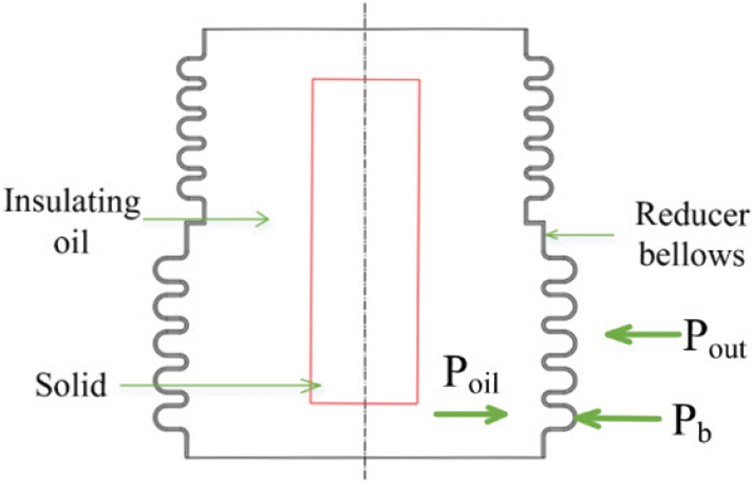
Figure 1: Schematic diagram of the reducer bellows
where Pout represents external pressure, Pb represents the force generated by deformation of the reducer bellows, and Poil represents internal insulating oil pressure.
When the reducer bellows is lowered with the instrument in the sea, Pout increases gradually. At the same time, internal pressure of the reducer bellows will be lower than external pressure. In order to balance internal and external pressure and achieve the purpose of pressure compensation, the reducer bellows will move down from location of the middle joint when pressure increases, that, the large-diameter bellow is compressed, and the small-diameter bellow is stretched. Since both ends are fixed, the total length in axial direction is unchanged. Nevertheless, the length of each bellow with either small-diameter and large-diameter varies differently (Fig. 2). Fig. 2a shows the initial state of the reducer bellows, and Fig. 2b shows the deformed state. Different colors indicate different degrees of change in each position. Therefore, internal insulating oil is squeezed, volume Vb of the reducer bellows becomes smaller and reduction amount is ΔVb, insulating oil volume Voil decreases, and Poil increases. In a word, when external pressure of the reducer bellows changes, the displacement of the reducer bellows with different diameters will change, resulting the volume of internal insulating oil changes, which in turn changes internal pressure, realizes balance of internal and external pressure, and achieves compensation of pressure. Among them, the change of pressure Poil of insulating oil is passive:
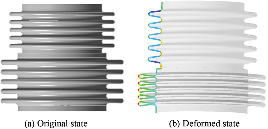
Figure 2: Structure diagram of the reducer bellows before and after deformation
(1) When Vb becomes smaller, Voil will become smaller and Poil will become bigger.
(2) When Vb becomes larger, Voil will become bigger and Poil will become smaller.
For Vb, when external pressure changes, reducer bellows will deform, then Vb will also change, and the change of volume ΔVb determines its performance of compensation. When pressure of the reducer bellows changes, its movement direction is primarily moving in the axial direction. The axial displacement determines the size of ΔVb, and the axial stiffness generally expresses the axial displacement of the reducer bellows. The smaller the axial stiffness is, the easier it is for the reducer bellows to move and deform in the axial direction, and the larger the change in axial displacement, the larger ΔVb, and the better performance of compensation. At the same time, the mechanical strength of the reducer bellows will also effect its axial change of displacement, which will affect performance of compensation. Under the same external pressure, the smaller the equivalent stress of the reducer bellows, the greater the mechanical-strength, the larger the allowable change of axial displacement, the larger ΔVb, and the better ability of pressure compensation. Therefore, the reducer bellows performance of pressure compensation was studied in following two aspects: axial stiffness and mechanical strength.
For insulating oil inside the reducer bellows, its volume change is a passive change, but the pressure and other forces generated by volume change will act on the reducer bellows in turn. Its volume change is affected by external pressure and temperature, and formulas are shown as follows [18]:
where ΔPoil represents the variable of internal insulating oil pressure, βoil represents the compression coefficient, ΔVp represents volume change of insulating oil concerning pressure, ay represents the expansion coefficient of insulating oil, aq represents air expansion coefficient, α represents gas content, ΔT represents the temperature difference, ΔVt is the volume change of insulating oil with the change of temperature, ΔVt represents the volume change of internal insulating oil with temperature changes.
Ignoring the effect of temperature, Pout increases, and Vb decreases. When Poil increases, the change of pressure is ΔPoil, and the insulating oil change of volume is ΔVp. When Vb and Voil decrease, the purpose of bellows pressure compensation is achieved. Considering the effect of temperature, provided that the external temperature is raised without the change of Pout, ΔT increases, ΔVt increases, Voil increases, and Vb increase, which decreases the deformation volume of the reducer bellows and increases the range of variation in volume. The ability of pressure compensation will increase due to the increase in temperature.
2.2 Analysis of Axial Stiffness of the Reducer Bellows
Through research on the compensation of pressure excitation of the reducer bellows, it is determined that the axial stiffness has a great influence on it, so it is necessary to discuss and analyze the axial stiffness of the reducer bellows. The empirical formula for calculating the axial elastic stiffness Ka of non-reducing bellows is:
where Ka represents the axial stiffness of the bellows, N/mm; Dm represents average diameter of the bellows, Dm = (Db+D)/2, mm; Etb represents elastic modulus of bellows at the selected temperature, Pa; tp represents nominal thickness of a layer of material of the forming bellows, mm; n represents number of layers of bellows; h represents the wave height, mm; Cf represents the correction factor for calculation of U-shaped bellows; N represents the wavenumber of bellows. The geometric structure of the reducer bellows is shown in Fig. 3.
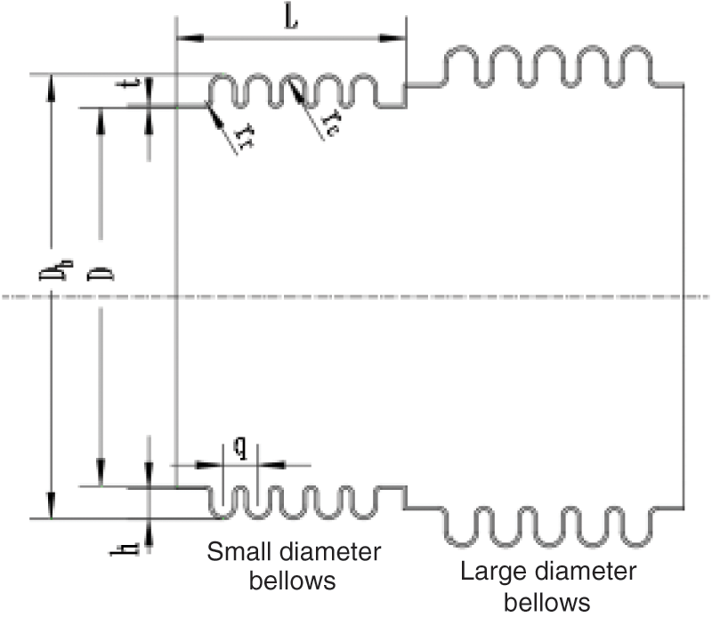
Figure 3: Schematic diagram of the geometric structure of the reducer bellows
For the designed reducer bellows, the empirical formula of bellows cannot be directly used for calculation. It is necessary to calculate the axial stiffness of the large-diameter bellow and the small-diameter bellow separately, and then use the equivalent stiffness principle to calculate the axial stiffness of the reducer bellows.
When the reducer bellows is fixed on one end face, a load is applied to the other end face; at this time both the large-diameter bellow and the small-diameter bellow are stretched, and the two bellows are both subjected to the same force. It can be determined that the combination of the reducer bellows is in series, and its equivalent stiffness is:
When the reducer bellows is in a fixed state at both ends, a pressure load is applied to its surface, the large-diameter bellow is compressed, the small-diameter bellow is stretched, and the displacement generated by the two bellows alone is the same. The combination mode of the reducer bellows is parallel, and its equivalent stiffness is:
3 Simulation Model Validation of the Reducer Bellows
For the reducer bellows, due to its innovative structure, it does not directly apply previous theories. It is necessary to use the combination of finite element simulation method, theoretical and experimental method to verify the simulation model correctness. On this basis, the sensitivity analysis of parameters affecting the pressure compensation is carried out, and the optimal parameter combination is determined. Firstly, perform a pressure analysis on the reducer bellows to determine the maximum pressure it can withstand. Furthermore, the bidirectional Fluid-Solid Interaction simulation is performed on the reducer bellows and the insulating oil inside. Then the deformation and maximum depth of the ocean determined under the change of external pressure and temperature. Now the specific structure of the reducer bellows can be obtained is simulated and analyzed.
3.1 Finite Element Model of the Reducer Bellows
The material of bellows is 304 stainless steel, its 06Cr19Ni10, the elastic modulus is 1.94 × 10¹¹ Pa, the Poisson’s ratio is 0.3, the density is 7930 kg/m3 . The bellows for experiments are mature products, which standard is GB/T 16749-2018 and the specifications are shown in Table 1.

3.1.2 Finite Element Model and Reducing Conditions
Finite element analysis of the axial stiffness of bellows is extensive. The research results show that it is feasible to use finite element method to study the axial stiffness of bellows. In this paper, finite element analysis software ANSYS Workbench is used to analyze the axial stiffness of bellows. Solidworks is used for 3D modeling of bellows, and then the model is imported to ANSYS Workbench for analysis. The simulation model uses a C3D8R mesh, which supports nonlinear parameters such as large deformation, stress strengthening and plasticity. The simulation model adopts the C3D8R grid, and Fig. 4 shows the finite element simulation model of the reducer bellows. The middle position of the large-diameter bellow and the small-diameter bellow is connected by welding. Now the end face of the small-diameter bellows is fixed, and a load is applied to the end surface of the large-diameter bellow to ensure the consistency of simulation boundary conditions in operating conditions.
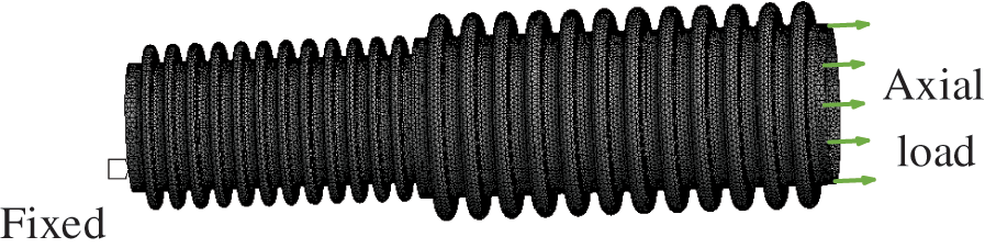
Figure 4: Reducer bellows finite element model
3.2 Axial Stiffness Verification of the Reducer Bellows
3.2.1 Theoretical Calculation of Axial Stiffness
The axial stiffness of the large-diameter bellow and the small-diameter bellow can be calculated by formula (4).
Large-diameter bellow: Kr1 = 368.69 N/mm;
Small-diameter bellow: Kr2 = 256.16 N/mm.
In the experiment, the fixed method of the reducer bellows is to fix one end face and apply a load to the other end face. It can be determined that the combination method is a series connection, and its equivalent axial stiffness is calculated by the formula (5).
Kr = 151.15 N/mm.
3.2.2 Experiment of the Reducer Bellows
Before the experiment, the large-diameter bellow and the small-diameter bellow are welded together. In order to reduce errors caused by welding, a set of comparative experiments are now performed. There are three samples in the experiment, that is to say number1, number2 and number3 (Fig. 5a). The experimental device used is a universal electronic material testing machine in the course of experiment. One end of the small-diameter bellow is fixed on the upper side of experimental device, and one end of the large-diameter bellow is fixed on the lower side of experimental device (Fig. 5b). The bellows were subjected to tensile experiments. The stress-strain curves of the reducer bellows measured after the experiment are shown in Fig. 6.

Figure 5: Experimental diagram of the reducer bellows
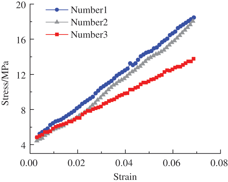
Figure 6: Stress-strain curve of the reducer bellows
The axial stiffness of the reducer bellows can be obtained through linear regression equation:
Number 1: Kp1 = 147.05 N/mm;
Number 2: Kp2 = 146.34 N/mm;
Number 3: Kp3 = 136.13 N/mm.
The average axial stiffness of the reducer bellows is:
Kp = (Kp1 + Kp2 + Kp3)/3 = 143.17 N/mm.
3.2.3 Simulation Calculation of Axial Stiffness
(1) Mesh sensitivity analysis
The reducer bellows is analyzed statically and large deformation is opened. The 8-node hexahedral element is used in the reducer bellows, and its mesh size independence is verified. The linear force is applied to the reducer bellows in the elastic deformation range and the displacement of the reducer bellows in different mesh sizes is observed. Now set the order of the reducer bellows mesh size is 0.3, 0.35 and 0.4 mm, 0.45 and 0.5 mm, the grid number is 168590, 102568, 76041, 66633, 52699. Table 2 shows the specific data of displacement changes of the reducer bellows when they are subjected to force under different mesh sizes, and its trend can be visually seen in Fig. 7. It can be seen from the Fig. 7 that the reducer bellows changes of displacement is close to each other under different mesh sizes, satisfying verification of grid independence. Increasing the number of grids will increase the calculation time of simulation, so in the subsequent simulation, the mesh size can be set at 0.5 mm.

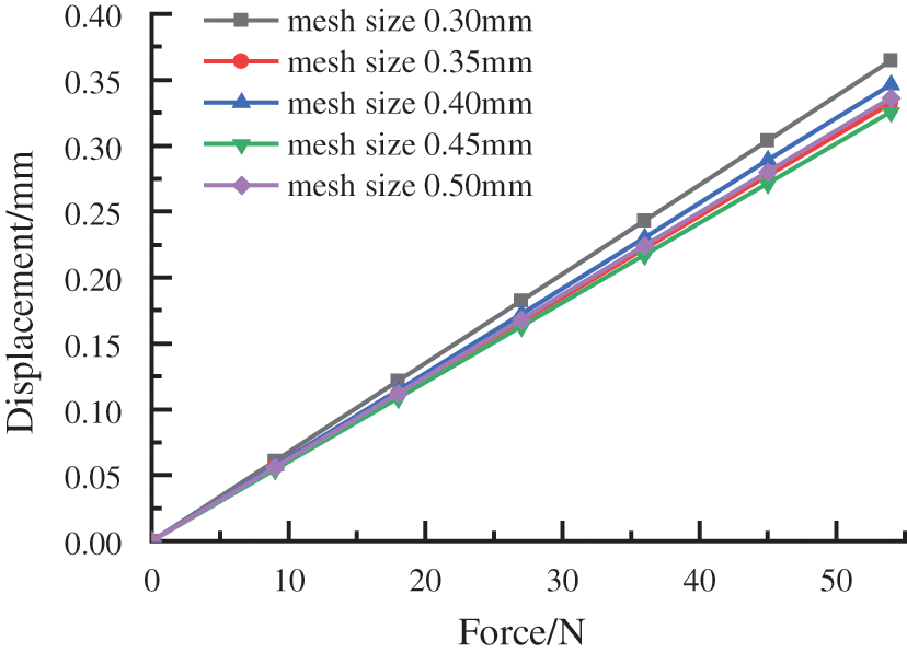
Figure 7: Mesh sensitivity analysis
(2) Simulation calculation
The model with mesh size of 0.5 mm is selected for the simulation calculation, and the axial stiffness of the reducer bellows only needs to be calculated in linear range, which can be obtained by Hooke’s law:
where Fa represents the axial force, Ka represents the axial stiffness in the linear phase and x represents the axial displacement. During the simulation, the initial axial load was selected as 9 N, in order to correspond to formula (7), and to make the relationship between stiffness, force and deformation easier to understand, we chose multiple relationships to apply force, and obtained the axial displacement of the reducer bellows through simulation. The axial stiffness under multiple relational forces can be obtained by formula (7), as shown in Table 3. Due to the simulation error, the axial stiffness is slightly different, so it is necessary to solve the axial stiffness of the reducer bellows by a linear regression equation:
Ka = 160.61 N/mm.

Through theoretical calculation, experiment and simulation, the axial stiffness of the reducer bellows obtained is: 151.15, 143.17, and 160.61 N/mm, respectively. The error between simulation and theoretical calculation is 6.3%, and the error between simulation and experiment is 10.9%. The error between theoretical calculation and simulation is small, which shows that the calculation method of equivalent stiffness can be used to calculate the axial stiffness of the reducer bellows. The error between experiment and simulation is large, which may be due to the following reasons: the wall thickness of the selected bellows is relatively thin, the shell is perforated during welding, which cannot achieve the ideal welding quality, and is different from the simulation model; The axial stiffness of different corrugated pipes cannot be guaranteed, resulting in a discrepancy with the real situation when calculating the displacement at the end. Through experiments and theoretical calculations, the final comparison shows that the error obtained by the simulation method is within the acceptable range, which verifies the reliability and authenticity of the simulation analysis.
4 Sensitivity Study of the Reducer Bellows Parameters Performance of Compensation
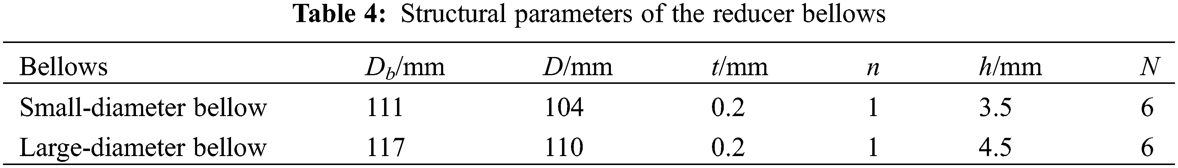
In order to obtain the reducer bellows performance of compensation, it is necessary to carry out a sensitivity analysis on the parameters affecting the performance of compensation, such as wall thickness, wave number, and wave height. In this experiment, an undersea test instrument was selected as the research object, and the structural size of the reducer bellows was initially determined (Table 4). Now, the Transient Structure module of ANSYS Workbench software is used to optimize and simulate the structural parameters, which can obtain the specific changes of the structure with time when the reducer bellows is under external load. The simulation model uses C3D8R mesh, and the large deformation state needs to be turned on during setting. The two ends of the bellows are fixed, and the uniform load is applied on the external surface. The external load applied to the reducer bellows Pb is 0–0.2 MPa.
4.1 Effect of Wall Thickness on Performance of Pressure Compensation
The wall thickness of the reducer bellows has a significant impact on its axial stiffness and mechanical strength, and it has an enormous impact on the ability to resist and compensate for pressure in the deep ocean. Now analyze the variation law of the displacement and equivalent stress of the reducer bellows with the external pressure Pb when the wall thickness is 0.2, 0.25, 0.3, 0.35 and 0.4 mm.
It can be seen from Fig. 8 that with the increase of external pressure, the displacement of the reducer bellows also increases. As the wall thickness increases, the slope of the displacement change decreases. As the wall thickness increases, the slope of the displacement change decreases. It can be concluded that increasing the wall thickness will increase the axial stiffness of the reducer bellows, reduce its ability to compensation and increase the ocean depth allowed to use. It can be seen from Fig. 9 that with the increase of external pressure, the stress of the reducer bellows will increase, and the thicker the wall thickness, the smaller the slope of the stress change. Increasing the wall thickness can improve the resistance of the reducer bellows to pressure and increase the maximum depth of the ocean. But when the wall thickness increases from 0.35 to 0.4 mm, the slope of stress reduction tends to be gentle. At the same time, consider the ability to compensate for pressure and resist pressure, when the wall thickness is 0.3 mm, the reducer bellows can have a large change on displacement, a small axial stiffness, and a greater ability to withstand pressure and mechanical strength. Under the same external conditions, it can obtain large compensation in volume.
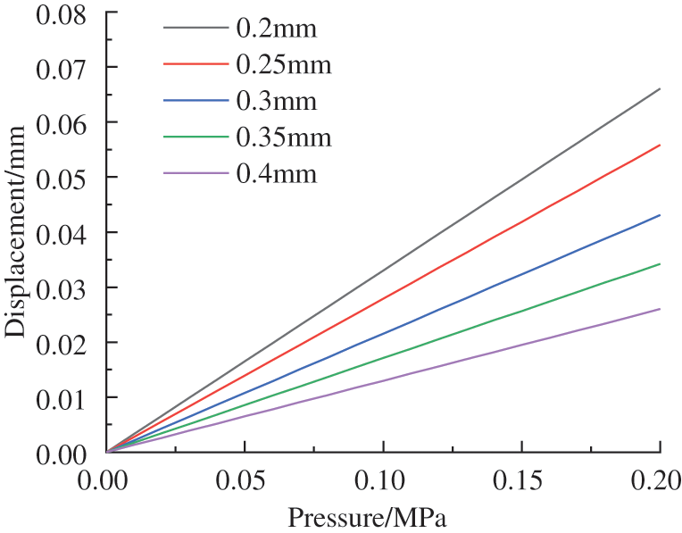
Figure 8: Variation of displacement with different wall thickness
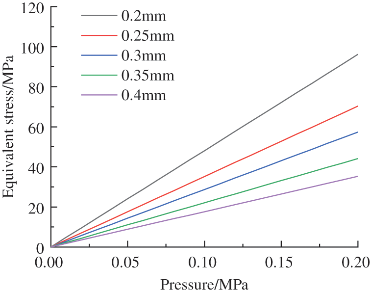
Figure 9: Variation of equivalent stress with different wall thicknesses
4.2 Effect of Wavenumber on Performance of Pressure Compensation
The wavenumber combination of the reducer bellows has an influence on its axial stiffness and mechanical strength, and the influence on the capacity of the compensation cannot be ignored, so it is necessary to select a right combination. Now change the wavenumber combination mode of the small diameter-bellow and the large-diameter bellow, and analyze the variation law of the displacement and the equivalent stress of the reducer bellows with the external pressure. When the total wavenumber is 12, the displacement and equivalent stress of the reducer bellows with a wavenumber ratio of 4:8, 5:7, 6:6, 7:5 and 8:4 are analyzed.
It can be seen from Fig. 10 that the displacement of the reducer bellows increases with the increase of external pressure. When the wavenumber ratio is 7:5 or 5:7, the slope of displacement change is the largest. When the wavenumber ratio is 8:4 or 4:8, the slope of displacement change becomes smaller, and the slope of displacement change is the minimum at 6:6. Therefore, when the total wavenumber is unchanged, appropriately increasing the wavenumber of large diameter bellow or small diameter bellow can increase the slope of displacement variation, reduce the minimum axial stiffness, and improve the performance of compensation. It can be seen from Fig. 11 that with the increase of external pressure, the stress of the reducer bellows will also increase, and the slope of stress change increases with the increase of wavenumber ratio. When the wavenumber ratio is 4:8, due to the small wave number of the small-diameter bellow, the overall structure of the reducer bellows will reach plastic deformation in advance during the deformation process, consequently the subsequent equivalent stress contour will not show a straight state. At the same time, considering the capacity of compensation and the capacity of bearing pressure, when the wavenumber ratio of the reducer bellows is selected within 6:6 to 8:4, it has a high-pressure performance of compensation, which can increase the bellows depth of the ocean.
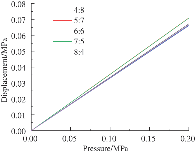
Figure 10: Variation of displacement with different wave number ratios

Figure 11: Variation of equivalent stress with different wavenumber ratios
4.3 Effect of Intermediate Distance on Performance of Pressure Compensation
In the reducer bellows structure, the intermediate distance between the small diameter bellow and the large diameter bellow significantly impacts its axial stiffness and mechanical strength. Therefore, it is necessary to determine a suitable distance of intermediate to improve the reducer bellows ability of compensation. Now change the middle distance of the reducer bellows, and analyze the changing law of the displacement and equivalent stress of the reducer bellows with the external pressure when the middle distance of the reducer bellows is 0, 1, 2, 3, 4 mm.
It can be observed from Fig. 12 that with the increase of external pressure, the displacement of the reducer bellows will increase. When the middle distance of the reducer bellows is in the range of 2 to 4 mm, the slope of the displacement change is relatively nearby, indicating that the displacement change of the reducer bellows within this range is larger, the axial stiffness is smaller, and the specific performance of pressure compensation is higher. It can be seen from Fig. 13 that with the increase of external pressure, the stress of the reducer bellows will increase. When the middle distance is from 0 to 2 mm, the slope of the change in pressure will decrease with the increase of the middle distance; when the middle distance is greater than 2 mm, the slope of the change in pressure will increase with the increase of the middle distance; when the middle distance is 2 mm, the slope of the change in pressure is the smallest. At this time, the reducer bellows capacity of bearing pressure is the highest and the mechanical strength is high. Therefore, considering the capacity of compensation and the capacity of bearing pressure, when the distance of intermediate is 2 mm, the axial stiffness is small, and the mechanical strength is high, it can provide a large compensation of volume, and the capacity of pressure compensation is the highest. The larger the distance of intermediate is, the greater the slope of the displacement change will be.
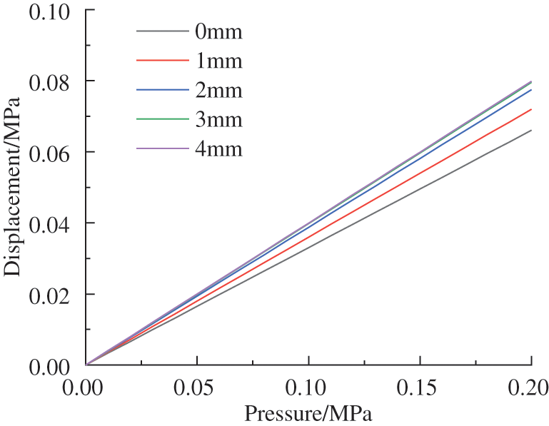
Figure 12: Variation of displacement with different intermediate distance
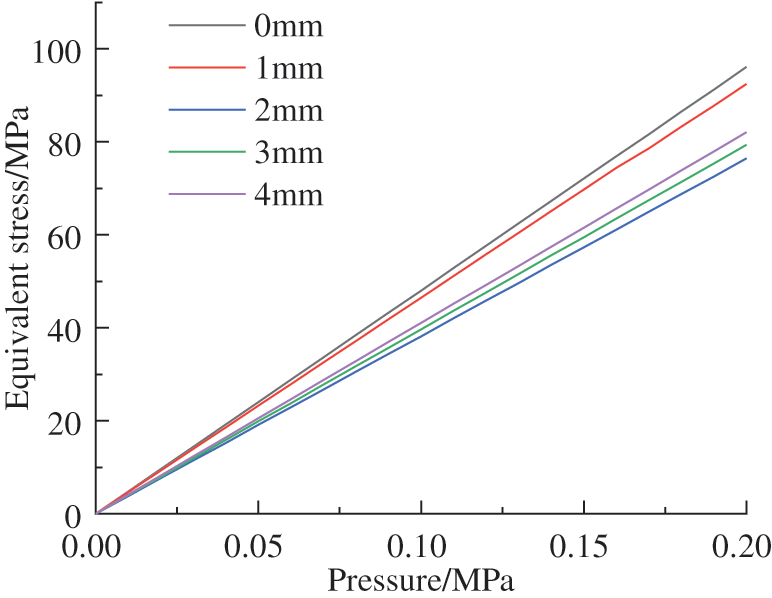
Figure 13: Variation of equivalent stress with different intermediate distance
4.4 Effect of Wave Height on Performance of Pressure Compensation
The change of the wave height and the combination of the wave height of the reducer bellows will affect its axial stiffness and mechanical strength, and affect its ability of pressure compensation, so it needs to be discussed and analyzed. Two groups of analyses will be performed: one group changes the wave height of the small-diameter bellow and the large-diameter bellow at the same time, and the other group changes the wave height of the large-diameter bellow alone, and analyzes the variation law of the reducer bellows performance of pressure compensation under different wave heights.
4.4.1 Wave Height Variation of Small Diameter Bellows and Large Diameter Bellows
Change the wave height of the small diameter bellow and the large diameter bellow at the same time, analyze the variation law of displacement and equivalent stress of the reducer bellows with external pressure when the wave height is 3.5–4.5 mm, 4–5 mm, 4.5–5.5 mm, 5–6 mm and 5.5–6.5 mm.
It can be seen from Fig. 14 that with the increase of external pressure, the displacement of the reducer bellows will increase, and the slope of the displacement change will increase with the change of the wave height. The increase in the height of the bellows will make the bellows have a small axial stiffness, and at the same time have a higher capacity of pressure compensation. It can be seen from Fig. 15 that with the increase of external pressure, the stress of the reducer bellows will increase, and the slope of the stress change will increase due to the larger wave height. The increase in the wave height will reduce the reducer bellows capacity of bearing pressure and mechanical strength. For the reducer bellows used in the deep-sea field, the capacity of compensation and the capacity of bearing pressure are considered simultaneously, and the wave height range is selected from 4–5 mm to 5–6 mm. At this time, the axial stiffness of the reducer bellows is small, the mechanical strength is high, the deformation of volume is large, and the capacity of bearing pressure and the capacity of compensation are maintained at a high level.
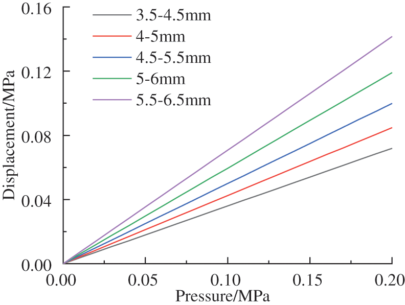
Figure 14: Variation of displacement with different wave heights
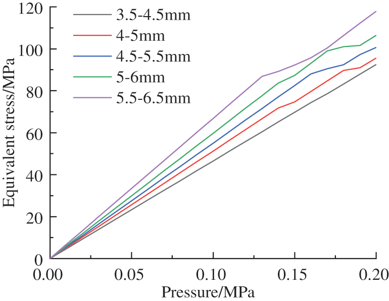
Figure 15: Variation of equivalent stress with different wave heights
4.4.2 Wave Height Variation of Large Diameter Bellows
Now we keep the wave height of the small-diameter bellow at 3.5 mm, analyze the variation law of the displacement and equivalent stress of the reducer bellows with external pressure when the wave height of the large-diameter bellow at 4.5, 5, 5.5, 6 and 6.5 mm.
It can be seen from Fig. 16 that with the increase of external pressure, the displacement of the reducer bellows will increase, and the slope of the displacement change increases with the increase of the lower wave height. Therefore, increasing the lower wave height will cause the axial stiffness of the reducer bellows to decrease, and the larger the deformation of volume, the higher the performance of pressure compensation. Comparing Figs. 16 and 17, it can be concluded that the maximum change of displacement is 0.105 mm when the wave height changed alone. When the wave height is changed at the same time, the maximum change of displacement is 0.141 mm. It can be seen that the influence of the lower wave height on the axial stiffness is smaller than that of the upper wave height. Therefore, the upper wave height should be considered first when increasing the wave height.

Figure 16: Displacement variation of wave height of different large diameter bellows

Figure 17: Equivalent stress variation of wave height of different large diameter bellows
It can be seen from Fig. 17 that with the increase of external pressure, the stress of the reducer bellows will increase, the slope of stress change will increase with the increase of the lower wave height, and the mechanical strength will decrease with the increase of the lower wave height. Comparing Figs. 15 and 17, it can be seen that there is little difference in the reducer bellows change of stress, and the mechanical strength of the large-diameter bellow alone and the wave height of the reducer bellows are similar. Therefore, in order to obtain larger deformation of displacement and smaller equivalent stress, the wave height of the small-diameter bellow should be firstly considered when designing the wave height of the reducer bellows, because the influence of the wave height of the small-diameter bellow on the displacement and equivalent stress of the reducer bellows is greater than that of the large-diameter bellows. Appropriately increasing the wave height of small-diameter bellow and decreasing the wave height of large-diameter bellow can greatly improve the reducer bellows mechanical strength and ability of pressure compensation, and increase the ability of volume deformation.
Through the sensitivity analysis of the parameters of the reducer bellows, the preferred parameters of the reducer bellows is: the wall thickness is 0.3 mm, the wavenumber ratio is 7:5, the intermediate distance is 2 mm, the inner diameter of the small bellow is 104 mm, the wave height is 5 mm; the inner diameter of the large bellow is 111 mm, the wave height is 5 mm. The inside of the reducer bellows is insulating liquid; the density of the insulating liquid is 920 kg/m3, the bulk modulus is 6 × 10⁸ Pa, and the thermal expansion coefficient is 0.0008. The density of seawater is 1020 kg/m3. The reducer bellows initial volume of internal is Vb = 671180 mm3, the volume of insulating oil is Voil = 442986 mm3, the volume of solid is Vs = 228194 mm3, and the initial temperature is set to 25°C. The boundary conditions are: fix both ends of the bellows and apply pressure of 0.89 MPa to the outer surface.
When the external pressure Pb is 0.89 MPa, the axial motion position of the large-diameter bellow reaches the limit, and the reducer bellows capacity of compensation reaches the maximum at this time. The maximum displacement is the middle position of the deformed bellows, and the maximum value is 1.1504 mm (Fig. 18). The maximum equivalent stress is the trough position of the small-diameter bellow, and the maximum value is 178.01 MPa (Fig. 19). After being subjected to external pressure, the internal volume of the reducer bellows is 625569 mm3, and the volume reduction is 45611 mm3. From the compressibility formula (2) of the liquid, ΔP can be calculated; by substituting Pb and Poil into formula (1), we can be obtained that Pout = 62.6 MPa and the maximum allowable ocean depth is 6284 m, which means that the maximum allowable ambient pressure without failure of the reducer bellows under this environmental condition.
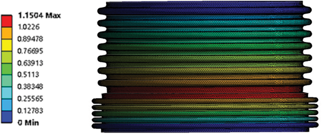
Figure 18: Axial displacement cloud map after deformation
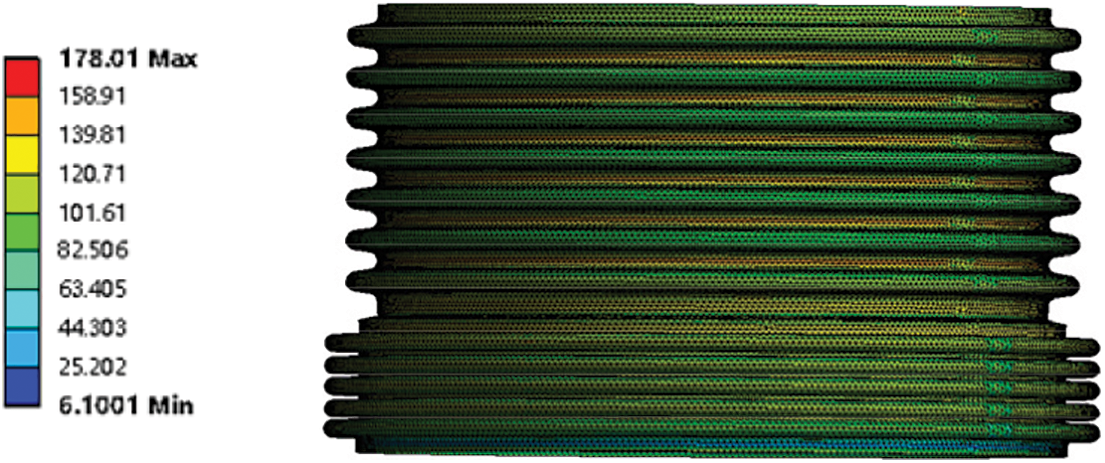
Figure 19: Equivalent force cloud after deformation
The model is simulated and verified by two-way Fluid-solid Interaction (Fig. 20). The optimized reducer bellows parameters are selected as the simulation size. The internal insulating oil parameters are set as shown above, and the insulating oil is set as a compressible and non-Newtonian fluid. Considering that the convergence of the simulation calculation is difficult to meet, the condition of applied boundary is that the external pressure is increased to 60 MPa, and the volume change of the insulating oil is observed after the external pressure is applied. The simulation results show that when external pressure increases to 60 MPa, the volume of insulating oil becomes 399404 mm3 (Fig. 21), and the reduction of volume is 43582 mm3. According to formulas (1), (2), the pressure of the reducer bellows is 0.97 MPa. At this time, the external pressure of the reducer bellows slightly exceeds its limit, and the error may be due to the time step being set too fast, resulting in the deformation not being transmitted in time, but the error is within an acceptable range.
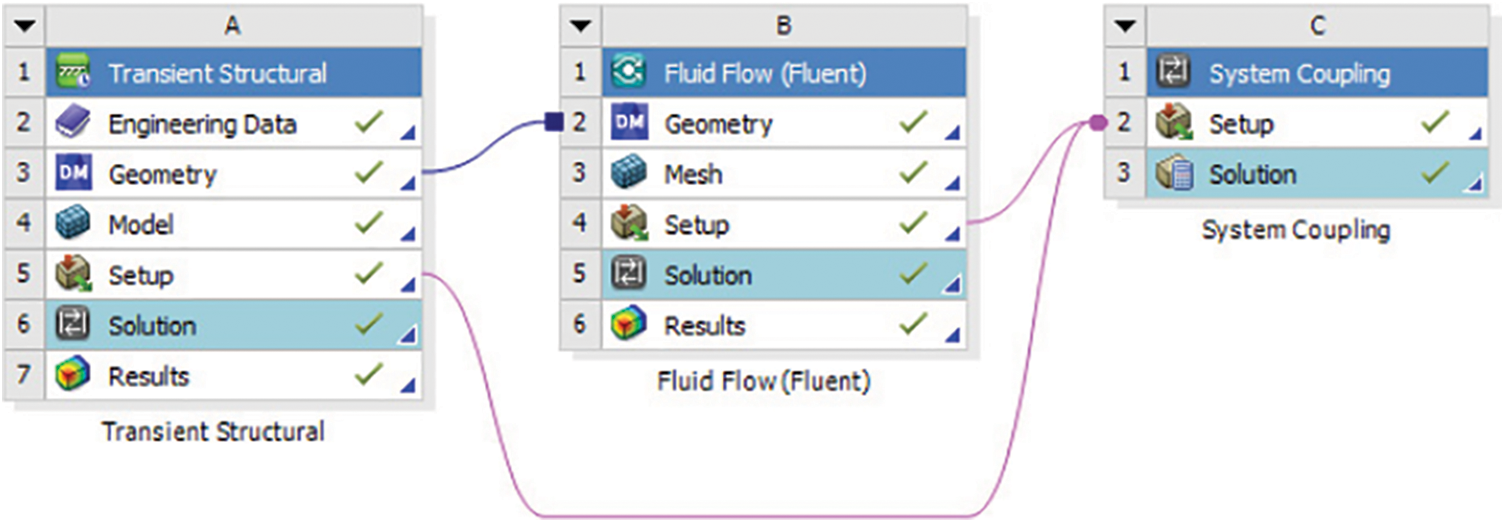
Figure 20: Two-way fluid-structure interaction operation settings
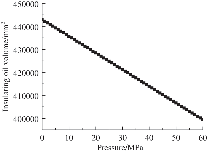
Figure 21: The volume of insulating oil varies with pressure
Considering the principle of compressibility of liquids, the following measures can be taken to improve the reducer bellows performance of pressure compensation: reduce the initial volume Voil of the internal insulating oil; choose insulating oil with a larger bulk modulus K; optimize the design of the structural parameters of the reducer bellows. All the above measures can increase the reducer bellows maximum pressure of external and increase its maximum depth of working. This provides a basis for the subsequent design and research of the reducer bellows.
The following conclusions can be drawn from the study:
(1) It is determined that the axial stiffness and mechanical strength are the main factors affecting the reducer bellows compensation of pressure.
(2) Sensitivity analysis of the reducer bellows parameters to clarify the influence of wall thickness, wave number ratio, intermediate distance and wave height on performance of pressure compensation.
(3) A certain type of bellows used in testing instruments of the deep ocean is analyzed, and the following conclusions are drawn: the capacity of compensation is best when the wavenumber ratio is between 6:6 and 8:4, the wall thickness is 0.3 mm, and the wave height is between 4–5 mm and 5–6 mm. The reducer bellows can be used in the deep sea with a pressure of 62.6 MPa and a working water depth up to 6284 m after optimization in the example analysis. Moreover, it will improve the resistance of bellows to external pressure when increasing the axial stiffness Kc, the volume of inner Vb and the bulk elastic modulus of the internal insulating oil Koil, or lowing the insulating oil volume Voil.
(4) The research results not only have pertinence and significance for the design and optimization components of pressure balance used in deep-sea instruments, but also provide reference value for other structures such as a large high-pressure deformation and fluid thermal deformation of volume.
Funding Statement: Key Laboratory of Petroleum and Natural Gas Equipment of Ministry of Education.
Conflicts of Interest: The authors declare that they have no conflicts of interest to report regarding the present study.
References
1. Lei, Y., Wei, H., Guo, H., Guo, J. (2020). Study on pressure compensation of underwater transformers based on bellows. Ship Power Technology, 40(9), 54–57. https://doi.org/10.13632/j.meee.2020.09.014 [Google Scholar] [CrossRef]
2. Xiao, S., He, X. Y., Zhang, J. K., Zhou, S. C., Liu, S. H. et al. (2021). A pressure-balanced centering electric drill pipe. Sichuan Province, CN113250625A. https://kns.cnki.net/kcms/detail/detail.aspx?dbcode=SCPD&dbname=SCPD202203&filename=CN113250625B&uniplatform=NZKPT&v=xrj4uaJzZZyGKZ_rXlnIVDRog3hhJjz4b0tHAlm74w9NHTuFhMtelOLQ1-fgIyYe [Google Scholar]
3. Sun, E., Wang, T., Zhu, S. (2020). An experimental study of bellows-type fluidic soft bending actuators under external water pressure. Smart Materials and Structures, 87005. https://doi.org/10.1088/1361-665X/ab9518 [Google Scholar] [CrossRef]
4. Huo, S. H., Yan, W. Z., Xu, X. J., Yuan, Z. (2021). Bending characteristics of the reinforced S-shaped bellows under internal pressure. International Journal of Pressure Vessels and Piping, 192(5), 104412. https://doi.org/10.1016/j.ijpvp.2021.104412 [Google Scholar] [CrossRef]
5. Zinovieva, T. V., Smirnov, K. K., Belyaev, A. K. (2019). Stability of corrugated expansion bellows: Shell and rod models. Acta Mechanica, 230(11), 4125–4135. https://doi.org/10.1007/s00707-019-02497-6 [Google Scholar] [CrossRef]
6. Zinovieva, T. V., Piskunov, V. A. (2021). Compensatory bellows oscillations as a corrugated shell with liquid inside. PNRPU Mechanics Bulletin, 1, 31–40. https://doi.org/10.15593/perm.mech/2021.1.04 [Google Scholar] [CrossRef]
7. Aistov, A. I., Skvortsov, Y. V., Chernyakin, S. A., Perov, S. N. (2017). Fatigue life prediction for expansion bellows. AIP Conference Proceedings, 1798(1). https://doi.org/10.1063/1.4972594 [Google Scholar] [CrossRef]
8. Reich, J. E. A., Cardella, A., Capriccioli, A., Koppe, T., Missal, B. et al. (2007). Experimental verification of the axial and lateral stiffness of large W7-X rectangular bellows. Fusion engineering and design, 82(15–24), 1924–1928. https://doi.org/10.1016/j.fusengdes.2007.04.033 [Google Scholar] [CrossRef]
9. Radhakrishna, M., Rao, C. K. (2004). Axial vibrations of U-shaped bellows with elastically restrained end conditions. Thin-Walled Structures, 42(3), 415–426. https://doi.org/10.1016/S0263-8231(03)00130-7 [Google Scholar] [CrossRef]
10. Huang, X. C., Zhang, Z. G., Sun, J. Y., Zhang, Z. Y., Hua, H. X. et al. (2017). Analytical stiffness model of a fluid-filled U-shaped bellows based three-parameter fluid damper for micro-vibration suppression. Aerospace Science and Technology, 69(3), 357–369. https://doi.org/10.1016/j.ast.2017.07.004 [Google Scholar] [CrossRef]
11. Pratama, E. Y. (2017). Investigation of failed LNG boil off gas transfer line expansion bellows using finite element analysis approach. SPE/IATMI Asia Pacific Oil & Gas Conference and ExhibitionIndonesia. https://doi.org/10.2118/186394-MS [Google Scholar] [CrossRef]
12. Li, X., Bi, T., Xu, H. W., Shen, X. J. (2022). Study on influencing factors of temperature variation displacement compensation behavior of gas insulated switchgear shell bellows. Energies, 15(11), 3954. https://doi.org/10.3390/en15113954 [Google Scholar] [CrossRef]
13. Pagar, N. D., Gawande, S. H. (2019). Experimental investigations on meridional and circumferential stresses of bellows due to internal pressure. ASME 2019 Gas Turbine India Conference. https://doi.org/10.1115/GTINDIA2019-2771 [Google Scholar] [CrossRef]
14. Belyaev, A. K., Zinovieva, T. V., Smirnov, K. K. (2017). Theoretical and experimental studies of the stress-strain state of expansion bellows as elastic shells. Petersburg Polytechnical University Journal: Physics and Mathematics, 3(1), 7–14. https://doi.org/10.1016/j.spjpm.2017.03.003 [Google Scholar] [CrossRef]
15. Subramanian, C., Roy, H., Kumar, A., Mondal, A., Ray, S. et al. (2021). Failure cause analysis of an expansion bellow of integrated turbine unit. International Journal of Pressure Vessels and Piping, 191(3), 104360. https://doi.org/10.1016/j.ijpvp.2021.104360 [Google Scholar] [CrossRef]
16. Karagiozis, K. N., Païdoussis, M. P., Amabili, M. B., Misra, A. K. (2008). Nonlinear stability of cylindrical shells subjected to axial flow: Theory and experiments. Journal of Sound and Vibration, 309(3–5), 637–676. https://doi.org/10.1016/j.jsv.2007.07.061 [Google Scholar] [CrossRef]
17. Liu, J., Liu, Y., Li, L., Liu, J. (2021). Numerical investigation of the effect of material properties on forming metal bellows. The International Journal of Advanced Manufacturing Technology, 116(7–8), 2425–2436. https://doi.org/10.1007/s00170-021-07551-z [Google Scholar] [CrossRef]
18. Lv, Y., Liang, L. R., Li, Y. W., Chen, Y., Chouw, N. (2021). Experimental and finite-element study of buried pipes connected by bellow joint under axial cyclic loading. Journal of Pipeline Systems Engineering and Practice, 12(1), 04020069. https://doi.org/10.1061/(ASCE)PS.1949-1204.0000524 [Google Scholar] [CrossRef]
19. Shen, G. J., Li, M., Xue, X. (2020). Analysis and experimental study of fluid-solid coupling dynamic characteristics of metal bellows. Ordnance Materials Science and Engineering, 43(5), 36–42. https://kns.cnki.net/kcms/detail/detail.aspx?dbcode=CJFD&dbname=CJFDLAST2020&filename=BCKG202005011&uniplatform=NZKPT&v=xFoW8P1x5OgtGJao0Mo5mkoEPVXVQKnSjo5ZOjoth2lEhlWVlOBe4cgTJI8VB9He [Google Scholar]
Cite This Article
 Copyright © 2023 The Author(s). Published by Tech Science Press.
This work is licensed under a Creative Commons Attribution 4.0 International License , which permits unrestricted use, distribution, and reproduction in any medium, provided the original work is properly cited.
 Downloads
 Citation Tools