
 Submit a Paper
 Propose a Special lssue
 Open Access
ARTICLE

Optimization of a Diesel Injector Nozzle
1
School of Energy and Power Engineering, Shandong University, Jinan, 250061, China
2
Longkou Longbeng Diesel Injection High Technology Equipment Co., Ltd., Longkou, 265018, China
* Corresponding Authors: Ke Sun. Email: ; Guihua Wang. Email:
(This article belongs to the Special Issue: Recent Advances in Fluid Mechanics and Thermal Sciences II)
Fluid Dynamics & Materials Processing 2023, 19(11), 2933-2951. https://doi.org/10.32604/fdmp.2023.028804
Received 08 January 2023; Accepted 14 March 2023; Issue published 18 September 2023
 View Full Text
 Download PDF
Abstract
Multiphase simulations based on the VOF (Volume of Fluid) approach, used in synergy with the cavitation Schnerr-Sauer method and the K-Epsilon turbulence model, have been conducted to study the behavior of an injector nozzle as a function of relevant structural parameters (such as the spray hole diameter and length). The related performances have been optimized in the framework of orthogonal experimental design and range analysis methods. As made evident by the results, as the spray hole diameter increases from 0.10 to 0.20 mm, the outlet mass flow rate grows by 243.23%. A small diameter of the spray hole, however, has a beneficial effect in terms of cavitation suppression. Moreover, rounding the spray hole can effectively increase the outlet mass flow rate and improve the flow characteristics while mitigating the cavitation phenomenon inside the spray hole. In particular, with the optimized nozzle design, the outlet mass flow rate can be increased by 13.33%, while the fuel vapor volume is reduced by 33.53%, thereby, leading to significant improvements in terms of flow characteristics and cavitation control.Keywords
Nomenclature
| | Volume fraction of gas phase |
| | Volume of the gas phase |
| | Volume of the calculation cell |
| | Density of the mixture material in the calculation cell |
| | Velocity of the flow |
| D | Diameter of spray hole |
| L | Length of spray hole |
| r | Radius of the inlet fillet of the spray hole |
| A | Angle between the centerline of the spray hole and the vertical axis of the nozzle |
| H | Maximum lift of the needle |
Since the advent of diesel engine high pressure common rail fuel system, for obtaining better fuel atomization effect, the pressure of injection has been increasing, and the maximum injection pressure of the common-rail system using the piezoelectric amplifier has reached 270 MPa, while the diameter of the nozzle spray hole continues to shrink, which leads to a further increase in jet velocity as well. At present, some scholars have found that raising the injection pressure can effectively reduce the emission of particulate matter, but when the pressure is raised to a certain level, further raising the injection pressure has little effect on the Sauter mean diameter (SMD) of fuel atomization. It is therefore important that relevant research and analysis be performed on the optimization of the structural parameters of the nozzle [1].
An injector is the bridge connecting the high-pressure line and the diesel engine combustion chamber, and the main components of the injector are the solenoid valve, control valve, piston and needle valve coupling, etc. High-pressure fuel is delivered by the common rail pipe; there are 2 fuel delivery routes within the injector, one leading into the control chamber above the control piston, and the other leading into the pressure chamber at the top of the needle valve. When the solenoid valve receives a control signal and turns on, the control chamber outlet hole gradually opens. At this time, the flow of fuel between inlet and outlet gradually decreases, the pressure acting on the piston weakens, the needle valve gradually rises, and fuel flows into the nozzle pressure chamber and is sprayed out through the spray hole, forming a fuel spray.
When fuel flows from the pressure chamber into the spray hole, there is a sudden reduction on the flow cross-section, which forms a local recirculation area, because of the existence of recirculation areas, the reduction of the flow area within the spray hole happen, this phenomenon is called vena constriction. Fig. 1 shows the constriction phenomenon. When the fuel flows into the spray hole, the flow area is rapidly reduced, and the velocity of the flow is further accelerated. According to Bernoulli’s equation, at this time the static pressure of flow is significantly lower than in the pressure chamber, forming a very small negative pressure area at the entrance. As the fuel static pressure reaches its saturation pressure, its internal core of gas gradually grows larger, many bubbles gather to produce a larger cavitation, and the volume fraction of gas in this area increases sharply. This phenomenon is called cavitation [2]. This phenomenon is different from boiling phase transition [3]. Fig. 2 shows the cavitation phenomenon. The existence of cavitation will affect the reliability and economy of the injector work process [4]; cavitation will corrode the wall of the spray hole [5], and when the bubbles rupture the inner wall of the spray hole will be impacted, shortening the service life of the spray hole [6]. Moreover, the appearance of cavitation results in a reduction of the effective area of flow in the hole [7], reducing the flow coefficient at the spray hole, and which reflected in the outlet will not only lead to a decreased mass flow rate, but also cause uneven fuel injection thereby affecting the uniformity of the work of each cylinder [8].
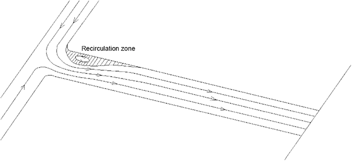
Figure 1: The constriction phenomenon inside the spray hole
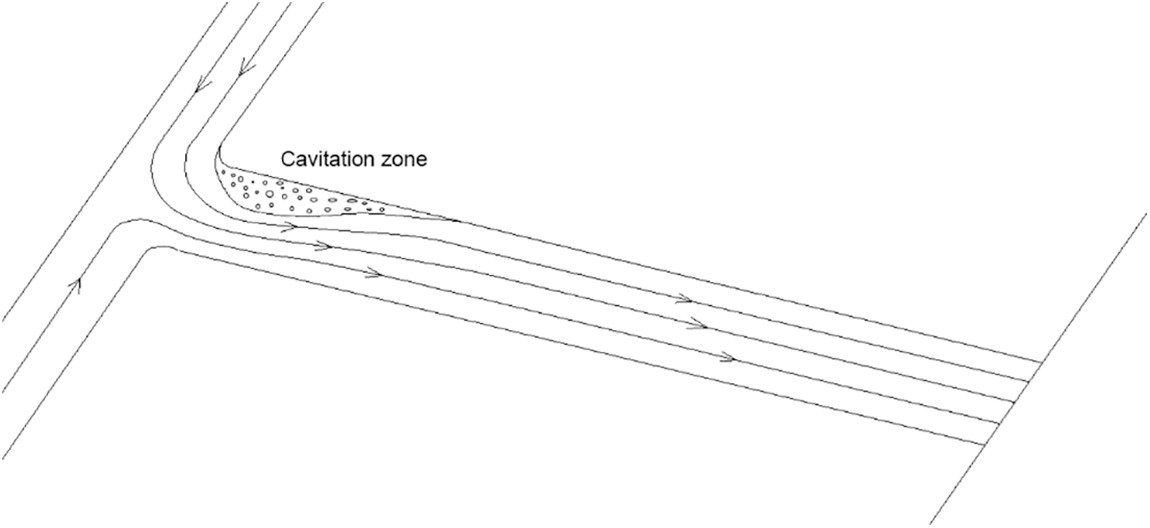
Figure 2: The cavitation phenomenon inside the spray hole
In the analysis of the flow characteristics, due to its small size being limited by the processing method, the test is generally performed on the geometric enlargement of the nozzle size [9] by scaling up according to the principle of geometric similarity and processing to obtain a larger visualization of the nozzle model, to emulate the flow characteristics in the actual nozzle [10]. Most of the existing experimental studies have been validated using scaled-up transparent nozzles; Mamaikin et al. [11] conducted an experimental study of cavitation flow on a real-size GDI nozzle made of acrylic using a high-power laser-based high-speed digital imaging technique and showed that a higher ambient back pressure reduced the generation of internal cavitation in the nozzle. However, it has also been pointed out that the cavitation phenomenon in the scaled-up nozzle and the real nozzle is not exactly the same. To overcome the existing challenges of small nozzle size and inconvenient test, most of the studies used numerical simulation and simulation calculation methods to explore the flow characteristics of nozzles [12]. Wang [13], using HYDSIM software, conducted a one-dimensional simulation analysis of the common rail system to study the influence of the injection characteristics by each structural parameter of the nozzle. However, the information obtained from the one-dimensional simulation is very limited and cannot observe the internal flow field and flow characteristics of the nozzle. Deng et al. [14] investigated the effect of spiral flower orifice structural parameters on the cavitation. Flow, and primary atomization characteristics of diesel engine nozzles using the multiphase flow coupled large eddy simulation (VOF-LES) method [15], the results showed that the jet ejected from the spiral flower nozzle has a larger diffusion angle and smaller droplet size. Liu et al. [16] used MATLAB/Simulink software to conduct a one-dimensional simulation of the nozzle and studied the effect of structural parameters such as inlet and outlet hole diameter and bypass hole diameter on the fuel injection characteristics.
In summary, several scholars have studied the effect of nozzle structure on injection characteristics using one-dimensional simulation, but the distribution of cavitation within the spray hole cannot be observed by one-dimensional simulation alone. Therefore, in this study, the Schnerr-Sauer cavitation model is used to analyze the flow characteristics of a diesel nozzle spray hole. The cavitation distribution and pressure are obtained by the model, the outlet mass flow rate and fuel vapor volume were selected as optimization targets to optimize the structure through orthogonal testing and range analysis. To achieve higher outlet flow rate and smaller fuel vapor volume fraction inside the nozzle to meet the power and reliability requirements of the diesel engine would result in an increase of the outlet mass flow rate and reduce the corrosion and impact of cavitation and bubble collapse on the inner wall of the nozzle. To analyze the three factors of spray hole diameter, spray hole length, and inlet fillet radius, each factor is selected at three levels within a reasonable range and designed according to the L9(34) Orthogonal table. The model established in this study can quickly and effectively quantitative analysis structural parameters of the nozzle.
2.1 The Numerical Model of CFD
A 3D geometric model of the flow area inside the hole was established. The flow in a diesel engine nozzle involves complex flow processes such as turbulence and two-phase flow, while there is severe cavitation at the entrance of the nozzle, and the flow along the nozzle is characterized by high velocity, pressure gradient, and high transient. The K-Epsilon turbulence model, VOF multiphase flow model, and Schnerr-Sauer cavitation model are used in the simulation.
The simulation uses a multiphase fluid domain volume model (VOF) to simulate the two-phase flow of fuel and bubbles. Based on the separation flow model, the Realizable k-ε turbulence model, the multi-interaction model, the turbulent diffusion model and the dynamic traction model are also selected for numerical calculations using the steady state model. To ensure the results convergence, the coupled algorithm was used to solve both the continuum and momentum equations. The VOF method orients and follows the free surface in gas-liquid flow or the partition interface in liquid-liquid flow, and is an Eulerian method that describes the multiphase by solving the mass conservation equation, momentum equation, energy equation, and calculating the sub-phase volume fraction [17]. The volume fraction α describes the phase distribution at the interface of the gas phase in the calculation cell. The volume fraction of the gas phase is defined as follows:
In the above equation,
The total mass conservation equation for all phases is given by:
The time is indicated with t;
The momentum equation is shown below:
In the Eq. (5), P is the pressure; I is the unit tensor; T is the stress tensor;
The multi-phase flow energy equation is given as:
In the equation, E is the total energy; H is the total enthalpy; is the heat flux vector;
The probability of cavitation occurrence is expressed as the cavitation number
2.2 The Geometric and Grid Model
Since the focus of this paper is on the implication of the nozzle geometry and structure on the flow characteristics, the geometric model focuses on describing the assembly relationship between the needle and the needle body, as shown in Fig. 3. The injector is an asymmetric 7-hole SAC type injector, D is the diameter of the spray hole, L is the length of the spray hole, r is the radius of the fillet at the entrance of the spray hole, α is the angle between the centerline of the spray hole and the vertical axis of the nozzle, and H is the maximum lift of the needle. Table 1 shows the geometric parameters of the nozzle. The flow area is grided and the grid at the nozzle hole is encrypted, where there are 4 layers of flow boundary set near the spray hole wall. Fig. 4 shows the meshes of the nozzle.
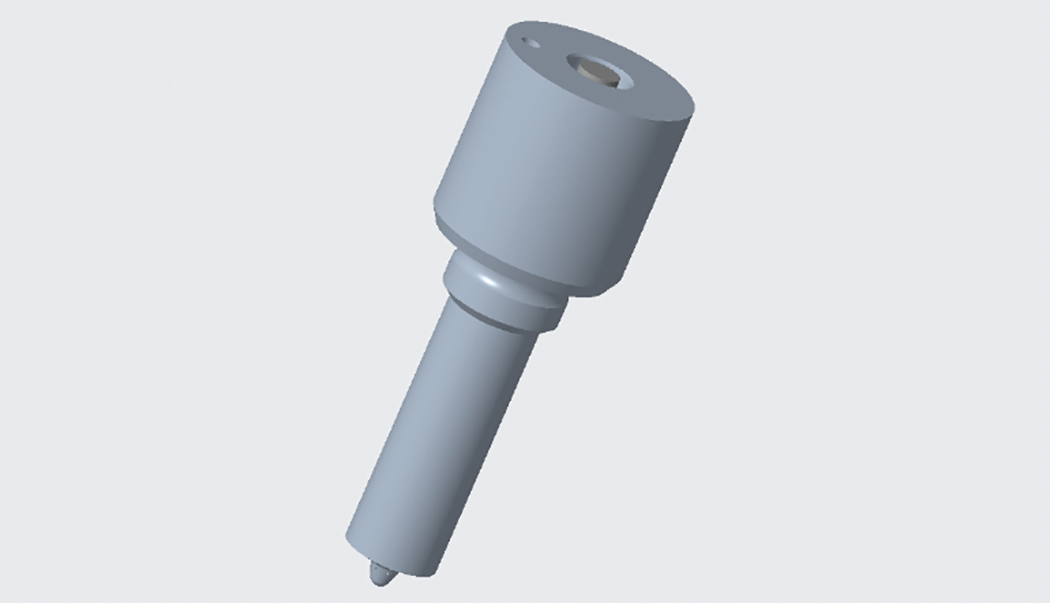
Figure 3: Geometric model of the nozzle
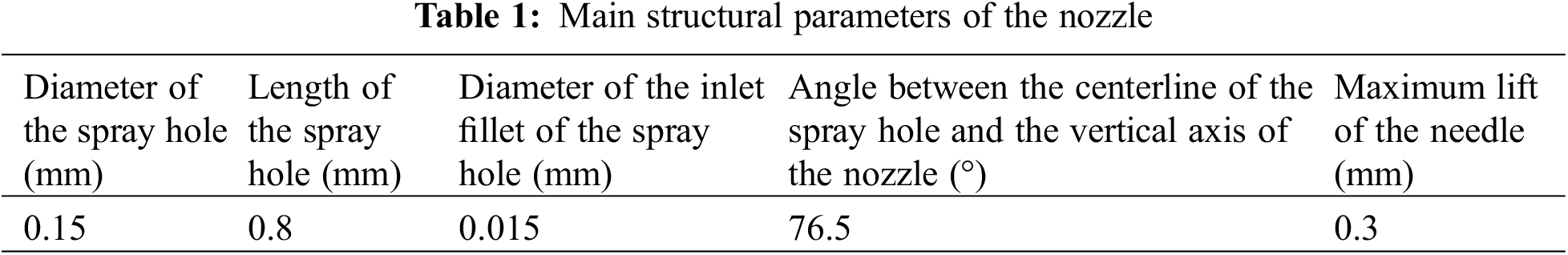
Figure 4: The meshes of the nozzle
The grid-independent verification of the nozzle grid, under an injection pressure of 160 MPa and back pressure of 1.75 MPa, while monitoring the mass flow rate at the outlet of one of the spray holes, with different grid number of the outlet mass flow rate variation law, is shown in Fig. 5. When the number of meshes reached 558505 the calculation results remained basically stable, and at this time it can be considered to have been verified to be grid-independent. On the high-pressure common rail fuel injection test bench, the results of injection mass rate under numerical simulation at different injection pressure are compared with the test data, and the results are shown in Fig. 6. The slight difference between the simulation and test at different injection pressures, which are within an acceptable range, may be due to the gap between physical properties and environmental conditions in the test and simulation. The fuel injection test bench is shown in Fig. 7. Before conducting the test, the test bench was connected to the monitoring bench, and the signal generator was used to simulate the diesel engine speed signal, and the diesel engine speed was changed by adjusting the signal frequency. At the same time, each sensor signal is input to the ECU, and then the ECU drives the actuator according to the pre-stored data, and changes the working condition by changing the potentiometer voltage.
Figure 5: The validation of grid independence

Figure 6: The Validation of injection mass rate
Figure 7: The injection test bench
3 Analysis of Flow Characteristics in the Spray Hole
The injection pressure, spray hole diameter, and the length of the spray hole were selected as simulation variables. Based on the original nozzle structure parameters, the spray hole diameter D was taken as 0.12, 0.18, and 0.20 mm, the spray hole length L was 0.5, 1.2, and 1.5 mm, and the radius of the spray hole inlet fillet r was 0, 0.012 and 0.024 mm.
At the maximum lift of the needle, different injection pressures were selected as the inlet boundary conditions for simulation, and the results of the pressure distribution in the spray hole are shown in Fig. 8. The outlet mass flow rate for a single injection hole is shown in Fig. 9, and the outlet mass flow rate mentioned later is the single-hole mass flow rate, while the non-uniformity of every spray hole will not be considered. The fuel vapor volume fraction at different injection pressures is shown in Fig. 10.

Figure 8: Pressure distribution for different injection pressures

Figure 9: The outlet mass flow rate at different injection pressures
Figure 10: The fuel vapor volume fraction at different injection pressures
Under various pressure conditions, at 120 MPa, there is formation of a very small negative pressure area at the inlet of the spray hole, and with the increase in injection pressure, the negative pressure value decreases significantly. The distribution of the area of negative pressure also increases as the pressure continues to become larger, extending to the outlet [18]. When the injection pressure increases, the fuel flow velocity accelerates, and when the flow reaches the entrance of the spray hole, the effective flow area is greatly reduced, the fuel flow velocity increases further, and the static pressure decreases, resulting in cavitation forming more easily upstream of the spray hole [19].
As shown in Fig. 9, when the injection pressure increases, the outlet mass flow rate gradually increases, and when the injection pressure increases from 120 to 180 MPa, the outlet mass flow rate increases by 23.19%, indicating that increasing the injection pressure is beneficial to increasing the fuel injection mass. This is due to the increase in injection pressure as the jet velocity becomes larger and the mass flow rate through the outlet of the spray hole increases.
As shown in Fig. 10, when the needle is at the maximum lift position, the cavitations at different injection pressures have developed into super-cavitation flow, and all have extended to the outlet of the spray hole. However, the distribution of fuel vapor and its volume fraction at each pressure is almost the same, and the difference in fuel vapor volume fraction at different pressures is not significant, indicating that a super-cavitation flow has been formed in the spray hole at this time. After the formation of the super-cavitation flow, increasing the injection pressure for the cavitation forming has no effect.
Keeping all other structures of the nozzle unchanged, and with the injection pressures all set to 160 MPa, the results of pressure distribution, outlet mass flow rate, and fuel vapor volume fraction calculated by selecting different orifice diameters for the analysis are shown in Figs. 11–13.
Figure 11: The pressure distribution for different diameters of spray hole
Figure 12: The outlet mass flow rate at different diameter of spray hole

Figure 13: The fuel vapor volume fraction at different spray hole diameters
Under the various spray hole diameter scheme, the negative pressure area at D = 0.10 mm only appears at the corner of the spray hole inlet, after which the negative pressure zone develops along the upper wall of the spray hole to the outlet of the spray hole. As the diameter increases, the negative pressure value increases, and in the entire region within the small diameter nozzle, pressure is greater than for the large diameter nozzle. This indicates that in the small diameter nozzle, the possibility of negative pressure is greatly reduced, which also makes the cavitation phenomenon less likely to occur in the small diameter nozzle.
As shown in Fig. 12, with the increase in the diameter of the spray hole, the outlet mass flow rate gradually increased. As the diameter of the spray hole increased from 0.10 to 0.20 mm, the outlet mass flow rate increased by 243.23%, indicating that increasing the diameter of the spray hole is conducive to increasing the amount of fuel injection. And due to the existence of cavitation, the effective flow area is reduced, which means that the actual outlet mass flow rate is smaller than the mass flow rate without considering the effect of cavitation.
As shown in Fig. 13, when the needle is at the maximum lift position, the cavitation area gradually becomes larger and thicker as the diameter of the spray hole increases, and the volume fraction of fuel vapor gradually increases. When D = 0.10 mm, there is basically no cavitation phenomenon; when D = 0.12 mm, there is only a small piece of cavitation phenomenon at the entrance of the spray hole, indicating that the cavitation phenomenon is weak at this time; when the diameter of the spray hole is larger, the cavitation phenomenon is significant, and the cavitation development along the wall of the spray hole has progressed to the outlet of the spray hole. The phenomenon indicates that cavitation occurs very easily in the negative pressure region, and from the static pressure distribution law shown in Fig. 11, it is obvious that while using the small diameter of the spray hole for inhibiting cavitation has a significant effect, the outlet mass flow rate will be reduced.
Keeping all other structures of the nozzle unchanged, and with the injection pressures all set to 160 MPa, the results of pressure distribution, outlet mass flow rate, and fuel vapor volume fraction calculated by selecting different lengths of the spray hole for the analysis are shown in Figs. 14–16.

Figure 14: The pressure distribution for different lengths of spray hole

Figure 15: The outlet mass flow rate at different lengths of spray hole
Figure 16: The fuel vapor volume fraction at different lengths of spray hole
With the needle at maximum lift, each spray hole length scheme formed a negative pressure area at the inlet, and the smaller the length of the spray hole, that is, the smaller the length to diameter ratio of the spray hole, the negative pressure area is relatively large, and the greater the pressure gradient within the nozzle. In the small spray hole length, due to the fuel flow process undergoing a smaller energy loss along the wall, there is faster fuel flow, which means that the smaller the static pressure, the greater the pressure gradient.
As shown in Fig. 15, under different spray hole length schemes, the outlet mass flow rate decreases slightly as the spray hole length increases, after which the outlet mass flow rate almost ceases to change, and when the spray hole length increases from 0.3 to 2.0 mm, the outlet mass flow rate decreases by 2.05%, indicating that increasing the spray hole length is not conducive to increasing the fuel injection mass.
In each spray hole length scheme, when the spray hole length L is less than 1.2 mm, super-cavitation flow is formed inside the spray hole, and cavitation develops along the upper wall surface of the spray hole to the outlet of the spray hole. In the short spray hole length, due to the large pressure gradient, cavitation occurs very easily. The fuel vapor volume fraction is also slightly higher than in the long spray hole, which is consistent with the static pressure distribution in Fig. 14, because in the flow of fuel in the long spray hole the loss is greater and the higher static pressure, so the longer the spray hole, the less likely it is for cavitation to develop. Therefore, using longer spray hole lengths can effectively suppress cavitation and improve flow characteristics.
3.4 Inlet Fillet Radius of Spray Hole
Keeping all other structures of the nozzle unchanged, and with the injection pressures all set to 160 MPa, the results of pressure distribution, outlet mass rate, and fuel vapor volume fraction calculated by selecting different fillet radius of the spray hole for the analysis are shown in Figs. 15–19.
Figure 17: The pressure distribution for different fillet radii of spray hole

Figure 18: The outlet mass flow rate at different fillet radii of spray hole

Figure 19: The fuel vapor volume fraction at different fillet radii of spray hole
With the needle at maximum lift, each different nozzle inlet radius scheme forms cavitation at the entrance of the spray hole negative pressure area. When the inlet radius r = 0 mm, because there is no smooth transition, the local loss at the entrance of the spray hole is larger and the pressure gradient is larger. With the increase of the radius of the inlet fillet, the negative pressure zone area has been reduced and the negative pressure value increases.
At different fillet radii of the spray hole, when the inlet radii r increases from 0 to 0.024 mm, the outlet mass flow rate increases from 0.00587 to 0.00709 kg/s, an increase of 20.78%, indicating that increasing the inlet radii increases the outlet mass flow rate.
In each rounding radius scheme, cavitation begins to appear at the entrance of the spray hole and extends along the upper wall surface of the spray hole to the outlet, forming a super-cavitation flow. When r = 0 mm, because there is no rounding transition, the cavitation area is large and thick, occupying almost the entire interior of the spray hole, and the fuel vapor volume fraction is larger; as the radius of the rounding increases, the cavitation is significantly weakened, the cavitation area becomes smaller and thinner, the fuel vapor volume fraction decreases, and the effective flow area of the spray hole increases, so the outlet mass flow rate increases. Therefore, the cavitation phenomenon inside the nozzle with rounding transition is greatly attenuated and the flow characteristics are greatly enhanced.
4 Optimized Structure of Spray Hole
4.1 Orthogonal Design and Range Analysis
The nozzle structure parameters mentioned in this paper have an impact on the flow characteristics of the nozzle, and the nozzle diameter, nozzle length, and inlet rounding radius are selected as the optimization objects, while the outlet mass flow rate and fuel vapor volume are the optimization objectives. The purpose of optimization is to achieve a higher outlet flow rate and a smaller fuel vapor volume fraction inside the nozzle to meet the requirements of diesel engines for dynamics and reliability, and reduce the corrosion and impact on the inner wall of the nozzle caused by cavitation and bubble collapse [20].
To analyze the three factors of spray hole diameter, spray hole length, and inlet rounding radius, each factor is selected at three levels within a reasonable range and designed to L9(34) Orthogonal table. The orthogonal test protocol is presented in Table 2.
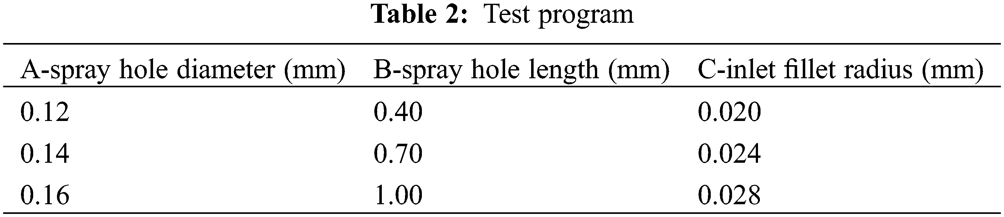
Simulations were performed according to the orthogonal test scheme with the simulation boundary conditions of 160 MPa inlet pressure and 1.75 MPa back pressure. The results are presented in Table 3.
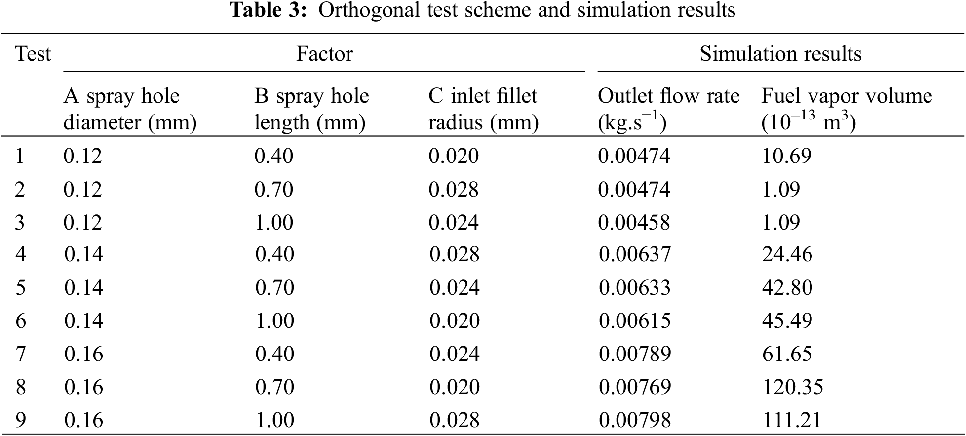
To obtain the optimal design solution, the data were processed using the analysis of range method to derive the order of influence of each factor on the indicators. The results are given in Table 4 after averaging each indicator corresponding to each factor at each level and then finding the range.

From the range of each index in Table 4 with the variety of different factors, we can obtain the magnitude of each index affected by each factor. Outlet mass flow rate is affected by each factor in the order of the spray hole diameter (A), inlet fillet radius (C), and spray hole length (B); fuel vapor volume is affected by each factor in the order of the spray hole diameter (A), inlet fillet radius (C), and spray hole length (B).
For the outlet mass flow rate, the larger the value the better; and for the fuel vapor volume, the smaller the value the better, and the corresponding superior levels of different factors are marked in Table 4. The influence of factor A, spray hole diameter, on the outlet mass flow rate and fuel vapor volume is that with the increase in the diameter of the spray hole, the outlet mass flow rate increases at the same time and the volume of fuel vapor in the nozzle also increases rapidly, consistent with the law shown in Fig. 13.
For the factor A, spray hole diameter, when its value increases from 0.12 mm of A1 to 0.16 mm of A3, the outlet mass flow rate increases by 67.38%, while the fuel vapor volume, due to the very small order of magnitude, gives priority to the effect of the spray hole diameter on the outlet mass flow rate, taking A3 as the optimal level. Consider factor C, inlet rounding radius, the optimal level of outlet mass flow and fuel vapor volume is different, when its value increases from 0.0024 mm of C2 to 0.0028 mm of C3, the outlet mass flow rate increases by 1.44% and fuel vapor volume increases by 29.59%. The inlet rounding radius has a greater impact on fuel vapor volume, so C2 is selected as the optimal level of factor C. In summary, the nozzle structure parameters of the better match for the diameter D = 0.16 mm, length L = 0.4 mm, inlet rounding radius r = 0.024 mm. Because the injection pressure has a greater impact on the flow characteristics and fuel vapor volume in the nozzle. To verify the universality of the optimized structure, the flow characteristics are compared under other injection pressures (140, 160 MPa). The results are presented in Table 5.

Under the standard conditions of 160 MPa injection pressure and 1.75 MPa back pressure, after structural optimization, the nozzle outlet mass flow rate increased by 13.33%, the fuel vapor volume reduced by 33.53%, the nozzle flow characteristics was improved, and the cavitation phenomenon inside the spray hole was weakened.
(1) Spray hole diameter has a huge impact on the flow characteristics of the nozzle and the cavitation phenomenon within the spray hole. As the diameter of the spray hole increases, the outlet mass flow rate increases sharply; when the spray hole diameter increased from 0.10 to 0.20 mm, the outlet mass flow rate increased by 243.23%, while the cavitation within the spray hole increased.
(2) The impact of different spray hole lengths on the outlet mass flow rate is not significant, but different spray hole lengths result in a large difference of the internal pressure gradient of the nozzle. The smaller the length of the spray hole, the larger the negative pressure area in the spray hole, while the greater the pressure gradient, therefore increasing the length of the spray hole is conducive to inhibiting cavitation.
(3) Increasing the inlet rounding radius to improve the flow characteristics of the nozzle also increases the outlet mass flow rate. This positive impact shows that a large radius of the inlet rounding is conducive to reducing the cavitation phenomenon.
(4) Using orthogonal tests and range analysis, the nozzle structure was optimized within a reasonable range of structural parameters. After optimization, the nozzle outlet mass flow rate increased by 13.33%, the fuel vapor volume decreased by 33.53%, the flow characteristics improved, and the intensity of cavitation that occurred was decreased. Also the results at other injection pressures show that the optimized structure has some universality.
Funding Statement: This work was supported by the Shandong Province Key R&D Program (2021CXGC010207).
Conflicts of Interest: The authors declare that they have no conflicts of interest to report regarding the present study.
References
1. Park, S. H., Suh, H. K., Lee, C. S. (2008). Effect of cavitating flow on the flow and fuel atomization characteristics of biodiesel and diesel fuels. Energy & Fuels, 22(1), 605–613. https://doi.org/10.1021/ef7003305 [Google Scholar] [CrossRef]
2. Guerrassi, N., Dupraz, P. (1998). A common rail injection system for high speed direct injection diesel engines. SAE Technical Paper 980803. https://doi.org/10.4271/980803 [Google Scholar] [CrossRef]
3. Sun, K., Hu, X., Li, D., Zhang, G., Zhao, K. (2021). Analysis of bubble behavior in a horizontal rectangular channel under subcooled flow boiling conditions. Fluid Dynamics & Materials Processing, 17(1), 81–95. https://doi.org/10.32604/fdmp.2021.013895 [Google Scholar] [CrossRef]
4. Agarwal, A. K., Singh, A. P., Maurya, R. K., Shukla, P. C., Dhar, A. et al. (2018). Combustion characteristics of a common rail direct injection engine using different fuel injection strategies. International Journal of Thermal Sciences, 134, 475–484. https://doi.org/10.1016/j.ijthermalsci.2018.07.001 [Google Scholar] [CrossRef]
5. Zhang, Z. Y. (2017). Visual experiment of transient cavitating flow in the diesel injector nozzle and its influence on spray characteris (Master Thesis). Jiangsu University, Jiangsu. [Google Scholar]
6. Cristofaro, M., Edelbauer, W., Koukouvinis, P., Gavaises, M. (2020). A numerical study on the effect of cavitation erosion in a diesel injector. Applied Mathematical Modelling, 78, 200–216. https://doi.org/10.1016/j.apm.2019.09.002 [Google Scholar] [CrossRef]
7. Salvador, F. J., Gimeno, J., de la Morena, J., Carreres, M. (2012). Using one-dimensional modeling to analyze the influence of the use of biodiesels on the dynamic behavior of solenoid-operated injectors in common rail systems: Results of the simulations and discussion. Energy Conversion and Management, 54(1), 122–132. https://doi.org/10.1016/j.enconman.2011.10.007 [Google Scholar] [CrossRef]
8. Som, S., Ramirez, A. I., Longman, D. E., Aggarwal, S. K. (2011). Effect of nozzle orifice geometry on spray, combustion, and emission characteristics under diesel engine conditions. Fuel, 90(3), 1267–1276. https://doi.org/10.1016/j.fuel.2010.10.048 [Google Scholar] [CrossRef]
9. He, Z., Zhang, Z., Guo, G., Wang, Q., Leng, X. et al. (2016). Visual experiment of transient cavitating flow characteristics in the real-size diesel injector nozzle. International Communications in Heat and Mass Transfer, 78, 13–20. https://doi.org/10.1016/j.icheatmasstransfer.2016.08.004 [Google Scholar] [CrossRef]
10. Du, Q., Yang, X., Guo, J. (2016). Effects of needle roughness on cavitation in diesel nozzle orifice. Journal of Tianjin University (Science and Technology), 49(7), 749–754. [Google Scholar]
11. Mamaikin, D., Knorsch, T., Rogler, P., Leick, P., Wensing, M. (2017). High speed shadowgraphy of transparent nozzles as an evaluation tool for in-nozzle cavitation behavior of GDI injectors. The 28th European Conference on Liquid Atomization and Spray Systems, Valencia, Spain. Editorial Universitat Politècnica de València. [Google Scholar]
12. Kolade, B., Boghosian, M. E., Reddy, P. S., Gallagher, S. (2003). Development of a general purpose thermal-hydraulic software and its application to fuel injection systems. SAE Technical Papers, 33(7), 1016–1025. https://doi.org/10.4271/2003-01-0702 [Google Scholar] [CrossRef]
13. Wang, J. (2016). Simulation and study of the high-pressure common-rail injection system based on HYDSIM. (Master Thesis). Harbin Engineering University, Harbin, China. [Google Scholar]
14. Deng, Y., Leng, X., Guan, W., He, Z., Long, W. et al. (2022). A numerical study on the in-nozzle cavitating flow and near-field atomization of a spiral hole nozzle using LES-VOF method. Journal of Engineering Thermophysics, 43(9), 2551–2557. [Google Scholar]
15. Soteriou, C., Andrews, R., Smith, M. (1995). Direct injection diesel sprays and the effect of cavitation and hydraulic flip on atomization. SAE Transactions, 128–153. https://doi.org/10.4271/950080 [Google Scholar] [CrossRef]
16. Liu, N., Liu, Z., Gong, X., Huang, X., Xiong, C. (2019). Influence of key structural parameters on fuel injection characteristics of piezoelectric injectors. Transactions of CSICE, 37(2), 139–147. [Google Scholar]
17. Li, D., Zhang, G., Sun, K., Bai, S., Li, G. (2023). CFD-based optimization of a diesel engine waste heat recycle system. Fluid Dynamics & Materials Processing, 19(6), 1479–1493. https://doi.org/10.32604/fdmp.2023.022634 [Google Scholar] [CrossRef]
18. Moro, A., Zhou, Q., Xue, F., Luo, F. (2017). Comparative study of flow characteristics within asymmetric multi hole VCO and SAC nozzles. Energy Conversion and Management, 132, 482–493. https://doi.org/10.1016/j.enconman.2016.11.048 [Google Scholar] [CrossRef]
19. Yamaki, Y., Mori, K., Kamikubo, H., Kohketsu, S., Mori, K. et al. (1994). Application of common rail fuel injection system to a heavy duty diesel engine. SAE Transactions, 1977–1988. https://doi.org/10.4271/942294 [Google Scholar] [CrossRef]
20. Taghavifar, H., Khalilarya, S., Jafarmadar, S. (2014). Diesel engine spray characteristics prediction with hybridized artificial neural network optimized by genetic algorithm. Energy, 71, 656–664. https://doi.org/10.1016/j.energy.2014.05.006 [Google Scholar] [CrossRef]
Cite This Article
 Copyright © 2023 The Author(s). Published by Tech Science Press.
This work is licensed under a Creative Commons Attribution 4.0 International License , which permits unrestricted use, distribution, and reproduction in any medium, provided the original work is properly cited.
 Downloads
 Citation Tools