
 Submit a Paper
 Propose a Special lssue
 Open Access
ARTICLE

Effect of Trapezoidal Obstacle Height and Arrangement Density on the Performance Enhancement of Tri-Serpentine PEMFCs
Mechanical and Automotive Engineering School, Shanghai University of Engineering Science, Shanghai, 201600, China
* Corresponding Author: Hongjuan Ren. Email:
(This article belongs to the Special Issue: Issues of Hydro and Gas Dynamics, Heat and Mass Transfer in Mechanical Engineering and Energy)
Frontiers in Heat and Mass Transfer 2025, 23(3), 921-941. https://doi.org/10.32604/fhmt.2025.066512
Received 10 April 2025; Accepted 26 May 2025; Issue published 30 June 2025
 View Full Text
 Download PDF
Abstract
The flow field architecture of the proton exchange membrane fuel cell (PEMFC) cathode critically determines its performance. To enhance PEMFC operation through structural optimization, trapezoidal obstacles were implemented in the cathode flow channels. The height dependence of these obstacles was systematically investigated, revealing that a 0.7 mm obstacle height enhanced mass transfer from channels to the gas diffusion layer (GDL) compared to conventional triple-serpentine designs. This configuration achieved a 12.08% increase in limiting current density alongside improved water management. Subsequent studies on obstacle distribution density identified 75% density as optimal, delivering maximum net power density with 10.6% lower pressure drop than full-density arrangements.Keywords
Fuel cell technology, recognized as a clean and efficient energy conversion solution [1], demonstrates broad application prospects and significant societal value. This recognition aligns with the growing demand for lightweight, high-performance portable power systems in modern electronics [2]. The technology operates through catalytic electrochemical reactions between hydrogen and oxygen, directly converting chemical energy into electricity while generating thermal energy as a byproduct [3,4]. Distinguished by its high energy density [5,6], zero emissions [7], superior efficiency [8,9], rapid start-up capability [10,11], and environmentally friendly operation with minimal noise, fuel cells are positioned as a pivotal development in future energy systems. Against the backdrop of escalating global environmental concerns and climate change mitigation efforts, conventional fossil fuel-based energy faces increasing restrictions. As an advanced energy conversion platform, fuel cell technology exhibits substantial potential to displace traditional energy sources [12]. Its adoption could effectively reduce fossil fuel dependence, curb greenhouse gas emissions, enhance air quality, and ultimately foster sustainable development [13].
Common PEMFC flow field configurations encompass parallel, serpentine, and interdigitated designs. John et al. [14] demonstrated that parallel flow fields exhibit shorter flow paths and reduced inlet-to-outlet pressure differentials. However, this low-pressure characteristic coupled with multiple parallel reactant pathways promotes liquid water slug formation and subsequent accumulation. To systematically analyze these phenomena, researchers developed a variable-channel-length polymer electrolyte membrane fuel cell (PEMFC) parallel flow field through integrated design, fabrication, and experimental validation. Wang et al. [15] conducted a comparative study on obstacle configuration strategies (positioning and height distribution) in tri-serpentine channel PEMFCs. Their findings revealed that strategically placed obstacles enhance reactant gas transport to the gas diffusion layer (GDL) while extending the operational current density range. Specifically, rear-positioned obstacles achieved optimal reactant uniformity at the GDL/catalyst layer (CL) interface, whereas full-channel obstacle distribution maximized current density output. For automotive PEMFC applications requiring high current density operation, oxygen transport limitations become critical. Interdigitated flow fields demonstrate particular promise in overcoming these constraints through convective transport mechanisms. Tajiri et al. [16] employed spatially resolved current density measurements to characterize the land-channel directional performance of interdigitated flow field PEMFCs, revealing distinct distribution profiles compared to conventional designs. Further investigation using localized oxygen transport resistance measurements via the limiting current density technique across varied oxygen concentrations elucidated the underlying mass transfer mechanisms.
Numerous studies have systematically investigated the influence of flow channel geometry and dimensional parameters (including channel height, width, and channel-to-rib ratio) on PEMFC performance. Xia et al. [17] conducted a comprehensive analysis of channel-to-rib width ratios (CRWR: 1:1 vs. 3:4) and reactant gas relative humidity combinations (80%/80%, 80%/40%, 40%/80%, 40%/40%) on single-cell performance. Their methodology involved polarization/power density curve analysis under varied operating conditions, complemented by electrochemical impedance spectroscopy (EIS) measurements quantifying ohmic resistance, charge transfer resistance, and mass transport resistance. Zhang et al. [18] pioneered a bio-inspired flow channel design mimicking human rib cage morphology, evaluating its performance across different flow patterns and humidity levels. Concurrently, Chen et al. [19] established a two-phase PEMFC model with dead-end anode configuration, elucidating water transport dynamics under synergistic effects of channel orientation and dimensional scaling. Their results indicated that vertically aligned larger channels significantly enhance liquid water expulsion from flow channels to outlets, thereby mitigating performance degradation and water accumulation issues in dead-end anode operation. Innovative channel architectures continue to emerge in PEMFC research. Liu et al. [20] proposed a tapered slope flow field (TSFF), demonstrating through Ansys Fluent simulations that this configuration enhances oxygen distribution uniformity, improves drainage efficiency, and boosts overall cell performance. In a separate advancement, Chen et al. [21] developed a partially separated-partially coupled (PSPC) cathode channel design for PEMFCs with independent cooling channels. Three-dimensional modeling revealed that reduced spacer length (L) in PSPC configurations accelerates cathode-side water removal while optimizing hydrothermal distribution homogeneity. Further progress was achieved by Jin et al. [22], who implemented a condensation tower-inspired curved flow field to enhance air diffusion without auxiliary fans. This design not only compacted the fuel cell architecture but also reduced parasitic power losses. Experimental validation through polarization curves and constant-current discharge tests confirmed improved air diffusion kinetics and overall PEMFC performance.
Recent studies have demonstrated that incorporating obstacles within PEMFC flow channels can enhance reactant transport and overall cell performance. Chen et al. [23] developed a three-dimensional model of a PEMFC with porous obstacles in the flow channels, validating its performance through computational simulations. Their work systematically analyzed how structural parameters of porous obstacles—such as geometry and placement—influence proton exchange membrane fuel cell efficiency. In a complementary approach, Shen et al. [24] investigated cathode flow channel modifications by introducing side blockages. They compared three configurations: conventional straight blockages, alternating side blockages, and hybrid designs combining both. Through numerical simulations, they evaluated the impact of side blockage arrangements on velocity profiles, thermal gradients, reactant distribution, and water management, elucidating the mechanisms behind performance improvements in PEMFCs with these designs. Revisiting serpentine channel optimization, Wang et al. [15] examined obstacle placement strategies (rear versus full-channel) in tri-serpentine configurations. Their results revealed that rear-positioned obstacles achieve optimal reactant uniformity at the gas diffusion layer/catalyst layer (GDL/CL) interface, whereas full-channel obstacle distribution maximizes current density output. Both configurations outperformed conventional channels by enhancing gas transport to the GDL and extending operational current density ranges.
From the above literature, it is evident that the cathode flow field design constitutes a critical factor affecting PEMFC performance. The bipolar plate, being a key component of the PEMFC, features flow channel structures that significantly influence water management, mass transfer, and output characteristics, thereby profoundly impacting overall fuel cell efficiency. The flow fields discussed herein are positioned on the cathode side, as the anode side exhibits negligible effects on cell output performance [25]. Among existing configurations, tri-serpentine PEMFCs demonstrate superior comprehensive performance, though studies incorporating obstacles remain relatively limited [15]. While these investigations provide valuable insights for subsequent researchers, most have overlooked the synergistic relationship between obstacle height and arrangement density. Current findings further indicate that trapezoidal obstacles effectively enhance reactive gas diffusion beneath obstruction zones. However, no systematic study has addressed the combined effects of trapezoidal obstacle height (i.e., obstruction inclination angle) and arrangement density (i.e., number of obstacles per unit length) in triple-serpentine PEMFC configurations. To address this research gap, this study proposes a cathode flow field integrating trapezoidal obstacles within a triple-serpentine PEMFC architecture, building upon prior investigations. We rigorously examine:
1. The influence laws governing trapezoidal obstacle height and arrangement density on PEMFC output performance.
2. Corresponding impacts on oxygen distribution uniformity and liquid water management efficacy.
The serpentine flow channel demonstrates superior mass transfer, enhanced water management, and higher maximum current densities compared to parallel flow channel designs. As one of the most widely adopted flow field configurations in bipolar plates (BPP), serpentine channels are favored for their high overall performance in conventional applications. Relative to single-serpentine configurations, multi-serpentine flow channels exhibit reduced inlet-to-outlet pressure drops and more uniform reactant gas distribution across identical active areas. These advantages render multi-serpentine designs more practical for real-world implementation. However, the inherently slower flow velocity in multi-serpentine structures compared to single-serpentine layouts impedes water removal efficiency [26], posing limitations for practical multi-serpentine PEMFC applications. Trapezoidal cross-sections, extensively utilized in mechanical and civil engineering, optimize stress distribution through their geometric characteristics of parallel top/bottom surfaces and inclined sidewalls. For instance, trapezoidal retaining walls reduce base bending moments by 15%–20% compared to rectangular counterparts—a principle applicable to fuel cell flow field design for minimizing fluid flow pressure losses. In flow channel engineering, sloped trapezoidal structures (wide-top/narrow-bottom cross-sections) enhance reactive gas transport efficiency [20], particularly improving oxygen diffusion through the gas diffusion layer (GDL). Building upon these insights, this study investigates how trapezoidal obstacle height and arrangement density influence mass transfer, water management, and performance enhancement in PEMFCs based on triple-serpentine flow channels. The PEMFC architecture comprises distinct components: anode flow channel, anode gas diffusion layer (GDL), anode catalyst layer, proton exchange membrane, cathode catalyst layer, cathode GDL, and cathode flow channel. Detailed geometric parameters are provided in Table 1. Using 3D numerical simulations, we systematically analyze: The impact of trapezoidal obstacle height on PEMFC output performance; Associated effects on mass transfer and water management. Fig. 1 illustrates the baseline triple-serpentine flow channel geometry and trapezoidal obstacle integration strategy. Four cathode-side obstacle arrangement densities were evaluated (Fig. 2): (a) 25% density; (b) 50% density; (c) 75% density; (d) 100% density.
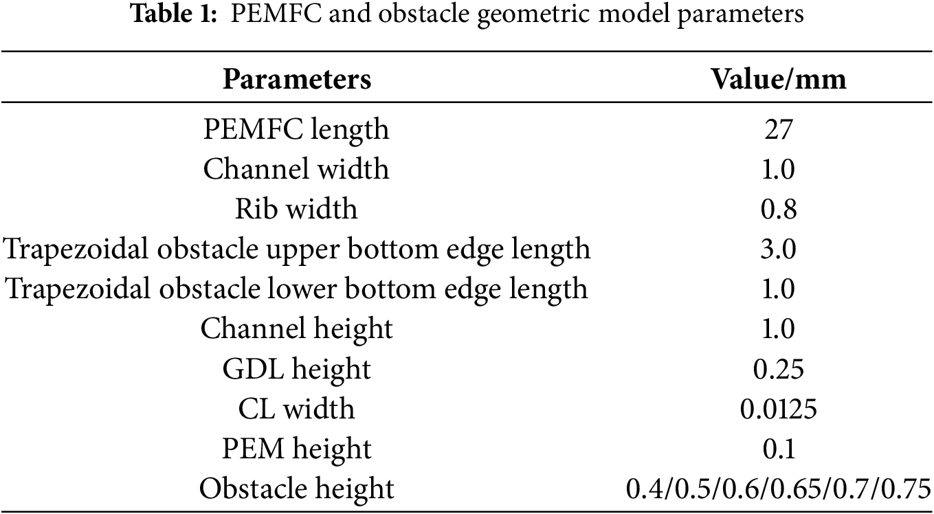
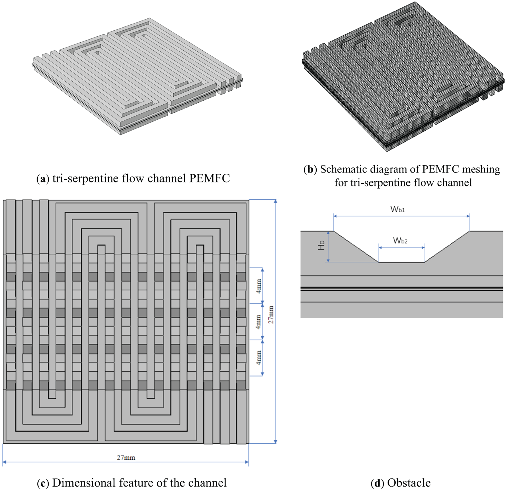
Figure 1: Initial model channels and meshing: (a) Tri-serpentine flow channel PEMFC; (b) Meshed fluid domain; Obstacle flow channel cathode side channel geometry; (c) Dimensional feature and (d) Obstacle
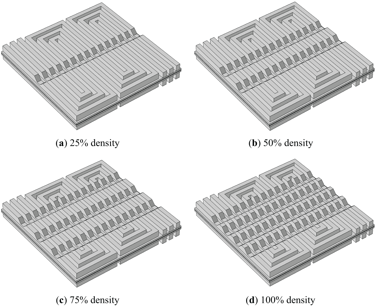
Figure 2: Fluid domains in the presence of four different densities of obstacles in the cathode channel of the PEMFC: (a) 25% density; (b) 50% density; (c) 75% density; (d) 100% density
2.2 Numerical Model and General Settings
In this study, a three-dimensional PEMFC model was developed with the following rational assumptions:
(1) All participating reaction gases behave as ideal gases;
(2) The reacting gases are incompressible;
(3) The gas diffusion layer, catalyst layer, and proton exchange membrane are modeled as isotropic homogeneous porous media;
(4) Gravitational effects are negligible.
Within the electrochemical framework, the electronic charge (c) and ionic charge (
When the cell is neutral, no charge is generated and the current density is given by the following equation:
According to Ohm’s law and Brueggemann’s correction, the effective conductivity could be determined as:
where
where
The voltage between the solid and the membrane is the electrochemical overpotential (
The pressure and the velocity of the reactant gas within BBPs could be calculated upon Navier-Stokes equations, and the related calculations within the GDL together with the CL were relied on Brinkman equations as:
where
where p was pressure, μ was dynamic viscosity, and Ru was the source term of momentum conservation. A porosity (ε) of 0 represented the solid, while a porosity of 1 represented a fluid flowing freely in the channel. Upon Darcy’s law, the source term of momentum conservation for porous media could be expressed with a permeability of K, as:
The convection and the diffusion of the multi-component in CL and GDL were calculated by Maxwell-Stefan equation as:
where
where
The saturated vapor pressure (
Boundary Condition
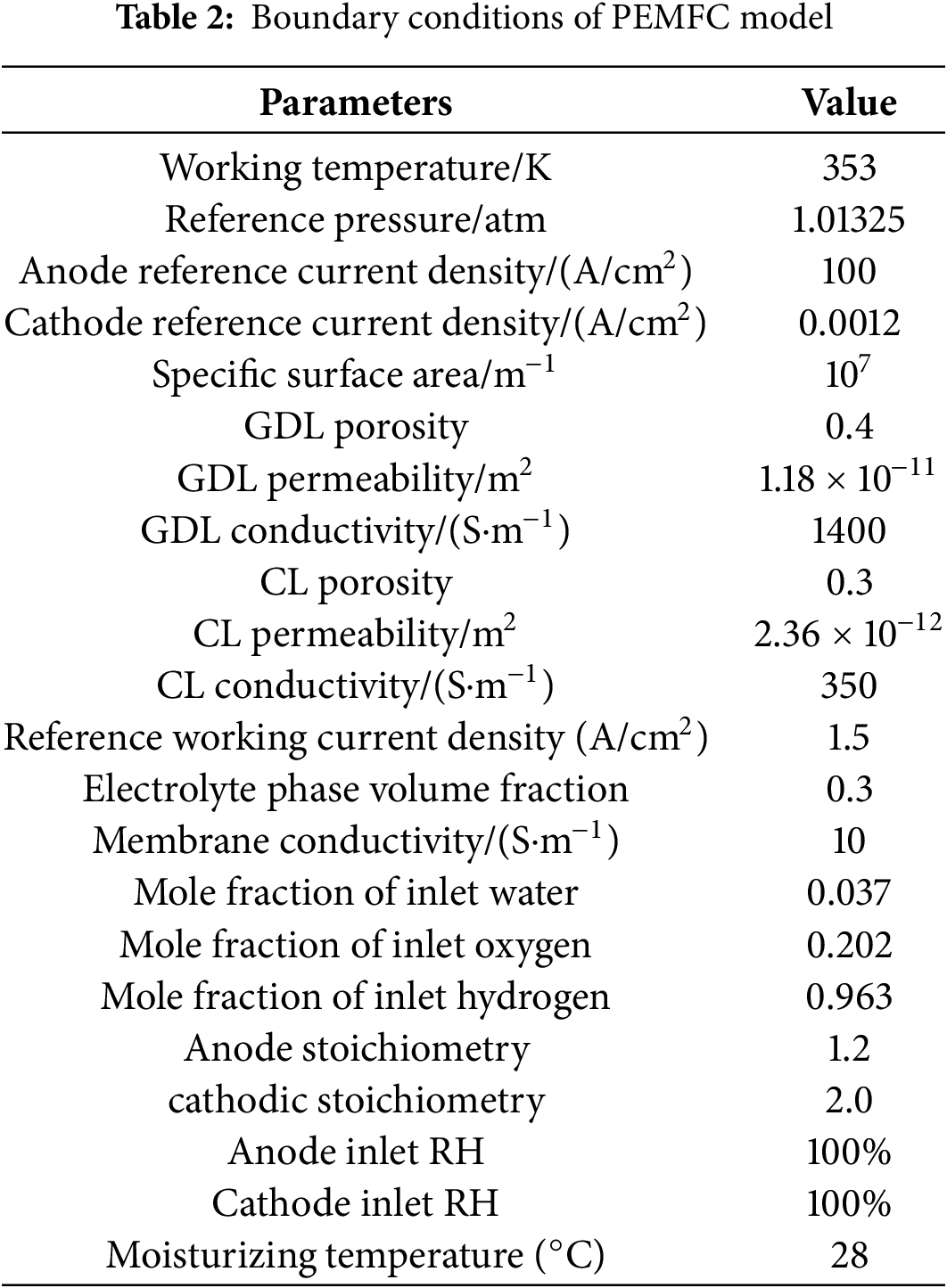
In the simulation, the operating voltage (
The entrance boundary of the cathode channel is the entrance velocity and mole fraction of the reactants (
where
Mesh independence analysis involves verifying the convergence of computational results in numerical simulations by systematically varying mesh density. This process monitors whether solution outputs stabilize during progressive mesh refinement, thereby assessing simulation accuracy and reliability. In numerical modeling, mesh resolution significantly affects computational outcomes: excessively coarse meshes introduce substantial errors, while overly refined meshes waste computational resources. Thus, mesh independence verification is essential for determining optimal discretization parameters.
Using a representative PEMFC operating voltage of 0.6 V, seven mesh configurations were evaluated to assess current density independence from spatial discretization. As Table 3 demonstrates, results converge near 1.34 A/cm2 with decreasing mesh size. Case IV analysis reveals less than 0.1% relative error when exceeding 431,984 mesh elements (Fig. 3). To ensure high-fidelity results, subsequent simulations employed Case IV’s validated configuration (549,821 total elements).
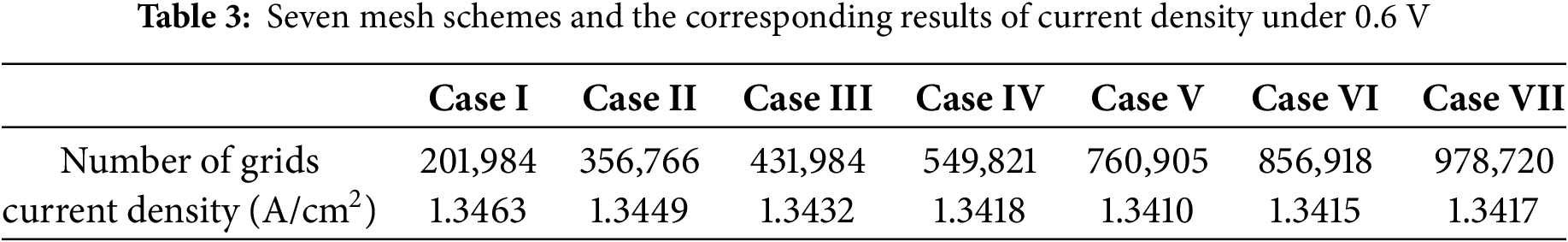
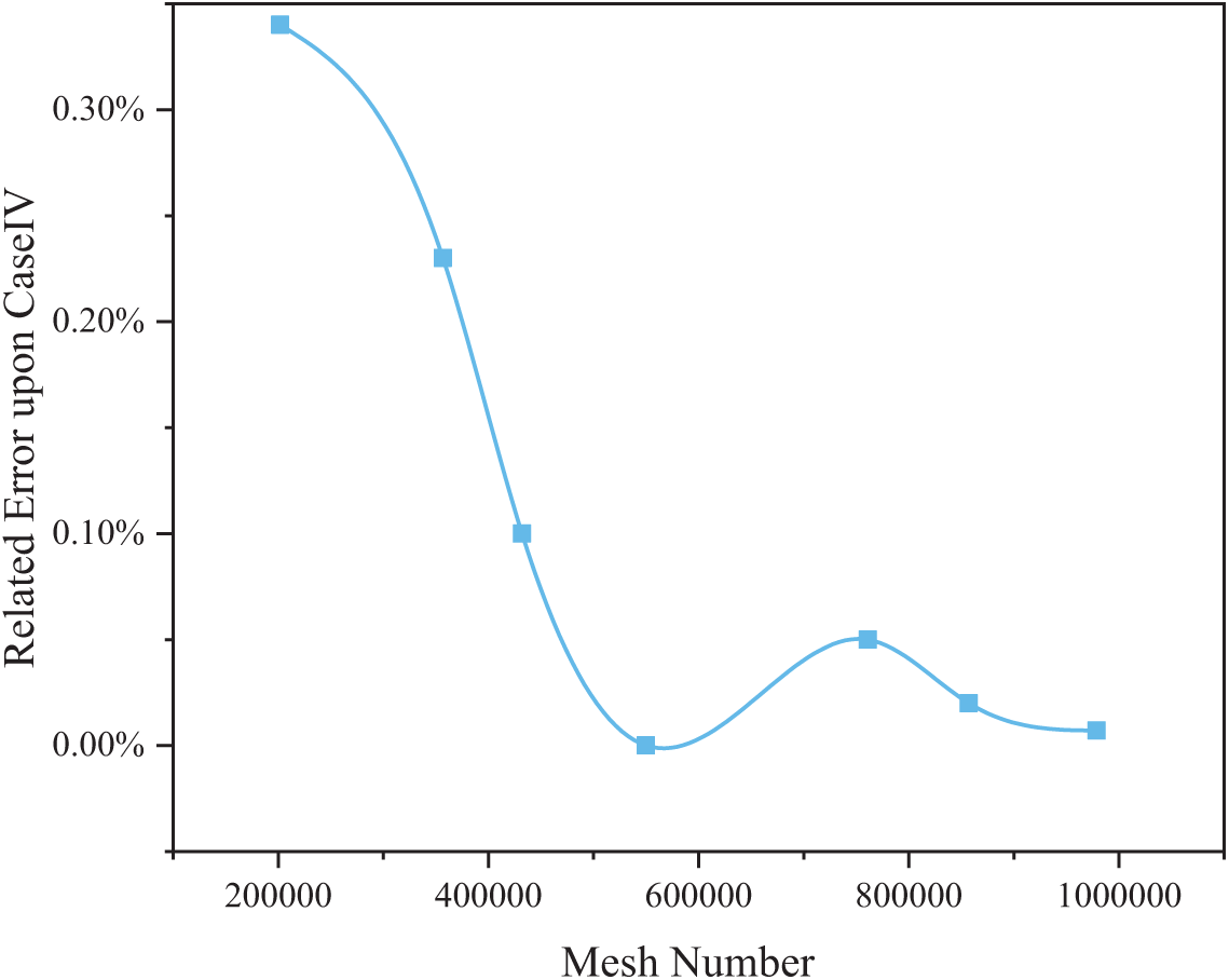
Figure 3: Verification of grid-independence
2.4 Model Results and Validation
To reduce computational complexity and processing time, simulations focused on a single PEMFC unit. This unit comprises the cathode-anode flow channels and the intermediate membrane-electrode assembly between the bipolar plates. The numerical model was developed in COMSOL Multiphysics®, with geometric parameters and boundary conditions identical to those reported by Wang et al. [15], enabling direct validation under equivalent operating conditions. Fig. 4 confirms strong agreement between simulation results and reference experimental data, verifying model fidelity. This validated PEMFC framework (retaining identical physical parameters) was subsequently applied to analyze flow field structural variations. This methodological approach aligns with established practices in computational fuel cell research [27,28].
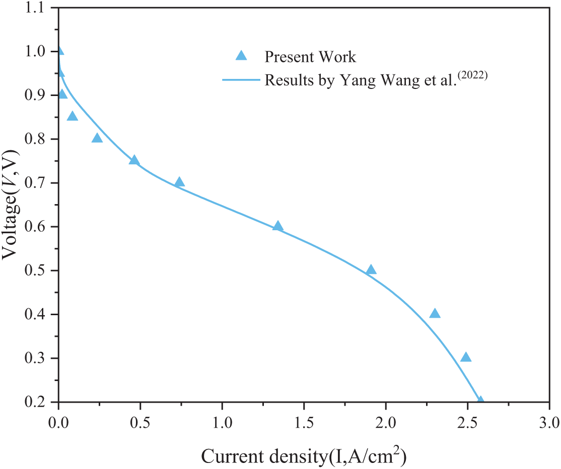
Figure 4: Comparison of polarization curves calculated in this paper with literature [15]
Obstacle height has been demonstrated to significantly influence PEMFC performance [29,30]. To systematically evaluate trapezoidal obstacle effects in tri-serpentine flow channel PEMFCs, this study specifically investigates height-dependent impacts.
A variable-resolution height sampling strategy was implemented: larger increments (0.1 mm) for lower obstacle heights (0.4–0.6 mm range) where performance sensitivity diminishes, transitioning to finer increments (0.05 mm) for critical higher heights (0.6–0.75 mm) to ensure parameter space accuracy. As shown in Fig. 1c, uniformly spaced trapezoidal obstacles (1.0 mm inter-obstacle distance) were arranged column-wise with consistent height per configuration.
Fig. 5 shows the polarization curves of the PEMFC for different obstacle heights. The basic pattern of polarization is not altered by the presence of obstacles, indicating that the electrochemical reaction principles within the PEMFC remain the same. However, the obstacles in the cathode-side channel greatly increase the ability to generate current density compared to the conventional tri-serpentine flow channel.
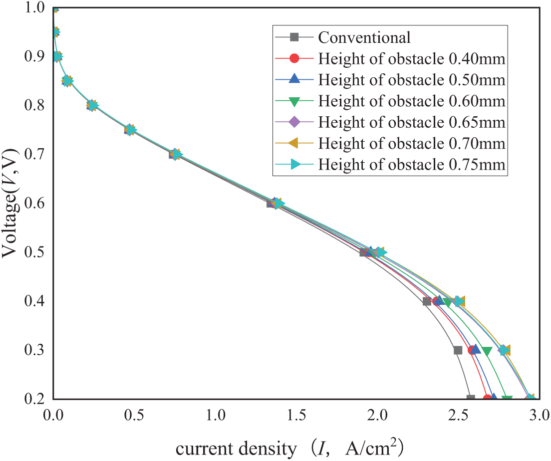
Figure 5: Effect of trapezoidal obstacle height on polarization curves
At higher operating voltages (e.g., greater than 0.7 V), the height of the obstacle arrangement does not have a significant effect on the current density because the current density generated is too low to reflect this change. As the operating voltage decreases and the current density increases, the presence of obstacles has a more significant effect on the enhancement of the PEMFC; however, different obstacle heights result in different levels of enhancement.
Compared to the conventional tri-serpentine channel, the improvement in current density due to trapezoidal obstacles increases with the increase in obstacle height (≤0.70 mm) and minimizes when the obstacle height is greater than 0.65 mm. This may be due to the fact that the presence of obstacles greatly forces the reacting gases to flow towards the GDL and CL instead of high degree of freedom downward, which leads to enhanced electrochemical reactions, but too high obstacles increase the pressure drop in the flow channel, which affects the performance of the PEMFC; at the same time, forced mass transfer occurs throughout the flow channel. As the reactant gas flows along the channel, the concentration of the reactant gas gradually decreases and the PEMFC reacts more vigorously near the inlet, and the area near the channel inlet is a highly active region for the PEMFC; therefore, the level of mass-transfer enhancement is weaker for the GDL and CL at the outlet of the channel (than that near the channel inlet).
Fig. 6 illustrates the influence of trapezoidal obstacle height on PEMFC power density. For all tested obstacle heights, the power density profiles exhibit a consistent trend: rising to a peak before declining with increasing current density. As obstacle height increases (≤0.7 mm), power density at any given current density improves (though less noticeably at low current densities <1.0 A/cm2), with both maximum power density and its corresponding current density demonstrating monotonic enhancement. The optimal performance occurs at 0.7 mm obstacle height, yielding a 35% power density increase compared to conventional channels at 2.5 A/cm2. Notably, this enhancement diminishes slightly at 0.75 mm height. Such substantial improvements highlight the design’s potential for practical PEMFC applications.
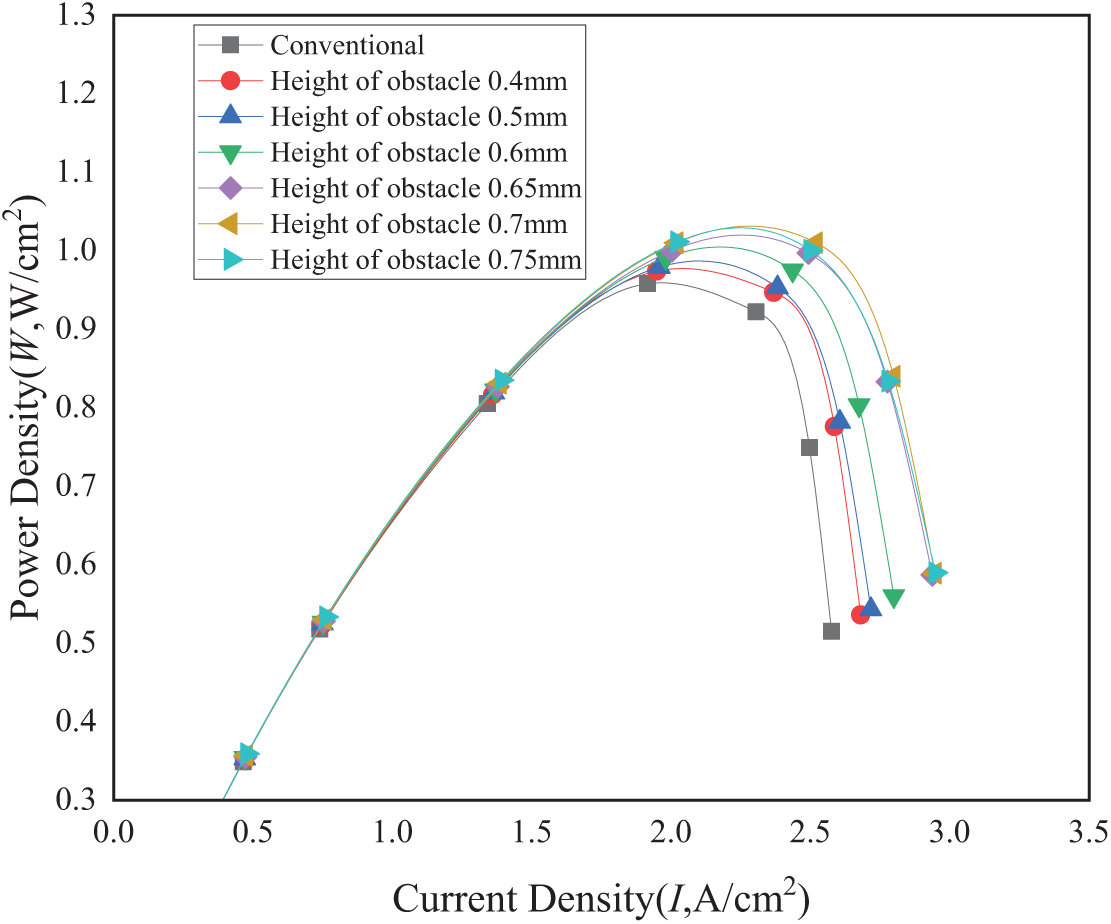
Figure 6: Effect of trapezoidal obstacle height on power density
Fig. 7 displays the oxygen concentration (mole fraction) distribution at the GDL/CL interface under a constant operating voltage of 0.6 V. The incorporation of trapezoidal obstacles substantially enhances reactant mass transfer, particularly in the channel outlet region. Oxygen concentration progressively decreases along the flow path from inlet to outlet due to sustained electrochemical reactions and under-rib convection induced by counter-flow gas interactions in adjacent channels. This phenomenon underscores the critical need to optimize reactant availability in outlet regions to sustain cell reactions.
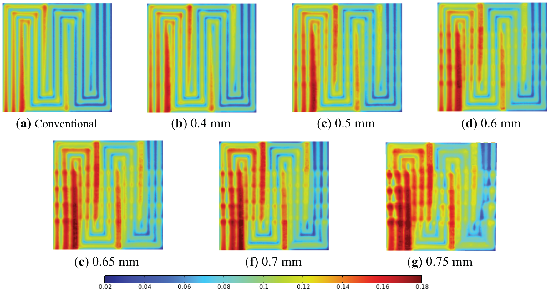
Figure 7: Distribution of oxygen (mole fraction) within the GDL/CL interface near the cathode of the PEMFC at different obstacle heights at a voltage of 0.6 V: (a) Conventional; (b) 0.4 mm; (c) 0.5 mm; (d) 0.6 mm; (e) 0.65 mm; (f) 0.7 mm; (g) 0.75 mm
Fig. 8 illustrates the water mole fraction distribution at the GDL/CL interface under identical 0.6 V operation. Continuous water generation along the channel leads to progressive accumulation toward the outlet, driven by convective gas flow. Counter-flow dynamics between neighboring channels create enhanced inter-channel convection through elevated pressure differentials, while accelerated gas flow toward the CL promotes water removal from the CL through the GDL into the channel. Consequently, water concentration in these regions remains markedly lower than elsewhere, effectively mitigating flooding effects. Compared to conventional triple-serpentine designs, trapezoidal obstacles significantly alleviate water flooding—particularly in under-convection zones—with water management efficacy improving proportionally with obstacle height (≤0.7 mm).
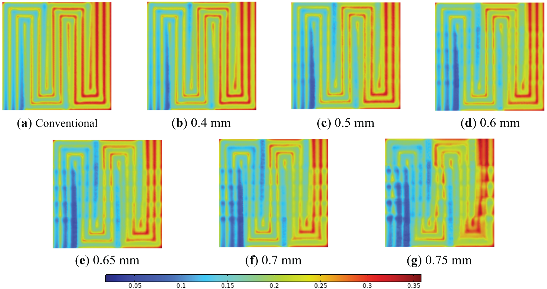
Figure 8: Distribution of water (mole fraction) within the GDL/CL interface near the cathode of the PEMFC at different obstacle heights at a voltage of 0.6 V: (a) Conventional; (b) 0.4 mm; (c) 0.5 mm; (d) 0.6 mm; (e) 0.65 mm; (f) 0.7 mm; (g) 0.75 mm
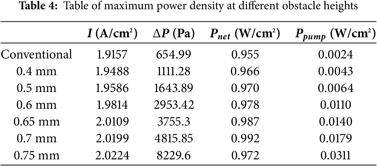
The pressure drop in a PEMFC is a critical metric for evaluating flow field structural integrity and directly correlates with parasitic pumping losses. Excessive pressure drop reduces operational power output and compromises system efficiency. Fig. 9 illustrates the cathode flow field inlet-outlet pressure drop profiles across varying obstacle heights. As shown, the pressure drop gradually increases with obstacle height elevation (i.e., under rising current density conditions). At an obstacle height of 0.75 mm, the pressure drop escalates significantly, offsetting potential power density improvements. Comparative analysis of polarization and power density curves confirms optimal performance at a 0.7 mm obstacle height, where the pressure drop remains sufficiently low to maintain cell efficiency. Notably, elevated pressure drops not only increase parasitic pumping power but also jeopardize PEMFC longevity by accelerating component degradation. As demonstrated in Table 4 (net power analysis), a 0.7 mm obstacle height achieves maximum net power density, validating this configuration’s superior balance of hydraulic resistance and electrochemical performance.
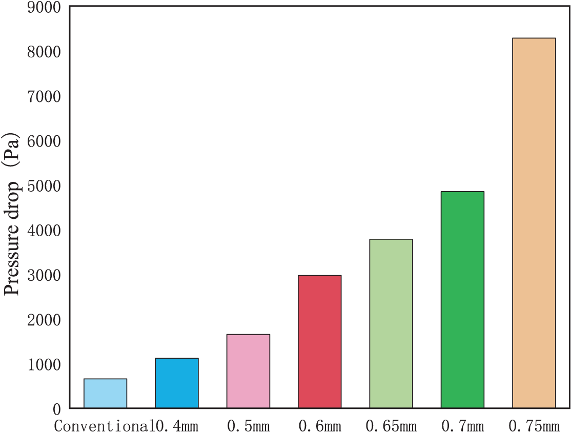
Figure 9: Comparison of pressure drop at different obstacle heights
The net power density (
where
3.2 Effect of Obstacle Distribution Density
Based on the optimized model from previous analyses, the PEMFC demonstrates enhanced overall performance with trapezoidal obstacles. At the optimal obstacle height of 0.7 mm, the baseline configuration with uniformly distributed obstacles across the symmetric flow channel region (Fig. 2) is defined as 100% arrangement density. This corresponds to four obstacles per column within the designated channel range. Four distinct arrangement densities were evaluated: Case I (25% density); Case II (50% density); Case III (75% density); Case IV (100% density).
Figs. 10 and 11 present the polarization and power density curves for these configurations. All obstacle-enhanced cases outperform the conventional design, with performance improvements escalating as arrangement density increases. Notably, Case III (75% density) achieves comparable current and power densities to Case IV (100% density), suggesting reactant oversaturation near the inlet at high densities (as evidenced in Fig. 11 by oxygen distribution patterns). While excessive inlet-region density may not further enhance performance, obstacles near the outlet remain critical for redirecting oxygen-depleted gas toward the catalyst layer (CL), thereby sustaining electrochemical reactions.
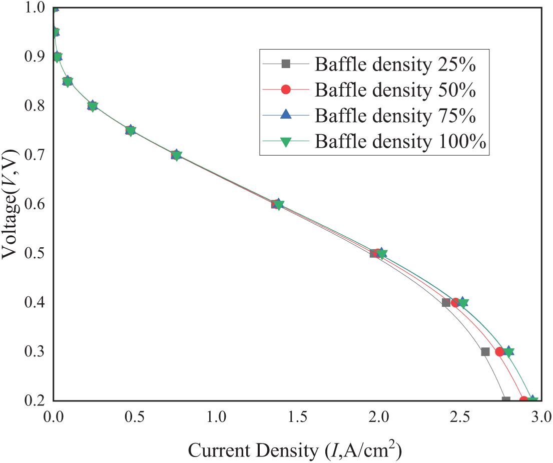
Figure 10: Effect of density of trapezoidal obstacle arrangement on polarization curves
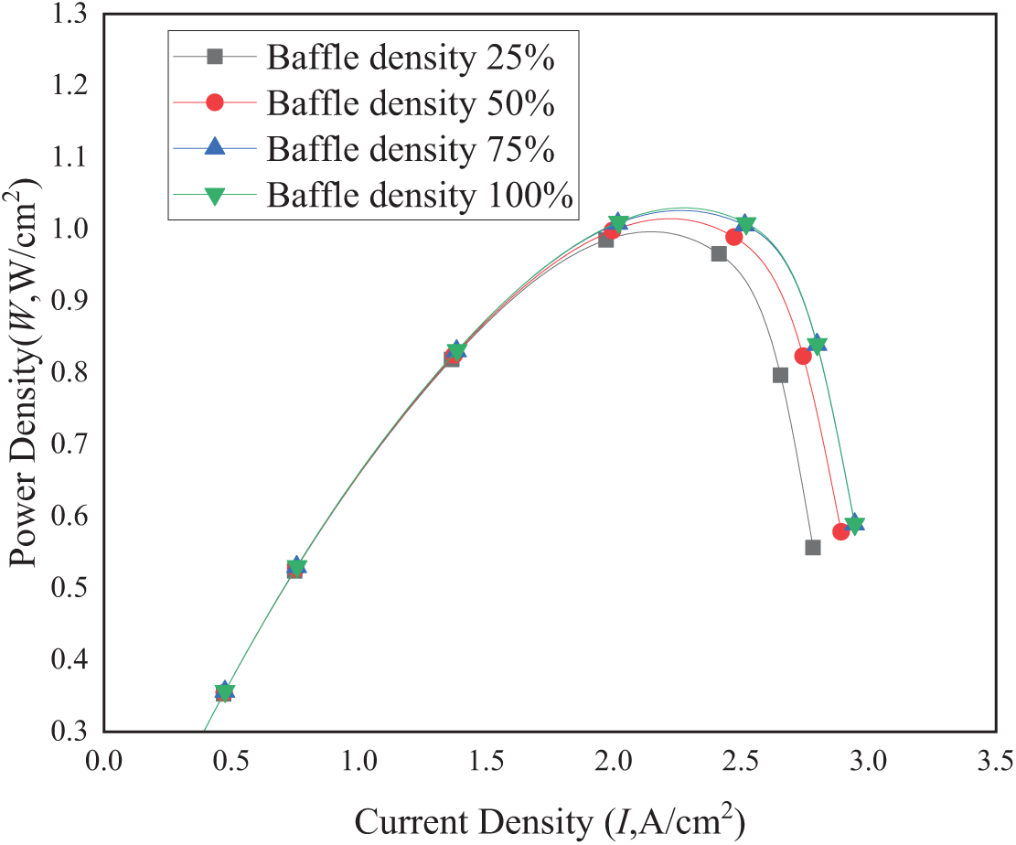
Figure 11: Effect of density of trapezoidal obstacle arrangement on power density
As shown in Fig. 12, oxygen concentration gradually decreases along the channel from inlet to outlet due to continuous consumption by electrochemical reactions, whereas the concentration significantly increases near obstacle placement regions. This enhancement is most pronounced between adjacent channels with opposing reactant gas flow directions, likely attributable to elevated pressure drops in these zones, which enhance oxygen diffusion into the catalyst layer (CL). Obstacles amplify pressure differentials between neighboring channels, intensifying under-rib convection—an effect particularly notable at arrangement densities exceeding 75%. Critically, obstacles proximal to the outlet redirect oxygen-depleted gas (lower mole fraction) toward the CL, sustaining electrochemical activity.
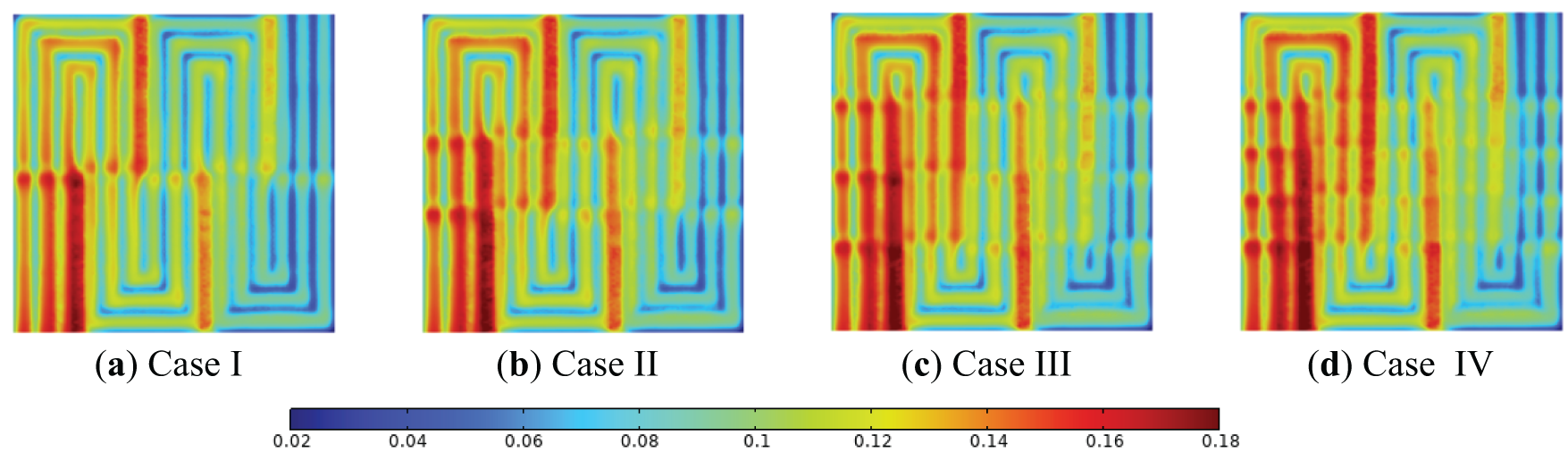
Figure 12: Distribution of oxygen (mole fraction) within the GDL/CL interface near the cathode of PEMFC at different arrangement densities at a voltage of 0.6 V: (a) Case I; (b) Case II; (c) Case III; (d) Case IV
Notably, PEMFCs with low obstacle density near the outlet exhibit severe oxygen depletion, significantly impairing performance. Fig. 11 reveals that low obstacle density configurations display extensive oxygen-deficient zones at the outlet, while high-density arrangements markedly improve oxygen availability in these regions. These trends correlate directly with flow field mass transfer dynamics. In high-density configurations, outlet-proximate obstacles effectively drive oxygen-deficient gas toward the CL. Conversely, sparse outlet obstacles disproportionately intensify inlet reactions, exacerbating oxygen depletion and inducing non-uniform concentration gradients downstream.
As current density increases, oxygen consumption escalates, progressively worsening rear-channel oxygen deficiency. To optimize PEMFC performance, maintaining sufficient oxygen concentration at the channel’s rear section necessitates higher obstacle density in these regions.
Fig. 13 illustrates the water mole fraction distribution at the GDL-CL interface under a constant operating voltage of 0.6 V. Continuous water generation along the channel during electrochemical reactions leads to progressive accumulation toward the outlet, driven by convective gas flow. In regions between adjacent channels with opposing gas flow directions, enhanced under-rib convection and increased gas flow velocity toward the catalyst layer (CL) accelerate water removal from the CL through the GDL into the channel. Consequently, water concentration in these zones remains markedly lower than in other regions, effectively suppressing flooding effects.
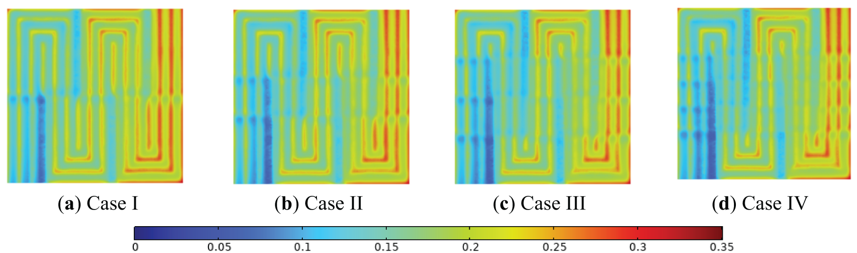
Figure 13: Distribution of water (mole fraction) within the GDL/CL interface near the cathode of PEMFC at different arrangement densities at a voltage of 0.6 V: (a) Case I; (b) Case II; (c) Case III; (d) Case IV
Compared to conventional tri-serpentine PEMFCs, trapezoidal obstacles significantly mitigate water flooding. At obstacle arrangement densities exceeding 75%, water mole fractions in counter-flow channel regions are substantially reduced compared to baseline designs, further alleviating flooding risks.
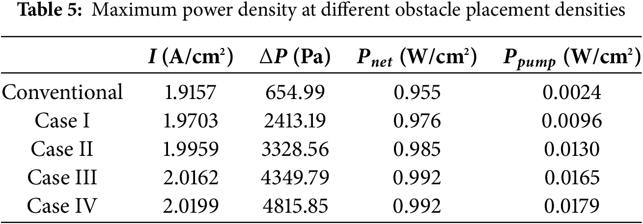
Fig. 14 compares the inlet-outlet pressure drop of the cathode flow field across different obstacle arrangement densities. As illustrated in Fig. 14, the pressure drop escalates proportionally with increasing arrangement density. The PEMFC achieves its maximum limiting current density at 75% density, while reducing the pressure drop by 10.6% compared to the 100% density configuration. Combined with the net power density data in Table 5, the 75% arrangement density yields peak net power density, establishing it as the optimal configuration.
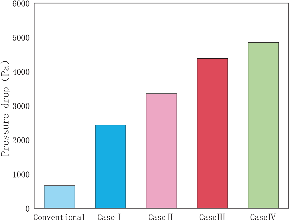
Figure 14: Pressure drop curve at different obstacle arrangement densities
In this study, the height and arrangement density of trapezoidal obstacles in the cathode flow channel were numerically analyzed. Their impacts on enhancing output performance, reactant mass transfer, and water management in tri-serpentine PEMFCs were systematically evaluated, with the following key conclusions:
Compared with the conventional tri-serpentine PEMFC, the maximum net power density of the trapezoidal barrier with a height of 0.7 mm in the channel was improved by 3.84%; the power density was improved by about 35% at the same current density; and the mass transfer and moisture management effects were also improved.
For different barrier arrangement densities, the increase in current density and power density was greater at higher barrier densities compared to the conventional serpentine flow field. The effect was most pronounced when the barrier arrangement density was 75%, with the highest net power density; and the pressure drop was reduced by 10.6% compared to the PEMFC with 100% arrangement density. Mass transfer and water management were also superior.
Acknowledgement: The authors extend their sincere gratitude to the team. Without their assistance and encouragement, this research would not have been completed.
Funding Statement: The authors received no specific funding for this study.
Author Contributions: All authors contributed to the study conception and design. Material preparation, data collection and manuscript writing were all completed by Hongen Li. Data analysis and final review of the manuscript were completed by Hongjuan Ren, Cong Li and Yecui Yan. All authors reviewed the results and approved the final version of the manuscript.
Availability of Data and Materials: All data, models, or code that support the findings of this study are available from the corresponding author upon reasonable request.
Ethics Approval: Not applicable.
Conflicts of Interest: The authors declare no conflicts of interest to report regarding the present study.
Nomenclature
| PEMFC length | |
| Channel width | |
| Rib width | |
| Trapezoidal obstacle upper bottom edge length | |
| Trapezoidal obstacle lower bottom edge length | |
| Channel height | |
| GDL height | |
| CL width | |
| PEM height | |
| obstacle height | |
| Electrolyte current density | |
| Current source | |
| Electrolyte conductivity | |
| Electrolyte potential | |
| Electrolyte current density | |
| Current source | |
| Electrolyte conductivity | |
| Electrolyte potential | |
| Electrolyte conductivity in the porous electrode | |
| Electrode conductivity in the porous electrode | |
| Reaction source of the electrode | |
| Active specific surface area | |
| Current density of the cell | |
| Anode transfer coefficients | |
| Cathode transfer coefficients | |
| F | Faraday constant |
| Overpotential | |
| P (Pa) | Pressure |
| Dynamic viscosity | |
| Source term of momentum | |
| Porosity | |
| K | Permeability |
| Source term of species | |
| Mass fraction | |
| Diffusive flux of species | |
| Diffusivity | |
| Mole fraction | |
| Saturation pressure of water | |
| Operating voltage | |
| Anode channel inlet speed | |
| Water molar fraction of anode reactants | |
| Molar fraction of hydrogen in anode reactants | |
| Cathode channel inlet speed | |
| λ | Stoichiometric ratio |
| Reference working current density | |
| Activated area of the cell | |
| Cross-sectional area of the channel | |
| Molar fraction of oxygen in cathode reactants | |
| Molar fraction of nitrogen in cathode reactants | |
| T (K) | Working temperature |
| Reference pressure | |
| Anode reference current density | |
| Cathode reference current density | |
| Active specific surface area | |
| GDL porosity | |
| GDL permeability | |
| GDL conductivity | |
| CL porosity | |
| (m2) CL penetrance | |
| CL conductivity | |
| Reference working current density | |
| Electrolyte phase volume fraction | |
| PEM conductivity | |
| Anode stoichiometry | |
| Cathodic stoichiometry | |
| Anode inlet RH | |
| Cathode inlet RH | |
| Moisturizing temperature |
References
1. Zhu T, Yang Y, Liu Y, Lopez-Hallman R, Ma Z, Liu L, et al. Wireless portable light-weight self-charging power packs by perovskite-organic tandem solar cells integrated with solid-state asymmetric supercapacitors. Nano Energy. 2020;78:78105397. doi:10.1016/j.nanoen.2020.105397. [Google Scholar] [CrossRef]
2. Wang YC, Ren HJ, Li C. Enhancing proton-exchange membrane fuel-cell heat transfer performance with embedded cooling channel design: a systematic numerical study. J Energy Eng. 2024;150(1):04023052. doi:10.1061/jleed9.eyeng-5099. [Google Scholar] [CrossRef]
3. Wang Y, Zhang J, Liu Z. Carbothermic reduction reactions at the metal-slag interface in ti-bearing slag from a blast furnace. JOM. 2017;69(11):2397–403. doi:10.1007/s11837-017-2508-2. [Google Scholar] [CrossRef]
4. Saminathan J, Marappan M, Angappamudaliar Palanisamy SK, Ramasamy S. Performance improvement of proton exchange membrane fuel cell by modified flow field design. J Energy Eng. 2023;149(5):04023034. doi:10.1061/jleed9.eyeng-4863. [Google Scholar] [CrossRef]
5. Ebrahimi S, Roshandel R, Vijayaraghavan K. Power density optimization of PEMFC cathode with non-uniform catalyst layer by Simplex method and numerical simulation. Int J Hydrogen Energy. 2016;41(47):22260–73. doi:10.1016/j.ijhydene.2016.07.247. [Google Scholar] [CrossRef]
6. Ning F, He X, Shen Y, Jin H, Li Q, Li D, et al. Flexible and lightweight fuel cell with high specific power density. ACS Nano. 2017;11(6):5982–91. doi:10.1021/acsnano.7b01880. [Google Scholar] [PubMed] [CrossRef]
7. Lin P, Wang H, Wang G, Li J, Yang G, Li S, et al. Design of a novel multidimensional forced-convections flow channel with both blockages and under-rib channels for PEMFC. J Energy Eng. 2023;149(5):04023031. doi:10.1061/jleed9.eyeng-4914. [Google Scholar] [CrossRef]
8. Zhang J, Hu Y. Sealing performance and mechanical behavior of PEMFCs sealing system based on thermodynamic coupling. Int J Hydrogen Energy. 2020;45(43):23480–9. doi:10.1016/j.ijhydene.2020.06.167. [Google Scholar] [CrossRef]
9. Lakshmi BR, Harikrishnan N, Juliet VA. Comparative analysis of 2D and 3D model of a PEMFC in COMSOL. Appl Surf Sci. 2017;418(1):99–102. doi:10.1016/j.apsusc.2017.02.125. [Google Scholar] [CrossRef]
10. Chen X, Chen Y, Liu Q, Xu J, Liu Q, Li W, et al. Performance study on a stepped flow field design for bipolar plate in PEMFC. Energy Rep. 2021;7(35):336–47. doi:10.1016/j.egyr.2021.01.003. [Google Scholar] [CrossRef]
11. Qu L, Wang Z, Guo X, Song W, Xie F, He L, et al. Effect of electrode Pt-loading and cathode flow-field plate type on the degradation of PEMFC. J Energy Chem. 2019;35(26):95–103. doi:10.1016/j.jechem.2018.09.004. [Google Scholar] [CrossRef]
12. Song Y, Zhang C, Deshpande A. Fixed air flow-rate selection by considering the self-regulating function of low power air-cooled PEMFC stack. Int J Heat Mass Transf. 2020;158:119771. doi:10.1016/j.ijheatmasstransfer.2020.119771. [Google Scholar] [CrossRef]
13. Saman HK, Qamar A, Klaus R. Electrochemical aspects of interconnect materials in PEMFCs. Int J Hydrogen Energy. 2021;46(71):35420–47. doi:10.1016/j.ijhydene.2021.08.105. [Google Scholar] [CrossRef]
14. Bachman J, Charvet M, Santamaria A. Experimental investigation of the effect of channel length on performance and water accumulation in a PEMFC parallel flow field. Int J Hydrogen Energy. 2012;37(22):17172–9. doi:10.1016/j.ijhydene.2012.08.023. [Google Scholar] [CrossRef]
15. Wang Y, Sun ZY, Yang L. Enhancement effects of the obstacle arrangement and gradient height distribution in serpentine flow-field on the performances of a PEMFC. Energy Convers Manag. 2022;252:115077. doi:10.1016/j.enconman.2021.115077. [Google Scholar] [CrossRef]
16. Tajiri K, Karani J, Shrivastava NU. Experimental study of oxygen transport mechanisms in PEMFC interdigitated flow field. J Electrochem Soc. 2018;165(16):F1385–91. doi:10.1149/2.0021902jes. [Google Scholar] [CrossRef]
17. Xia Z, Chen H, Zhang T, Pei P. Effect of channel-rib width ratio and relative humidity on performance of a single serpentine PEMFC based on electrochemical impedance spectroscopy. Int J Hydrogen Energy. 2022;47(26):13076–86. doi:10.1016/j.ijhydene.2022.02.047. [Google Scholar] [CrossRef]
18. Zhang S, Yang Q, Xu H, Mao Y. Numerical investigation on the performance of PEMFC with rib-like flow channels. Int J Hydrogen Energy. 2022;47(85):36254–63. doi:10.1016/j.ijhydene.2022.08.185. [Google Scholar] [CrossRef]
19. Ben C, Qi L, Cheng Z. Numerical study on water transfer characteristics under joint effect of placement orientation and flow channel size for PEMFC with dead-ended anode. Energy. 2022;254(5):124365. doi:10.1016/j.energy.2022.124365. [Google Scholar] [CrossRef]
20. Liu M, Huang H, Li X, Guo X, Wang T, Lei H. Geometry optimization and performance analysis of a new tapered slope cathode flow field for PEMFC. Int J Hydrogen Energy. 2021;46(75):37379–92. doi:10.1016/j.ijhydene.2021.09.022. [Google Scholar] [CrossRef]
21. Chen C, Wang C, Zhang Z. A novel channel design and heat and mass transfer analysis of fuel cells. Energy Convers Manag. 2022;254(36):115273. doi:10.1016/j.enconman.2022.115273. [Google Scholar] [CrossRef]
22. Jin H, Zou S, Wen Q, Li Y, Ning F, Xu P, et al. Performance improvement of air-breathing proton exchange membrane fuel cell (PEMFC) with a condensing-tower-like curved flow field. Chin Chem Lett. 2023;34(4):107441. doi:10.1016/j.cclet.2022.04.039. [Google Scholar] [CrossRef]
23. Chen C, Xuan D, Wu M, Liu S, Shen Y. Performance and parameter sensitivity analysis of the PEMFC flow channel with porous baffles. Appl Sci. 2021;11(24):11942. doi:10.3390/app112411942. [Google Scholar] [CrossRef]
24. Shen J, Du C, Yan F, Chen B, Tu Z. Enhancement effects of the side blockage arrangement in the flow channel on the performance of a proton exchange membrane fuel cell. Int J Energy Res. 2022;46(12):16777–90. doi:10.1002/er.8341. [Google Scholar] [CrossRef]
25. Heidary H, Kermani JM, Dabir B. Influences of bipolar plate channel blockages on PEM fuel cell performances. Energy Convers Manag. 2016;124:51–60. doi:10.1016/j.enconman.2016.06.043. [Google Scholar] [CrossRef]
26. Kahraman H, Orhan MF. Flow field bipolar plates in a proton exchange membrane fuel cell: analysis & modeling. Energ Convers Manage. 2017;133:363–84. doi:10.1016/j.enconman.2016.10.053. [Google Scholar] [CrossRef]
27. Cai G, Liang Y, Liu Z, Liu W. Design and optimization of bio-inspired wave-like channel for a PEM fuel cell applying genetic algorithm. Energy. 2020;192:116670. doi:10.1016/j.energy.2019.116670. [Google Scholar] [CrossRef]
28. Wang Y, Si C, Qin Y, Wang X, Fan Y, Gao Y. Bio-inspired design of an auxiliary fishbone-shaped cathode flow field pattern for polymer electrolyte membrane fuel cells. Energy Convers Manag. 2021;227(5):113588. doi:10.1016/j.enconman.2020.113588. [Google Scholar] [CrossRef]
29. Yin Y, Wang X, Shangguan X, Zhang J, Qin Y. Numerical investigation on the characteristics of mass transport and performance of PEMFC with baffle plates installed in the flow channel. Int J Hydrogen Energy. 2018;43:8048–62. doi:10.1016/j.ijhydene.2018.03.037. [Google Scholar] [CrossRef]
30. Ebrahimzadeh AA, Khazaee I, Fasihfar A. Experimental and numerical investigation of obstacle effect on the performance of PEM fuel cell. Int J Heat Mass Trans. 2019;141:891–904. doi:10.1016/jijheatmasstransfer.2019.07.034. [Google Scholar] [CrossRef]
Cite This Article
 Copyright © 2025 The Author(s). Published by Tech Science Press.
This work is licensed under a Creative Commons Attribution 4.0 International License , which permits unrestricted use, distribution, and reproduction in any medium, provided the original work is properly cited.
 Downloads
 Citation Tools