
 Submit a Paper
 Propose a Special lssue
 Open Access
ARTICLE

Unmanned Aerial Vehicle Multi-Access Edge Computing as Security Enabler for Next-Gen 5G Security Frameworks
Department of Information and Communications Engineering, University of Murcia, Murcia, 30003, Spain
* Corresponding Author: Alejandro Molina Zarca. Email:
(This article belongs to the Special Issue: Advanced Achievements of Intelligent and Secure Systems for the Next Generation Computing)
Intelligent Automation & Soft Computing 2023, 37(2), 2307-2333. https://doi.org/10.32604/iasc.2023.039607
Received 07 February 2023; Accepted 05 May 2023; Issue published 21 June 2023
 View Full Text
 Download PDF
Abstract
5G/Beyond 5G (B5G) networks provide connectivity to many heterogeneous devices, raising significant security and operational issues and making traditional infrastructure management increasingly complex. In this regard, new frameworks such as Anastacia-H2020 or INSPIRE-5GPlus automate the management of next-generation infrastructures, especially regarding policy-based security, abstraction, flexibility, and extensibility. This paper presents the design, workflow, and implementation of a security solution based on Unmanned Aerial Vehicles (UAVs), able to extend 5G/B5G security framework capabilities with UAV features like dynamic service provisioning in specific geographic areas. The proposed solution allows enforcing UAV security policies in proactive and reactive ways to automate UAV dynamic deployments and provisioning security Virtual Network Functions (VNFs) in the onboard Multi-access Edge Computing (MEC) node. A UAV has been ensembled from scratch to validate the proposal, and a raspberry-pi has been onboarded as compute node. The implementation provides a VNF for dynamic UAV management, capable of dynamically loading waypoints into the flight controller to address reactive autonomous flights, and an ML-based VNF capable of detecting image patterns. According to the security policies, the onboard VNFs can be dynamically configured to generate alerts to the framework and apply local reactions depending on the detection made. In our experiments, we measured the time it takes for the solution to be ready after receiving a security policy for detecting patterns in a specific geographical area. The time it takes for the solution to react automatically was also measured. The results show that the proactive flow configuration considering ten waypoints can be enforced in less than 3 s, and a local reactive flow can be enforced in around 1 s. We consider that the results are promising and aligned with other security enabler solutions as part of existing 5G/6G security frameworks.Keywords
Acronyms
| AI | Artificial Inteligence |
| API | Application Programming Interface |
| eMBB | enhanced Mobile Broadband |
| ESC | Electronic Speed Controller |
| FC | Flight Controller |
| FPS | Frames Per Second |
| FPV | First Person View |
| GPS | Global Positioning System |
| GUI | Graphic User Interface |
| IoT | Internet of Things |
| LPWAN | Low Power Wide Area Network |
| MEC | Multi-access Edge Computing |
| ML | Machine Learning |
| mMTC | massive Machine Type Communications |
| MSP | Multiwii Serial Protocol |
| MTOW | Maximum Take-Off Weight |
| NFV | Network Function Virtualization |
| MANO | Management and Orchestration |
| PoC | Proof of Concept |
| SAR | Search And Rescue |
| SDN | Software Defined Network |
| TPU | Tensor Processing Unit |
| UART | Universal Asynchronous Receiver-Transmitter |
| UAV | Unmanned Aerial Vehicle |
| uRLLC | Ultra-Reliable Low Latency Communications |
| VCP | Virtual Com Port |
| VNF | Virtual Network Function |
| ZSM | Zero-touch network & Service Management |
New generation mobile networks such as 5G and 6G have been designed to allow connectivity to the network infrastructure of many device types, offering a service according to their task. For example, ultra-Reliable Low Latency Communications (uRLLC) are offered for real-time applications, enhanced Mobile Broadband (eMBB) which is intended for multimedia use, or massive Machine Type Communications (mMTC) in areas with a high density of devices such as sensors/IoT devices. To efficiently manage this type of network, technologies that allow the management of the network in a dynamic and scalable way, such as Software Defined Network (SDN) and Network Function Virtualization (NFV), are used, which simplify the hardware design of the components, generating a cost reduction, being able to use generic hardware and enable the automatic management of all infrastructure components dynamically and centralized. Moreover, the heterogeneity and the large number of devices expected to be connected to the network also present network administration and security challenges. It is increasingly difficult to manually manage such a quantity and variety of devices and the security threats that appear daily. Automated security frameworks for next-generation infrastructures, such as the European initiatives Anastacia [1] or INSPIRE-5GPlus [2], are emerging to mitigate these problems. These approaches address the above challenges through policy-based orchestration systems that define, translate, and enforce security policies across the infrastructure by deploying, managing, and configuring different kinds of security enablers, understanding security enablers as a piece of software or hardware that implements a security capability. Besides, the architecture of these kinds of frameworks tends to be aligned with the Zero-touch network & Service Management (ZSM1) approach, defined by ETSI, which allows the system to react automatically to threats, providing self-healing features, among many others. Moreover, next-generation frameworks and the ZSM approaches mainly focus on applying AI for self-managing. The detection and automatic countermeasure generation stages of the ZSM loop are usually powered by artificial intelligence algorithms running on the MEC/Cloud.
However, despite their innovations, these security frameworks do not usually consider solutions that allow security measures/countermeasures to move physically to the location where the threat (or potentially dangerous situation) has happened or could happen. In this scenario, UAV mobility and payload customization, such as computing nodes, radio access technologies, or sensors, represent an advance and a technology to be considered so the security range of the frameworks mentioned above could be extended to cover a wide variety of use cases. Thus, a subset of the security capabilities provided by the security frameworks could be instantiated on demand as security VNFs as usual but now taking advantage of mobility features. For instance, a UAV equipped with different radio access technologies would allow different types of access point functions to be deployed dynamically and without human intervention to extend/provide radio access/service as a temporal measure in areas where there is no radio access, or the radio access/service is temporally unavailable. Besides, network security services, such as IDS (Intrusion Detection System) or firewalls, can also be deployed as an intrinsic part of the mobile solution to obtain data as near as possible of the source. A UAV equipped with different sensing technologies could enforce different monitoring policies by using different sensors as the data source for different purposes, not only related to the network but in many other scenarios such as security road traffic monitoring, security surveillance, and Search and Rescue (SAR). AI parts could also be executed onboard a UAV to provide detections as close as possible to the data source and fast local reactions. AI algorithms could be used to analyze the data collected by the UAV onboarded sensors to detect different kinds of issues and to generate autonomous reactions in both the UAV itself and the rest of the infrastructure. For example, the system could use UAVs equipped with cameras and a computing node to detect people trapped by a flood/fire/accident and react by releasing first aid items and alternative communication items and notifying the Global Positioning System (GPS) coordinates to the emergency services.
According to these considerations, this work aims to provide a UAV-based solution able to be integrated and to extend next-generation security frameworks such as Anastacia or INSPIRE-5GPlus with autonomous UAV-MEC capabilities to enhance dynamic, proactive security measures and reactive countermeasures by using UAVs equipped with compute nodes in which different security VNFs can be deployed on demand and be fed or interact with different sensors/actuators available on the UAV. The solution does provide not only designs and workflows but also implementation, technical details, and results. The key contributions of this article can be summarized as follows:
• Embrace the aforementioned next-generation framework design principles to provide the UAV-based solution and the required workflows, components, and APIs to ease the integration as a security enabler.
• Design and implement a VNF capable of communicating with different UAV technologies, exposing an API that abstracts and homogenizes the interactions with the flight controller.
• Design and implement a sensing ML-based VNF that exposes an API to be configured on demand, allowing loading AI models to perform onboard image analysis, executing methods dynamically, and establishing reaction parameters.
• Validate the implementation with proactive/reactive experiments, providing different parameters to load different flying plans on demand, load AI models on demand, configure a reaction dynamically, detect patterns according to the AI model, and modify the UAV behavior according to the configured reaction.
The rest of the paper is organized as follows: Section 2 provides the related work. Section 3 provides the solution overview and how it can be interconnected with next-generation security frameworks. Section 4 shows proactive and reactive workflows for the policy-based deployment of visual monitoring UAV missions. Sections 5 and 6 provide implementation and performance results, respectively. Finally, Section 7 provides the conclusions.
Given the versatile nature of UAVs, we can find multiple research efforts throughout the literature that provide solutions based on the use of UAVs in different topics. For instance, Sun et al. [3,4] show that UAVs are handy tools in security operations, search and rescue, and response to natural disasters such as floods. They provide support to deal with issues quickly, cheaply, and safely. Specifically, in this topic, they can be used to obtain high-resolution images, perform searches with autonomous flight plans thanks to the GPS, transport food, water, or medicine to a hard-to-reach area, buy time for services rescue or deploy networks to enable communications in areas where there is no infrastructure, or it is damaged. Between the constraints, the operations must comply with the legislation regarding the airspace of each area. Weather conditions and the energy restriction due to using batteries must be considered.
In the remote sensing topic, Whitehead et al. [5] provided an analysis regarding the progress and challenges of using UAVs as remote sensing tools, mainly focused on small UAVs since they are generally less expensive and more versatile than larger deployments. In the same topic, Tuyishimire et al. [6] showed the relevance of using UAVs for the persistent collection of sensor readings from the sensor nodes located in an environment and their delivery to base stations where further processing is performed. Focused on civil engineering, Liu et al. [7] provided an overview of potential applications and methods in civil engineering (e.g., seismic risk assessment and infrastructures inspection), including challenges and opportunities. Also, on the inspection topic, Deng et al. [8] provided results highlighting that cooperative inspection of muli-UAVs can achieve better results than traditional methods. Shakhatreh et al. [9] estimated that civil infrastructure is expected to dominate the more than 45 billion $ market value of UAV usage, making civil applications an even more suitable research topic. Agriculture has also been an exciting point for researchers. Huang et al. [10] provided an overview of research involving the development of UAV technology for agricultural production management, studying different technologies, systems, and methods. A specific use case was provided by Gonzalez-Dugo et al. [11], where authors use a UAV to assess heterogeneity in water status in a commercial orchard.
Real-time monitoring is another topic where UAVs are being applied. Ke et al. [12] proposed a UAV-based system able to identify the directions of traffic streams and extract traffic flow parameters of each traffic stream separately. Also, in this topic, Leitoff et al. [13] presented an alternative approach for road traffic monitoring during disasters and mass events, which is based on an airborne optical sensor system. Also related to road traffic, Fatemidokht et al. [14] studied the operation of UAVs in ad hoc mode and their cooperation with vehicles in Vehicular ad hoc Networks (VANETs) to help in routing and detecting malicious vehicles. They proposed a routing protocol that can improve the packet delivery and detection ratios compared to other approaches. More focused on surveillance, Wada et al. [15] introduced solutions and technical details for acquiring aerial image information, something that directly impacted Finn’s et al. [16] research effort, which focused on how the use of unmanned aircraft systems (UASs) for surveillance in civil applications impacts upon privacy and other civil liberties.
Beyond regular use and applications of UAVs according to their sensing/acting capabilities, a new trend is emerging based on using UAVs as mobile compute nodes. Nogales et al. [17] designed and implemented an NFV system that supports the flexible, automated, and cost-effective deployment of network services over small unmanned aerial vehicles. The same authors provided a solution [18] based on virtualization technologies, considering the UAV as a programmable network platform able to execute virtual functions which may be dynamically selected according to the requirements specified by the operator of the aerial vehicles. Bekkouche et al. [19] proposed an extended framework for the management and orchestration of UAVs’ services using Integer Linear Programming (ILP) model of the placement scheme and evaluated its performances. Also, in this line, Hermosilla et al. [20] proposed an architecture that enables the deployment, orchestration, and management of network functions in MEC nodes carried by UAVs using VNF and SDN technologies. They also provide an algorithm for assigning UAVs based on the limitations of these vehicles, such as the battery, operating capacity, atmospheric conditions, node resources MEC, or network metrics. The use cases presented in this work focus on deploying network services through VNFs aimed at security but do not provide specifics regarding the implementation and interoperability between the platform and the UAVs. Also, as a MEC node, Gallego-Madrid et al. [21] proposed mounting Low Power Wide Area Network (LPWAN) gateways in drones to generate airborne network segments providing enhanced connectivity to sensor nodes wherever needed. The LoRa-drone gateways can collect data and then report them to the back-office directly or store-carry-and-forward data until a proper communication link with the infrastructure network is available. The proposed architecture relies on Multi-Access Edge Computing capabilities to host a virtualization platform onboard the drone, aiming at providing an intermediate processing layer that runs VNFs. Also using UAVs as a Base Station (BS), but considering fleets and optimization, Xu et al. [22] proposed a resource allocation scheme for air slicing in UAV-assisted cellular vehicle-to-everything (V2X) communications where multiple flexible UAVs are deployed as the aerial BSs to assist terrestrial BS for providing service to vehicular users to maximize the bandwidth efficiency while concurrently guaranteeing the transmission rate and the latency by adopting network slicing. The same authors extended their work in [23] to investigate the resource allocation problem for multiple UAVs-served Machine-to-Machine (M2M) communications to maximize the sum rate of UAVs-served M2M communications by jointly considering the transmission power, transmission mode, frequency spectrum, relay selection and the trajectory of UAVs. They also considered energy efficiency while guaranteeing the satisfaction of Ground Users (GUs) [24]. Authors have also formulated the resource allocation problem, which can be applied in UAV scenarios as a stochastic game by jointly considering transmission power control, frequency spectrum allocation, and the selection of base stations [25]. Omidkar et al. [26] have also considered resource allocation focused on energy efficiency, proposing a novel approach to improve energy efficiency in IoT where users harvest energy from the BS. This approach could be helpful in UAVs due to power supply limitations.
More focused on the architecture, Molina-Zarca et al. [27] propose a security policy-based solution that provides an automated and self-configuring network based on the SND and NFV technologies in IoT scenarios without considering the possibility of having mobile nodes through UAVs, which includes different levels of abstraction in the administration of these policies, improving the flexibility of configuration of components responsible for network security. To coordinate multiple UAVs, and provide abstraction, He et al. [28] provided a virtual drone abstraction that enables developers to express a sequence of geographical sensing tasks and determines how to map these tasks to the fleet efficiently. On the other side, going into specifics and knowing in depth the protocol used in the implementation of this work to communicate with the flight controller, Kuobaa et al. [29] presented a study of the MAVLink communication protocol, which creates a technical reference for developers of systems based on, in addition to analyzing the security of the protocol and the possibility of integrating it in the cloud and with IoT devices.
Regarding the onboard image analysis part of the solution, operations can benefit from image treatment through machine learning to look for image patterns. Privacy can also be benefited from this approach by bringing the analysis closer to the place where the images are captured, as it is intended to do in the implementation of this work. For instance, Qu et al. [30] presented a scheme for learning-based network edge orchestration to select different network and video protocols to improve video analysis results. González-Gil et al. [31] presented an architecture that allows deploying image analysis functionality in IoT devices through machine learning algorithms and evaluates the performance of these devices when they carry specialized hardware for this task to download to the cloud. However, they did not contemplate the use of UAVs.
While it is true that the research efforts provide significant advances in different fields by applying UAVs, most of them have not been designed to be easily integrated with IoT/5G/6G security frameworks such as Anastacia-H2020 or INSPIRE-5GPlus to be part of the ZSM closed loop. Besides, some of them do not provide specific implementation details about the UAV equipment or the implementation regarding how the proposed solutions manage the UAV automatically at the technical level. Building on previous efforts, we designed and implemented a security solution based on UAVs that allows dynamic policy-based enforcement of autonomous UAV missions and policy-based deployment of security VNFs onboard the UAVs. The solution has been designed to be easily integrable and interconnected with next-generation security frameworks as a new security enabler. It allows managing different kinds of UAVs by following an extensible and modular approach. To this aim, the solution designed and implemented a Proof of Concept (PoC) of the UAV control system and the UAV control VNF capable of communicating with different UAV technologies, including a lightweight messaging protocol for communicating with drones (MAVLink). We also implemented an ML-based sensing VNF that allows analyzing the images captured by a camera on board a UAV utilizing TensorFlow.
This section proposes the design overview of our proactive/reactive mobile security solution based on UAVs and artificial intelligence that allows enforcing security policies inside next-generation security framework architectures. Fig. 1 shows the solution architecture based on these kinds of security frameworks. Usually, these frameworks provide self-managed provisioning-detection-reaction stages in a closed loop across different planes; (i) The user plane provides a Graphical User Interface (GUI) that allows users to model security policies. This plane is extended to allow modeling policies that involve UAV capabilities. The proposed solution allows modeling a visual monitoring policy, providing constraints such as visual targets, flying time, and the UAV mission area (e.g., waypoints). (ii) The orchestration plane orchestrates, prepares the policy enforcement plan, translates the policies, and requests the enforcement to the selected enforcement points (security enablers). In our design, we included the UAV Control System to allow enforcing security policies related to UAV, providing a common entry point to the orchestrator as it occurs in other approaches such as NFV Management and Orchestration (NFV-MANO) or SDN. (iii) The enforcement plane comprises the infrastructure, where security enablers are deployed, configured, and managed dynamically. Our design adds a fleet of UAVs with different MEC nodes and sensors or communications equipment, such as cameras or multi-technology access points. Then, now the security orchestrator can select UAVs during the orchestration process to enforce (through the UAV Control System) a security policy that requires mobility or geographical constraints, among others. The NFV-MANO approach allows deploying dynamically different kinds of UAV control VNFs onboard the UAV compute nodes, depending on the selected UAV. Moreover, different security VNFs can also be instantiated to accomplish the security requirements provided in the security policy. In this regard, the solution provides a use case for enforcing visual monitoring policies on which a UAV control VNF is dynamically provisioned, as well as a visual monitoring VNF able to load different ML models and detect specific targets according to the policy security requirements. Finally, (iv) the monitoring and reaction plane can collect information about the current status of the infrastructure and provide dynamic reactions if required. In our proposal, both the flight information of the UAVs and the detection made in the sensing VNFs are provided to the monitoring and reaction plane to generate a policy-based reaction, providing self-healing capabilities that include modifying the UAV behavior as well as the sensing behavior. Details about the different planes are presented below.

Figure 1: Proposed solution
The user plane enables the system with a friendly GUI to model security policies that define the UAV security mission by specifying high-level requirements. Thus, non-technical users can define UAV security missions without requiring specific knowledge about technical details. Depending on the required capabilities, the interface offers different dropdowns that guide the user in creating the policies. For instance, moving visual monitoring capability specifies high-level parameters such as the target search pattern, the start and end dates of the mission, and a map in which the user can indicate the route or the area in which it will be performed. In addition to this function, the user is also able to keep track of the missions through a control panel in which telemetry values of the involved UAVs are displayed (e.g., sensing values, battery, or positioning). Detection made up to the moment and the results of the mission, once it has finished, are also provided, as well as some control over the mission, such as the ability to cancel the mission if required for any reason.
Policies designed at the user plane are provided to the orchestration plane that orchestrates and apply them across the infrastructure. In contrast, data displayed on the control panel is obtained through the monitoring and reaction plane.
The orchestration plane allows for orchestrating and enforcing the policies generated by user and reaction planes. It can plan and coordinate the deployments, allocate resources (including UAVs), translate policies into final configurations, and enforce them into the selected resources. Different entities in this plane perform each of the tasks mentioned above. The Policy Manager is focused on processes related to policies, such as policies refinement from user-friendly high-level models to medium-level technical models, policies translation from medium-level technical models to final infrastructure configurations, as well as policy conflict and dependencies detection (e.g., to analyze if the necessary resources are available or if the proposed mission fulfills with the regulations of the authority of the airspace in which it takes place and in case). The user will be notified if the policies present some conflict.
The orchestrator has the function of coordinating, organizing, directing, and managing the resources according to the security policies requirements and configuring them. For instance, if the policies involve moving capabilities, the orchestrator will manage the UAV-MEC deployment and the required onboard VNFs, NFV-MANO, and UAV control system components. Specifically, it will oversee and coordinate the orders to deploy and configure the required VNFs, including the UAV’s paths/waypoints/behavior. Regarding moving visual monitoring, UAVs will be directed to reach a particular area to monitor according to security policies. AI-based image analysis is dynamically deployed in the onboard node, and models for image analysis are loaded through an interface defined for it in the newly deployed VNF. The mission starts when the UAV is over the area indicated in the requirements. All these deployments and configurations are performed across the enforcement plane.
The enforcement plane provides virtual/physical infrastructure, resources, and software/hardware elements where final configurations are enforced. It is formed by a fleet of UAVs equipped with MEC nodes. Different VNFs are dynamically deployed and configured to provide adaptative control of the UAVs and perform specific sensorization tasks. The primary implementation efforts of this paper have been performed at this plane. The different components that compose the enforcement plane in this proposal are presented and explained below.
The UAV-MEC nodes are equipped with a low-consumption MEC node in which the VNFs are deployed. In our case, one VNF is for UAV control, and another is for the sensorization based on artificial intelligence to perform image analysis. There are many types of UAVs, so the orchestration plane will select the most appropriate for the mission to be carried out based on the mission’s characteristics and the UAV’s characteristics, as described in [18]. For instance, it is convenient to use a fixed-wing UAV in a mission in which long distances must be reached. In contrast, for a mission in which precision, static positions to take images are required, a multirotor UAV equipped with high-definition camera/s could be better.
For the validation of this proposal, a UAV has been built from scratch, and two VNFs have been implemented and deployed on the onboard MEC. On the one hand, the UAV control VNF allows the system to control the behavior of the UAV regardless of the technology or protocol it uses, adapting the requests made by the orchestrator to the UAV’s control technology. One of the interfaces provided by this VNF is the Northbound interface, a REST API used by the orchestrator through the UAV control system to control the vehicle designed with the aim of harmonizing the communication between these components and abstracting the orchestration plane of the underlying technology of the UAV fleet. The other interface is the Southbound interface, which is the control adapter capable of communicating with the UAV flight controller through the specific control protocol it uses, such as MAVLink2 or MSP3. This VNF also sends telemetry data from the flight controller to the monitoring module.
On the other hand, the sensorization VNF oversees collecting data from the sensors and analyzing them using machine learning algorithms in search of patterns whose detection will generate a local reaction (e.g., UAV moving). However, also a notification will be sent to the infrastructure in order to analyze it by using more powerful tools (e.g., monitoring and reaction modules). Specifically, the sensing VNF developed provides image analysis of the image captured through the camera mounted on the UAV to detect the patterns according to the security requirements specified in the security policies. Based on these detections, it will notify the monitoring and reaction plane by sending alerts, including the type of detection and the specific frame in which the detection was made. As in the previous case, it provides a Northbound interface, an API REST, which allows the orchestrator to upload the appropriate model and start and stop the task of analysis, which allows for optimizing energy efficiency by carrying out the analysis once the UAV has reached the area of operation.
3.4 Monitoring and Reaction Plane
The monitoring and reaction plane is responsible for collecting and performing analysis of the telemetry data sent by the UAV-MEC VNFs that control the UAVs and the security issues received from the sensing VNF. Based on these data, this plane generates a reaction to adapt the system to the new situation by creating a new reactive security policy that the orchestrator must apply. Below are the two components that are part of this plane.
The Monitoring Module is the component that receives and stores telemetry data and security issues from onboard VNFs and performs in-depth analysis and advanced detection tasks supported by high-capacity computing power compared to the low-consumption MEC node incorporated in the UAVs. Thanks to the analysis carried out by this component, it will be possible to verify if the security issues are security issues, correlate them, predict, and detect anomalous situations that cannot be detected only using the sensing VNF onboard the UAV. Finally, this module will generate an alert according to the detection made. This module will also provide the mission tracking data given to the user through the mission control panel. Regarding the reaction module, it is responsible for finding a reaction according to the security incidents provided by the monitoring module. Then, it generates reactive security policies to adapt the behavior of the infrastructure to the new situation. For instance, if it is detected that the UAV will not be able to complete the mission due to the battery discharging faster than usual, the module could generate a reactive orchestration policy that will command the return of the current UAV as well as the continuation of the mission by using another available and compatible UAV, replacing the previous one to ensure the mission is complete successfully. A common use case is in which the sensing VNF detects the target pattern, so the reaction module considers the mission over, generating reactive security policies for commanding the UAV to return home. It is essential to highlight that reactions are also notified to the user through the user plane.
4 Policy-Based Deployment of Visual Monitoring UAV Mission
This section defines the interactions between the different components of the architecture designed during the proactive and reactive workflows. Fig. 2 shows a simplified overview of the proactive and reactive stages. On the one hand, in the proactive workflow, the user or administrator intervenes directly by modeling security policies that will generate the execution of a UAV mission. On the other hand, in the reactive flow, the system reacts to the events detected by the onboard sensing VNF, which in this case will be an image analysis VNF, generating a new reactive policy that adapts the behavior of the system according to the new situation. Both proactive and reactive workflows are detailed below.

Figure 2: Simplified proactive/reactive workflows
Proactive workflow is initiated directly by the user to instantiate security measures in the system proactively. The user defines the security policies that can include features requiring UAVs at the enforcement stage. In that case, through its mission creation panel, the editor tool offers specific parameters to model the mission and security features (e.g., zone, start time, end time, or image targets). Fig. 3 shows a detailed workflow of this process.

Figure 3: Proactive workflow
The user, through the user plane policy editor, models the security policy that defines the requirements of the mission, also indicating sensing targets to be detected, the start and end dates and time of the mission, as well as the route or area in which it will be performed (Fig. 3-steps 1 and 2). The security policy is sent to the policy manager (Fig. 3-step 3), who performs an analysis to verify that the policy is feasible, checking restrictions and constraints such as in the airspace or if there are available resources to perform such a mission (Fig. 3-step 4). If the security requirements cannot be satisfied, the issue is notified to the user (Fig. 3-4.1), and the policy enforcement ends. Otherwise, high-level policies generated by the policy editor are refined into medium-level security policies that include the specific capabilities (e.g., UAV management and visual monitoring), waypoints, required AI models according to the required target, and candidate security enablers according to the required capabilities. In this case, UAV control VNF and visual monitoring VNF (Fig. 3-5). Once the mid-level policy is generated, it is sent to the orchestrator (Fig. 3-6), which will start coordinating and preparing the system for the execution of the mission (Fig. 3-7). As the security requirements need to be enforced in an available UAV-MEC solution, the orchestrator will select the most suitable UAV-MEC and VNF implementations based on the orchestration algorithm provided in [17], which includes battery requirements and flight duration requirements, among many others. Depending on the nature of the mission and the required capabilities, the orchestration process could select a UAV with extra power capacity for the MEC node to reach an area as soon as possible, landing and maintaining active the desired VNF security behavior as long as possible. This scenario can help provide alternative communication access points or services during a disaster. After the selection, the orchestrator will ask the policy manager to translate the medium-level security policies into the proper configurations that must be applied in the selected technologies, e.g., the route to be followed by the UAV, the mission command, and the model of image analysis to be used (Fig. 3-8).
Once the orchestrator has obtained the final configurations (Fig. 3-9), it requests the VNFs deployment to the NFV-MANO (Fig. 3-10, 10.1, 10.2) in case there are not currently deployed. When the onboard VNFs are ready, the orchestrator enforces the configurations into the UAV control VNF (Fig. 3-10.1.1 to 10.1.3), which loads the waypoints into the flight controller using the specific implementation of the required communication protocol (Fig. 3-10.1.4). The image analysis VNF is also configured to consider the required models and targets (Fig. 3-10.2.1). Once the VNFs are ready, the execution of the mission begins (Fig. 3-11 and 12), and when the UAV has reached the area in which it must search for the pattern in the images it captures, it starts the analysis task using the REST API of the VNF dedicated to it (Fig. (Fig. 3-10.1.4)-13). This step can also be triggered automatically by the sensing VNF by providing a dependency in the configuration rules.
The reactive flow occurs during the execution of the mission as a result of the analysis performed by the onboard VNFs and the monitoring module, considering the UAV control VNF and the detections made by the sensorization VNF. According to the analysis, new reactive policies can be generated to adapt the system to the new situation. Fig. 4 shows the reactive process. Once a UAV starts the flight toward the mission area according to the proactive policies, it begins sending telemetry data to the monitoring module (Fig. 4-1.a). When it reaches the mission area, it starts executing the sensing features, e.g., analysis of the captured images (Fig. 4-1.b.1), also sending the detections of the target pattern to the monitoring module (Fig. 4-1.b.2). When one of these detections is made, the sensing VNF can generate a local reaction (Fig. 4-2.a.1) apart from notifying the monitoring module. For instance, activating actuators such as LEDs and buzzers, releasing objects (e.g., beacon), updating UAV flying behavior, or making the UAV return home (Fig. 4-2.a.2), among others.
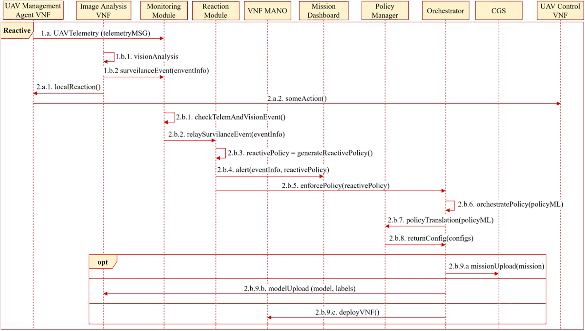
Figure 4: Reactive workflow
Once the monitoring module receives the data (Fig. 4-2.b.1), it verifies if there is any alert/issue. In that case (e.g., visual monitoring target was detected), it will ask the reaction module to generate a reaction that adapts the system according to the detection (Fig. 4-2.a.2). To do this, the reaction module will create a new policy that will include the actions required to adapt the system (Fig. 4-2.b.3), not only considering the information provided by the UAV but also the whole status of the infrastructure. The issue and autonomous countermeasure are notified to the user through the mission control panel (Fig. 4-2.b.4), whereas the countermeasure is sent to the orchestrator so that it can be automatically applied (Fig. 4-2.b.5). The orchestrator will orchestrate the reactive policy (Fig. 4-2.b.6) and requests to the policy manager the reactive policies translation in order to retrieve the specific configurations of the selected enforcement points (Fig. 4-2.b.7 and 8).
Some possible reactions that could be generated from the reaction module could be an update/modification in the route of UAVs according to knowledge about the status of the infrastructure (Fig. 4-2.b.9.a), an update/modification in the image analysis model to find more specific patterns according to precious detections, (Fig. 4-2.b.9.b), to deploy new sensing VNF to complement current detections (Fig. 4-2.b.9.c) or even sending a new/other UAVs to replace one in critical status (e.g., battery issues and therefore is returning home) or to complement current mission.
This section provides the implementation details of the solution to validate the provided design. Fig. 5 shows an overview of the implemented components, the technologies used, and their interactions. The implementation has focused mainly on the enforcement plane. A quadcopter UAV has been assembled and configured from scratch using open-source technologies such as iNav4, the software installed on the flight controller. The UAV has been equipped with a Raspberry Pi, which acts as a MEC node, able to run the VNFs implemented and to which a camera is connected, allowing image capturing. The MEC node is also connected to the flight controller and coupled to the UAV via printed parts using 3D printing technology. Regarding the implemented VNFs, the first one allows managing the UAV through a REST API that transforms orchestration plane requests into MAVLink control protocol messages, using the pyMavlink5 library offered by the protocol developers, and bypassing certain peculiarities of the iNav software, as it is intended for UAVs that maintain a direct and constant connection with a radio station that has been dispensed with for reasons that will be discussed later. The other VNF implemented provides image capturing and analysis, supported by the TensorFlow Lite machine learning library6. It also provides a REST API that allows uploading models, activating and deactivating the analysis process, and visualizing the status of the object detector.
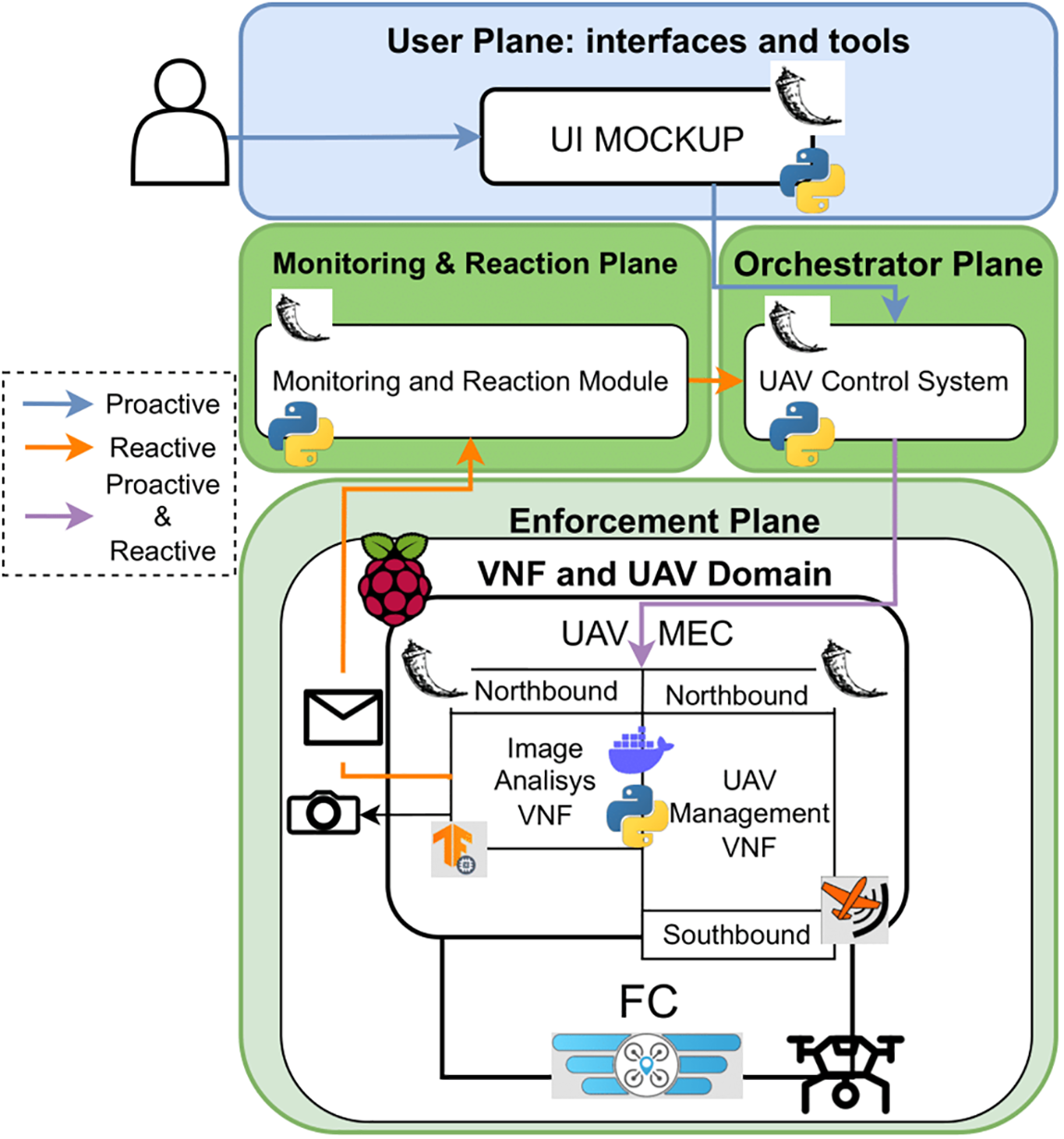
Figure 5: Implemented solution
In order to provide proactive and reactive workflow features as well as integration capabilities, the PoC implementation of some of the next-generation framework components has also been carried out for the rest of the planes, such as the UAVs control system belonging to the plane of orchestration that communicates with the control VNF installed on the mounted UAV, the reaction and monitoring module that generates a reaction and applies it through of the UAV control system when the implemented image analysis VNF performs the detection of an object and a prototype of the policy editor with which to create visual monitoring missions through the specification of the target pattern, the start and end times of the mission and the area or route that the UAV has to follow. The implementation details of each of these components are detailed below.
The first step was to choose a structure for the UAV or frame, which would allow us to load the necessary components, so we decided to use a frame with a 300mm wheelbase, which uses 7-inch propellers, which is long and large enough to house the Raspberry Pi that acts as a low consumption MEC node. Once the structure was chosen, the motorization and the propellers that drive it were chosen. The chosen engines were 2306 engines model, numbering that indicates the size of the engine, of 1950 Kv with a maximum thrust of 1.9 kg. However, the ideal would have been 1600Kv motors due to the chosen propellers’ characteristics, which have three blades 7 inches long and 3.5 inches pitch; they were impossible to obtain because the supplier did not have them available. The next step was to choose a speed controller (ESC) that could withstand the power required to move the motorization and admit batteries of 4 cells, so a 50 Amp controller based on BLHeli32 firmware was chosen, which supports batteries between 3 and 6 cells. As a battery, several 4-cell batteries compatible with the ESCs, with a capacity of 2300 mah, and a download rate of 45C, give us sufficient autonomy to carry out stable flight tests. The main characteristic required to choose the flight controller was to support the execution of control software that allows performing flight plans, so a flight controller capable of running iNav was chosen, powered by an STM32-F722SE processor of 216 MHz, two gyroscopes (PU6000 and ICM20602), BMP280 barometer, AT7456E OSD, a module for a micro SD card for black box function and 5 Universal Asynchronous Receiver-Transmitter (UART) ports for connecting different sensors and components such as the GPS for the positioning data and the Raspberry Pi itself that acts as a node MEC. We chose a Raspberry Pi model 4B with 8 GB of RAM, which has enough power to execute the proposed VNFs, even though it does not have hardware specialized in the execution of machine learning algorithms. A receptacle has been created using 3D printing technology to accommodate both GPS and the Raspberry Pi.
Fig. 6 shows a simplified connection diagram of the different components of the UAV and the onboard computer node. We did not include an First Person View (FPV) vision system since that kind of vision system is intended for manual flights, and this work aims to carry out autonomous flights. It is easier to access the images using the camera module from the Raspberry itself, and in addition, the system would suppose an expense and an extra weight. Nor has it been used usual radio receiver in assemblies intended for radio control because the goal is to get the UAV to fly autonomously. This last decision causes a problem since the control software constantly checks the radio connection with the station whose solution is described in the implementation of the control VNF. Finally, it should be noted that only one connection has been made between the Raspberry and the Flight Controller (FC) because after several experiments, it was not possible to make two connections work at the same time, so the controlling VNF of the UAV, as will be seen later, will have to be able to correctly manage the connection to receive the telemetry data and send orders so that the messages are not corrupted.
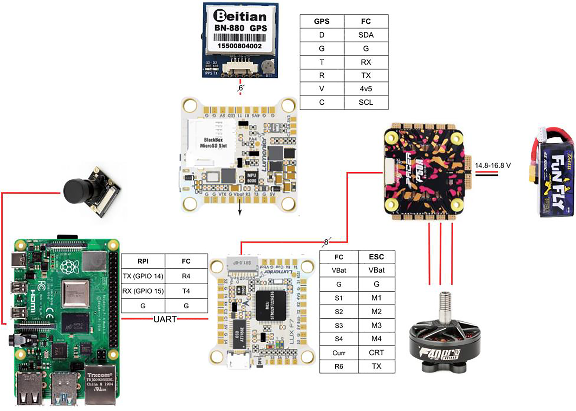
Figure 6: Simplified wiring
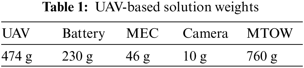
The total take-off weight of the whole UAV solution considering the components mentioned above (MTOW-Maximum Take-off Weight), as shown in Table 1, is 760 g, which is affordable for the engines used since each one provides a thrust of 1.9 Kg.
The final result of the assembly carried out is shown in Fig. 7, in which it can be seen how the MEC node has been attached to the 3D printed parts. The landing gear was also printed.
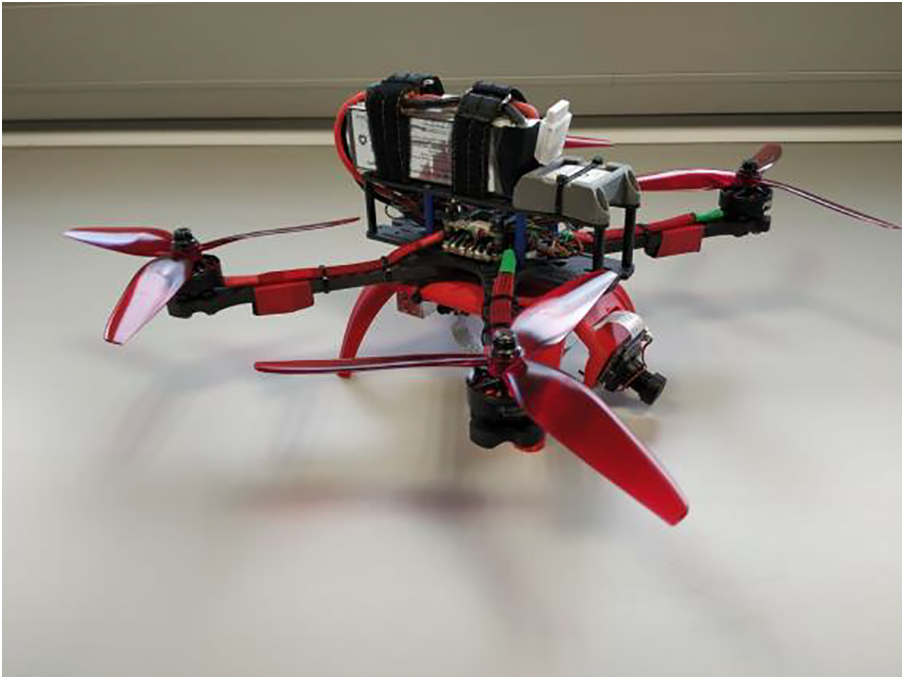
Figure 7: Assembled UAV-based security enabler
The software installed on the flight controller was iNav version 3.0.2. It was chosen because it is open-source software and allows flights to be carried out autonomously through flight plans and the control of the UAV through the MAVLink protocol. To configure the FC according to the wiring, we configured the USB port as Virtual Com Port (VCP), which indicates the USB connection used to configure the drone via the iNavConfigurator. The UART1 port was configured for GPS purposes, with a rate of 115200 bauds. The UART3 port was initially configured for FPV video transmission to carry out the flight tests manually, but that was finally not used since autonomous flights will be carried out. The images will come from the camera installed directly on the Raspberry Pi. The UART4 port was configured for providing communication and telemetry through MAVLink at 115200 bauds. This is the port to which the Raspberry Pi is connected, and the bidirectional communication is carried out. Lastly, the UART6 port was configured through which the connection of the telemetry between the FC and the ESC.
An 8 GB Raspberry Pi 4 has been chosen as the MEC node, where UAV control and image analysis VNFs are deployed. It has been chosen because the board provides multiple serial ports to interact with the FC, Wi-Fi to facilitate connectivity with the rest of the system (for testing purposes), easy camera integration, good price/performance/power consumption trade-off, and a great supporting community behind it. The connection to the FC uses the serial port UART0, as indicated in the connection diagram shown in Fig. 6. To provide communication between the UAV and the rest of the system during the tests, it has been connected to a Campus Wi-Fi access point. However, in the future, it will be connected through 5G (ongoing). Regarding the onboard dynamically deployed VNFs, they are detailed below.
Fig. 8 shows the UAV management VNF enforcement interfaces. This VNF implements a Northbound interface that allows communication between the UAV and the upper layers of the system. It also implements a Southbound interface that allows communication with the FC according to its specific technology, in this case, MAVLink. It should be noted that before arriving at the solution described below, it tried to use software such as mavproxy7 and dronekit8 for communication via MAVLink, as well as open-source MSP libraries, are written in Python to validate the communication. However, in the first case, it did not work correctly due to the limited implementation of MAVLink in iNav, so it was only possible to extract telemetry but not send messages. In the second case, it was impossible to obtain interaction due to a lack of documentation of the libraries and the protocol.
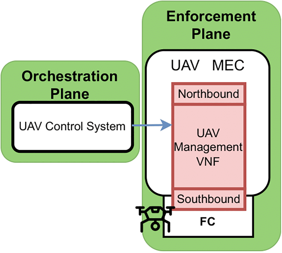
Figure 8: UAV Management VNF enforcement interfaces
The Northbound interface favors the interoperability of the UAV control system, allowing managing the UAVs through this interface that harmonies communication and abstracts it from the underlying control technology of each vehicle. It implements a REST HTTP API made with the Python 3 framework, Flask (version 2.0.1). The following endpoints have been implemented: (i) POST action to startMissionModule endpoint starts the UAV handling module and the connectivity with the FC through the southbound interface. It returns a JSON-encoded message indicating whether the mission started successfully or not. (ii) POST action to stopMissionModule to stop the UAV handling module. It is responsible for stopping the communication with the FC and returns a JSON-encoded message indicating whether the module stopped successfully. (iii) The method to arm the UAV is executed through a request with the method POST to the arm URL path, which arms the UAV through the southbound interface and returns a JSON-encoded message indicating whether the operation was successful. (iv) The method to disarm the UAV is executed through a request with the method POST to the disarm URL path, which allows disarming the UAV through the southbound interface and returns a JSON-encoded message indicating whether the operation was executed with success. (v) The method to check if the UAV is armed is executed through a request with the GET method to the isArm URL path, which allows knowing the current state of the UAV and returns a JSON-encoded message indicating whether the UAV is armed or not. (vi) Deleting the mission from the FC is executed through a request with the POST method to the cleanMission URL path. It allows the deletion of the mission loaded in the FC and returns a JSON-encoded message indicating whether the operation was executed successfully. (vii) The method to upload a mission to the FC is executed through the URL uploadMission path, and its behavior varies depending on the HTTP method you call it with. Whether using the POST method without parameters, a mission with five points will be created and uploaded (for testing purposes). If called with the numwp parameter, a mission will be created and uploaded with the number of waypoints indicated in said parameter. These two calls were implemented to check how iNav handled this type of MAVLink messages and perform mission load tests without depending on a file indicating the route. Calls with the POST method must include a file of the mission encoded in Extensible Markup Language (XML), which is analyzed, giving rise to the mission that is finally uploaded to the controller through the southbound interface. The answer to all these calls is a JSON-encoded message indicating whether the operation was carried out successfully.
Regarding the Southbound API, it is responsible for offering control of the assembled UAV allowing communication between the Raspberry Pi and the FC through the physical link of the UART port, adapting the requests made to the Northbound interface to the protocol messages MAVLink, using the PyMavlink library (version 2.4) offered by the developers of this protocol. It was required to resort to the documentation of the protocol, the examples included in the iNav library, and documentation and source code, as this flight software does not fully implement the MAVLink protocol, so it has been necessary to adapt the indications given by the developers of the protocol with the current implementation flight software does. To communicate between the node MEC and FC, the following classes and methods were implemented: (i) The RCChannelsValues class stores the status of the 16 radio channels that both MAVLink and the FC handle. The value of each of these channels goes from 1000 to 2000. It represents the position of the various controls, such as the position of the switches that allow activating or deactivating features shown in the iNav settings. (ii) The Mymavlink class implements the methods that allow the control of the UAV using the MAVLink protocol. It is composed of two threads that execute an infinite loop to send messages to the controller with the status of the RC channels to prevent the UAV from entering the FailSafe state, one of the peculiarities of iNav, and the reception of telemetry in addition to the methods that implement the rest of functionality, such as uploading missions. Since there is only one connection and all messages use that connection, it has been necessary to use a lock to manage access to prevent them from being corrupted. The attributes that characterize the class are the module state, which sets the state of the interface and thus finalizes the infinite loop of the threads; the radio channel status, which stores the current value of the radio channels; the sending frequency that configures the sending frequency of the radio channels sent to the FC; the telemetry reception frequency that configures the reception frequency of telemetry messages sent by the FC; baud rate of the connection to configure the baud rate of the connection with the FC; connection port to configure the port of the Raspberry that is used in the UART connection with the FC, and finally MAVLink connection protection lock that protects the MAVLink connection.
Regarding the implemented methods, (i) Constructor allows you to build an instance of the class and set the port in which the physical connection is made and the baud rate. (ii) ModuleStart sets the module state to active, creates the MAVLink connection, sets the initial value of the radio channels, and initiates the connections for receiving telemetry and sending the radio channels. (iii) ModuleStop stops the telemetry receiving connections, and the sending of the radio channels closes the connection and establishes the state of the module as stopped. (iv) MAVLink connection establishment, used in the method module startup, creates the MAVLink connection on the port and with the baud indicated through the constructor. After this, it waits for a MAVLink message of type heartbeat that guarantees the connection has been made successfully following the protocol specification. (v) Set the initial state of the radio channels. iNav requires a consistent initial value in the channels referring to position control of the UAV as in the channels that establish the operating mode of the firmware. These values can range from 1000 to 2000 and are set based on the configuration made in iNav. Therefore, through this method, used in the module start method, it is possible to set the value of the control channels of yaw, roll, and pitch to 1500, the throttle value to 1000, and the throttle value to the arming switch to 1000. (vi) Arm method allows arming the UAV by setting the value of the arming channel radio dedicated to it, in this case, 2000. (vii) Disarm method allows disarming the UAV by setting the value of the radio channel dedicated to it, in this case, 1000. (viii) Mission load method allows loading a mission in the FC. Its behavior varies depending on the parameters with which it is invoked. In particular, it will create a mission composed of as many waypoints as indicated. (ix) Checking the arming switch method allows knowing if the UAV is armed by checking the current value of the radio channel. Given the configuration made in the firmware, if it has a value of 2000, it is considered that the UAV is armed.
Since the solution can be easily integrated with security frameworks, different security VNFs can be deployed as part of proactive/reactive countermeasures. For instance, traffic monitoring tools, custom access points, or more advanced visual monitoring tools could be deployed and configured dynamically. In this case, we deployed an ML-based VNF to detect and classify objects, triggering an alert once the detection occurs since this is an expected behavior needed in UAV scenarios like Search and Rescue missions. The sensorization VNF implemented in this work provides image analysis using artificial intelligence algorithms. This VNF is intended for detecting objects in the images captured by the camera installed on the Raspberry Pi. Fig. 9 shows the AI-based monitoring VNF enforcement interfaces. The Northbound interface, a REST API, exposes methods for managing the VNF, including a Python module that executes the object detection process by relying on TensorFlowLite object detection features9, library version 2.8.
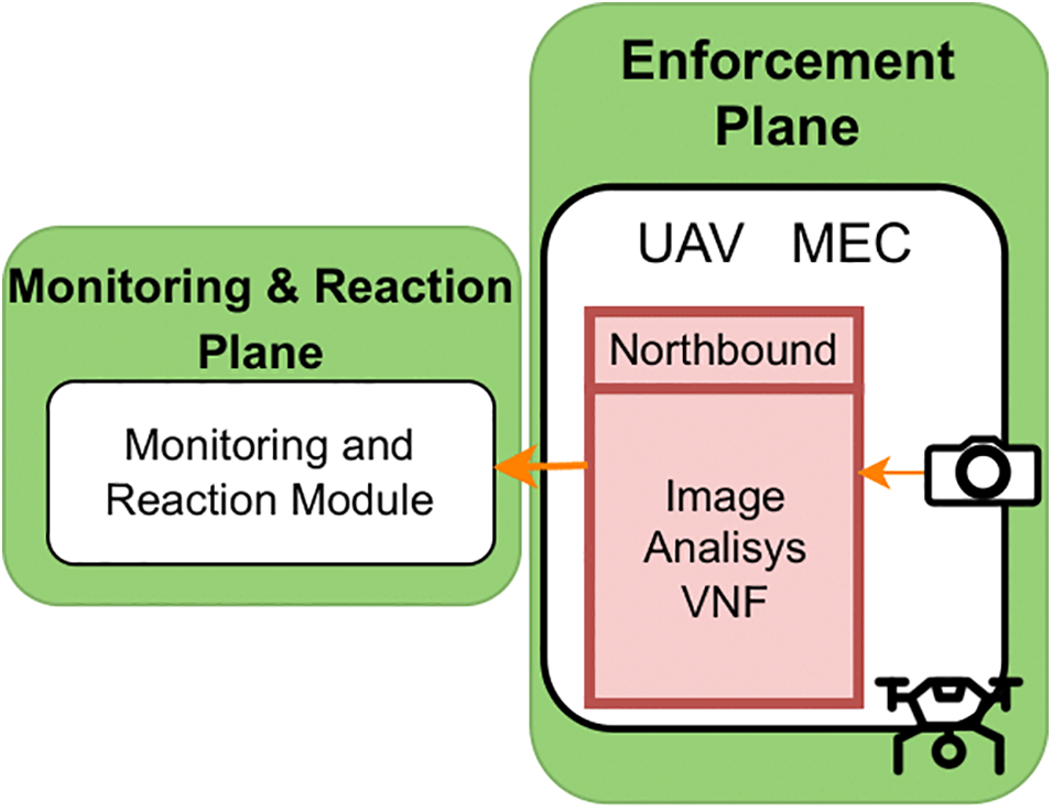
Figure 9: UAV AI-based monitoring VNF interfaces
To allow the orchestration plane to manage the vision VNF, a REST API using the Python 3 Flask framework (version 2.1) has been implemented. The implemented methods are; (i) The method to start the image analysis module, executed through a request with the POST method to the startVisionModule URL path. (ii) The method to stop the image analysis module is executed through a request with the POST method to the stopVisionModule URL path. (iii) The method to upload a model is executed through a request with the POST method that includes the model file to the uploaderModel URL path. (iv) The method to start an HTTP server for relaying the images captured and analyzed is executed through a request with the method POST to the URL startStreamingServer path. Lastly, (v) the method to stop the HTTP server from relaying the images is executed through a request with the POST method to the URL stopStreamingServer path.
The image analysis module has been implemented in Python, creating an image processing library that relies on TensorFlowLite version 2.8, a machine learning library intended for devices with few resources, which performs the classification of images captured by the Raspberry Pi camera. An HTTP image server is also provided to visualize the analysis performed in real time. Following, the classes and modules implemented are showcased. The ImageProcessor class executes the loop in which the camera captures the images connected to the Raspberry Pi and calls the image analyzer to make the classification. The attributes that characterize it are (i) The width of the captured image, which must be consistent according to the model, which has been trained for a specific image size. (ii) Height of the captured image, like the previous attribute, must be in accordance with the model. (iii) Image capture rate allows you to modify the image capture rate. Its default value is 30 images per second. (iv) Maximum Object Detector Results allows you to set the maximum number of detections made by the detector. (v) The prediction limit allows you to set the minimum score for a prediction to be considered valid. (vi) Model file path stores the path to the model file to be used by the object detector. (vii) Number of threads allows you to configure the number of threads that the detector will use during the detection process.
The developed methods are explained following; (i) Constructor: A constructor without parameters and another constructor which indicates the retransmission server’s port and the model file’s path. (ii) Start image processing allows you to start the thread that captures and processes the images. (iii) Stop image processing allows you to stop pictures’ capture and processing thread. (iv) Check Image Processor Status allows you to check if the image processor is running or stopped. (v) Start HTTP Relay Server allows you to start the thread that creates an HTTP server to relay the images. (vi) Stop HTTP Relay Server allows stopping the thread in which the HTTP server executes it for relaying the images. (vii) Check Relay Server Status functionality lets you check if the thread running the relay HTTP server is active. (viii) Load model allows you to change the analysis model of the object detector. (ix) Tensorflow processor executes the capture and processing of images. To this aim, it creates the object detector according to the abovementioned parameters. Then it starts a loop in which the PiCamera library captures the images while the thread is active. The following process is performed for each of the captured images. The image is converted into an array with the asarray method of the NumPy library. The array is encoded using the imdecode method of the OpenCV10 library. The result is analyzed by the object detector, which will return an array that includes, for each detection, the prediction made, the confidence value of the prediction, and the position of this within the image. Then the image is annotated with the analysis results using the ObjectDetector module’s visual method, which relies on OpenCV’s putText method. If the relay web server is active, the annotated image is saved in an output buffer that can be consumed through the server. The predictions are extracted from the results and compared to the search target. If it matches, a call is made to the REST API of the monitoring and reaction module, in which the image is sent, encoded in base64, and the results of the analysis. Finally, the input buffer is reset to be ready for the following catch.
The ObjectDetector module comes from the examples provided by the library TensorFlowLite for low-resource devices like the Raspberry Pi. It is composed of the following classes: (i) ObjectDetectorOptions class: This class contains the configuration options of the object detector, such as the existence of a TPU hardware calculation module, a list of categories to be taken into account, a list of categories not to be taken into account count, the maximum number of results, number of threads to use and score limit to consider a valid prediction. (ii) Rect class: This class represents the rectangle with which an object is delimited that has been detected. (iii) Category class: This class represents the result of the detection performed, and its attributes are the category, the score obtained, and an index. (iv) Detection class: This class represents the detection carried out and comprises a rectangle and a list of categories. (v) ObjectDetector class: This class is the detector itself, and it provides the constructor, which receives as parameters the route of the model and configuration options.
To validate the design and implementation of the solution, focused on the enforcement plane of the designed architecture, the loading time of the missions in the UAV was measured since it is an essential element of the proactive flow, as well as the AI-based detection and reaction times. The main reason to focus on these measurements is that as a dynamic security enabler, it is important that the new solution can be dynamically deployed and reconfigured as fast as possible in both proactive and reactive stages. Otherwise, the scenarios in which the solution could be considered a reactive countermeasure would be reduced. To validate mission loading tasks, we enforced missions of different sizes in the FC through the UAV control VNF making calls to the Northbound REST API of the UAV control VNF, which allows loading a mission with as many waypoints as those indicated in the configuration parameters. The waypoints used in the tests range from 1 to 60 waypoints as it is the maximum allowed by iNav implementation. Waypoints with an identifier above this number are reserved for special iNav functions. Fig. 10 shows the results for mission loading. As can be seen, the loading time increases as the number of waypoints increases since iNav processes them sequentially. The more complex the mission, the longer it takes. The time for enforcing a mission with one waypoint takes around 318 milliseconds, whereas it takes to apply configurations for 60 waypoints is around 6.2 s. The observed variability in mission enforcement times between results for the same number of waypoints is due to two reasons. On the one hand, the use of locks in the implemented code, since we used only one physical connection for sending commands and receiving telemetry from the FC due to iNav and FC technical limitations (it was not possible to use two connections in the current deployment). On the other hand, iNav has a real-time task manager based on priorities in which the task of checking port data serial has a low priority. Based on the results, the time required to enforce a mission plan in the FC through the UAV control VNF will depend on the mission’s complexity. However, regular missions are usually composed of less than 30 waypoints, so the time the enforcement of the mission plan takes is below3 s. Besides, it is essential to highlight that the FC enforcement consumes 86.11% of the time, whereas the VNF consumes the rest to manage the request received from the northbound API and transform it to MAVLINK requests through the southbound API.
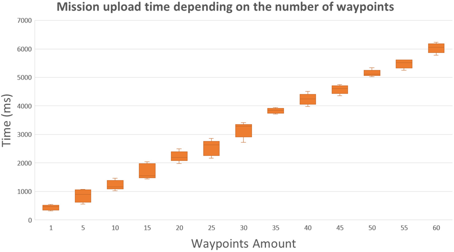
Figure 10: Mission upload performance
To validate the reactive workflow, we consider the detection and reaction times at the enforcement plane to calculate the time the solution needs to be dynamically reconfigured. Specifically, we measured the time taken by the visual monitoring VNF to detect the required target and the time taken since the detection occurs until the control VNF of the UAV applies an autonomous UAV reaction. To measure the detection performance, we placed different objects in the range of vision of the onboard camera, and we started the image analysis process by using the VNF northbound, registering the average time required to perform the analysis and notifying the detection to the monitoring module PoC by sending an alert according to the desired target. The model relies on the TensorFlowLite library, being a single-shot detection model, and we use 300x300 pixel images captured by the RPi camera as input data. Since the UAV compute node could execute different security VNFs simultaneously for different purposes, we measured the performance considering different threads’ quantity. Fig. 11 shows the results that measure the impact of the number of threads used in the image analysis by varying this parameter from 1 to 6 threads. The results show that the system works better using four threads, taking around 152 milliseconds. Below this threat amount, the software does not explode all the available cores (4 in the Raspberry Pi model we use). Above this threat amount, the results worsen considerably due to the exceeding threats overloading the system.
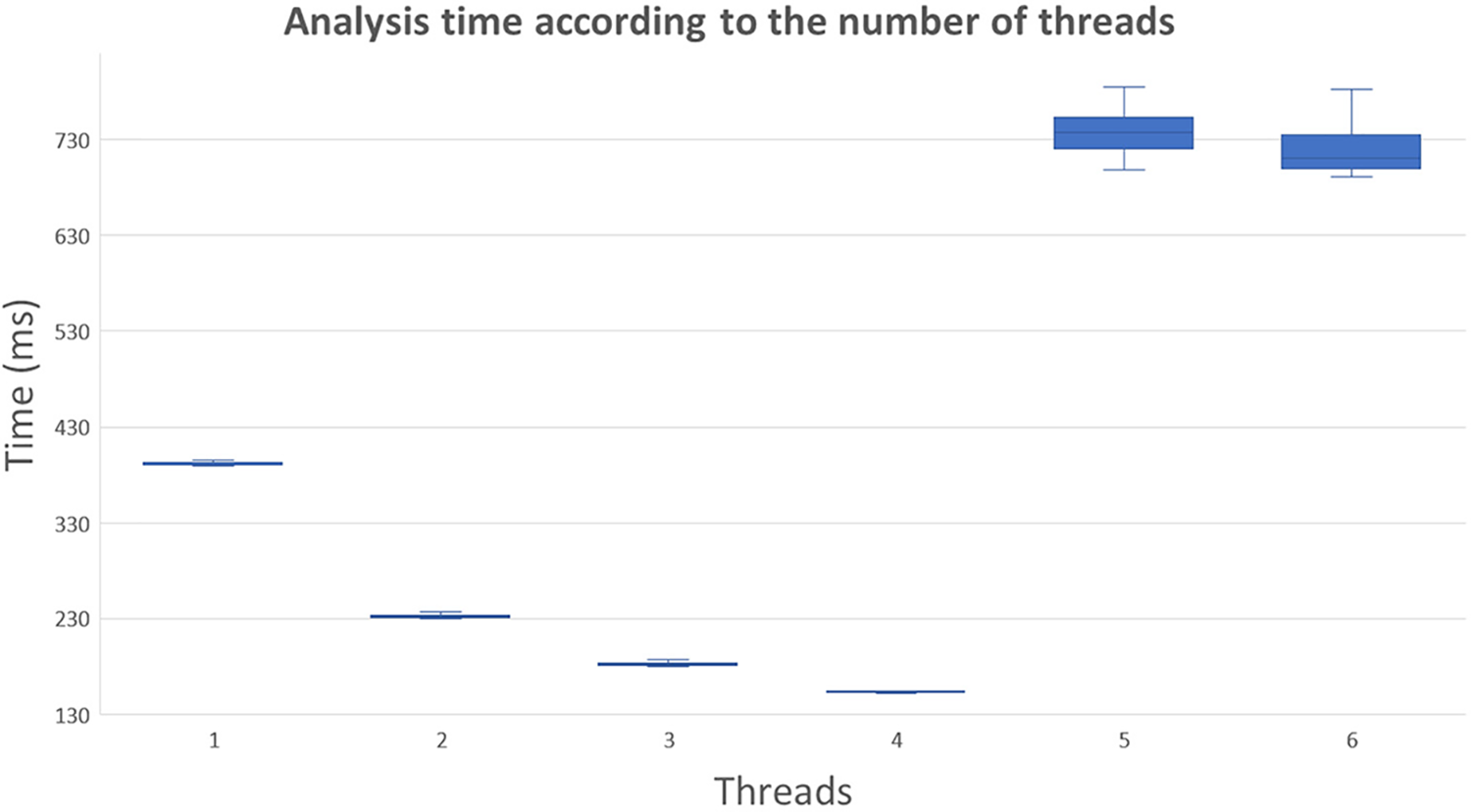
Figure 11: AI-based detection performance for different CPU threads
Apart from the time required to analyze and detect single objects, we also analyzed the impact of detecting multiple objects simultaneously. Fig. 12 shows the results of repeating the previous experiment but, in this case, putting a different number of detectable objects on the onboard camera range. For this experiment, we used three threads, as we reserved one for the UAV control VNF. As expected, the results show an increasing trend, taking around 183 milliseconds to detect two objects and around 215 milliseconds to detect three objects.
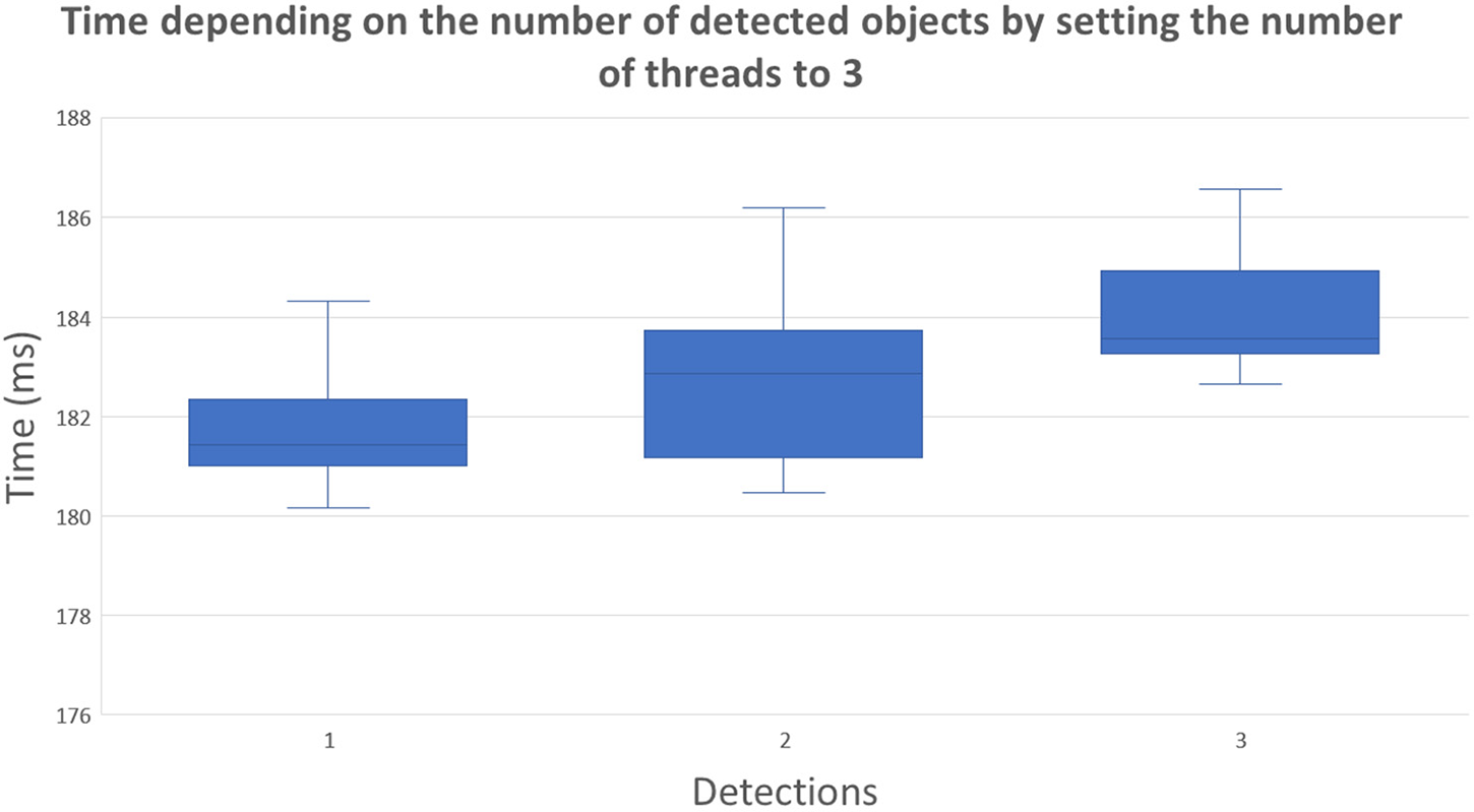
Figure 12: AI-based detection performance depending on objects number
Finally, we measured the elapsed time to measure the reaction time since the image analysis VNF detects the requested target until the UAV control VNF enforces a new autonomous behavior received from the UAV control system PoC. As part of the experiment in the lab, we predefined the disarming of the UAV as a primary reaction. However, other basic behaviors, such as returning home and landing, can be enforced. More advanced behaviors could be dynamically computed and provided by reaction modules of next-generation frameworks, for instance, new adaptative and complex mission plans that also involve new deployments and reconfigurations of security VNFs according to the detected issue. Fig. 13 shows the reactive enforcement experiments to get the average time the UAV control VNF takes to command a new basic behavior. The results range from 0.97 to 1.35 s, providing an average time of 1.09 s. As it also happens in the proactive stage, the deviation is due to the internal locks and how iNav manages the internal loop and signals. Considering the detection time, the proposed solution can detect and enforce basic physical UAV reactions in less than 1.5 s.
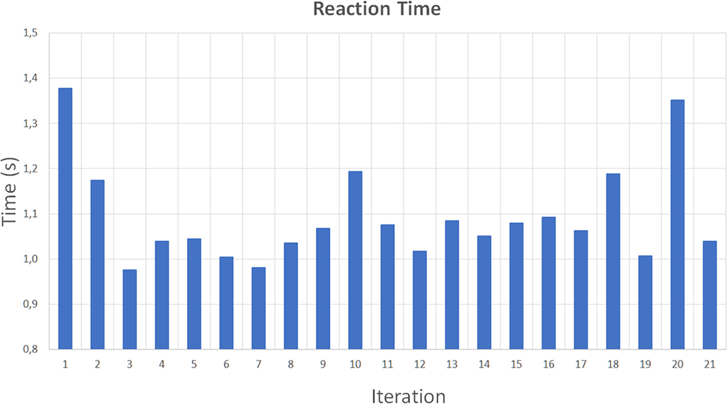
Figure 13: Reaction performance
According to the results, the solution can apply proactive visual 3 s, detect patterns, and apply UAV-related actions in around 1 s. The results align with previous results for other security enablers, such as dynamic filtering and IoT enforcement [1,2]. Notice that since our implementation focused on the enforcement plane, we focused on the time required to enforce the configurations in the UAV, so the VNF deployment time was not considered. Different studies, such as [17,20], show that a VM-based approach takes around 40 s to deploy a single VNF in a constraint device, so the measures/countermeasures would be increased in that time in case the VNF was not previously deployed. However, depending on the distance the UAV is from the mission location, flying to the destination could take longer than the instantiation and enforcement time.
This paper has provided a UAV-based MEC solution able to be integrated with next-generation frameworks such as Anastacia-H2020 or INSPIRE-5GPlus as a security enabler. To this aim, we design and provide workflows to facilitate solution integration and proactive and reactive functionality approaches. To validate the solution, whereas the design and workflows cover the whole vertical, the implementation effort focused on the architecture enforcement plane. Specifically, we assembled the UAV from scratch, using as much open-source software/hardware as possible, and we provided detailed assembly information in this regard. Then we implemented the designed UAV management VNF that allows the command of different kinds of UAVs with onboard MEC nodes by using them as policies enforcement points. The implementation followed a modular approach, providing northbound and southbound interfaces for abstracting the underlying technologies to the upper layers of the framework, as well as for allowing on-demand deployments and configurations that modify the automated UAV behavior. As an example of MEC node security VNF, an ML-based VNF able to perform image object detection and reactions based on TensorFlow was also implemented to validate the reaction stage. This VNFs implementation followed the same modular approach to modify the detector behavior and the required local reaction on demand. Finally, we validated the solution by enforcing different UAV and ML-based VNFs configurations and triggering the reaction part by putting an object suitable for the ML model in the camera range. Thus, when an object was detected, the configured reaction was triggered, which in the current implementation, we trigger a modification of the UAV behavior through the UAV management VNF. The results showed that the proactive stage, considering ten waypoints in the flying plan, is performed in less than 3 s, and a basic reactive flow can be achieved in around 1 s for basic UAV commands (e.g., landing, disarm). As discussed in the performance evaluation section, the results will depend on the complexity of the required behavior (e.g., the number of waypoints). However, we consider that the results and possibilities are promising, and they are aligned with other security enabler solutions as part of existing 5G/6G security frameworks.
In future work, some aspects of the current implementation and results could be enhanced using different hardware for specific purposes. AI-dedicated hardware could also be included as part of the MEC solution to improve the results of the AI-based VNFs. Local reactions could be generated dynamically instead of being predefined. Multiple communication channels and technologies should be provided. In our case, 5G is ongoing. We recommend using other kinds of FC software since we have several issues automating the iNav behavior since it does not fully implement MAVLINK. Besides, it is expected to extend the solution to be part of UAV fleets, focusing on the user interface and UAV controller at the control and user planes, respectively.
Acknowledgement: This paper and the research behind it would not have been possible without the financial support of the ONOFRE-3 and CERBERUS projects and the Department of Information and Communications Engineering (DIIC) of the University of Murcia.
Funding Statement: The research is supported by the ONOFRE-3 project, Grant Agreement PID2020-112675RB-C44, funded by MCIN/AEI/10.13039/501100011033. The study also received funds from the Spanish Ministry of Economic Affairs and Digital Transformation and the European Union – nextGeneration EU [TSI-063000-2021-36, TSI-063000-2021-44, TSI-063000-2021-45, TSI-063000-2021-62]. Antonio Skármeta received them.
Conflicts of Interest: The authors declare that they have no conflicts of interest to report regarding the present study.
1https://www.etsi.org/technologies/zero-touch-network-service-management
3https://www.hamishmb.com/multiwii/wiki/index.php?title=Multiwii$delimiter"026E30F$_Serial$delimiter"026E30F$_Protocol
4https://github.com/iNavFlight/inav
5https://pypi.org/project/pymavlink/
6https://www.tensorflow.org/?hl=es-419
7https://ardupilot.org/mavproxy/
9https://www.tensorflow.org/lite/examples/object_detection
References
1. A. M. Zarca, J. B. Bernabe, R. Trapero, D. Rivera, J. Villalobos et al., “Security management architecture for NFV/SDN-aware IoT systems,” IEEE Internet of Things Journal, vol. 6, no. 5, pp. 8005–8020, 2019. [Google Scholar]
2. P. Alemany, A. Molina, C. Dangerville, R. Asensio, D. Ayed et al., “Management and enforcement of secured E2E network slices across transport domains,” Optical Fiber Technology, vol. 73, no. 4, pp. 103010, 2022. [Google Scholar]
3. J. Sun, B. Li, Y. Jiang and C. Wen, “A camera-based target detection and positioning UAV system for search and rescue (SAR) purposes,” Sensors, vol. 16, no. 11, pp. 1778, 2016. [Google Scholar] [PubMed]
4. J. Scherer, B. Rinner, S. Yahyanejad, S. Hayat, E. Yanmaz et al., “An autonomous multi-UAV system for search and rescue,” in Proc. First Workshop on Micro Aerial Vehicle Networks, Systems, and Applications for Civilian Use, Florence, Italy, pp. 33–38, 2015. [Google Scholar]
5. K. Whitehead and C. H. Hugenholtz, “Remote sensing of the environment with small unmanned aircraft systems (UASspart 1: A review of progress and challenges,” Journal of Unmanned Vehicle Systems,vol. 2, no. 3, pp. 69–85, 2014. [Google Scholar]
6. E. Tuyishimire, A. Bagula, S. Rekhis and N. Boudriga, “Cooperative data muling from ground sensors to base stations using UAVs,” IEEE Symposium on Computers and Communications (ISCC), vol. 54, pp. 35–41, 2017. [Google Scholar]
7. P. Liu, A. Y. Chen, Y. N. Huang, J. Y. Han, J. S. Lai et al., “A review of rotorcraft unmanned aerial vehicle (UAV) developments and applications in civil engineering,” Smart Structures and Systems, vol. 13, no. 6, pp. 1065–1094, 2014. [Google Scholar]
8. C. Deng, S. Wang, Z. Huang, Z. Tan and J. Liu, “Unmanned aerial vehicles for power line inspection: A cooperative way in platforms and communications,” Journal of Communications, vol. 9, no. 9, pp. 687–692, 2014. [Google Scholar]
9. H. Shakhatreh, A. H. Sawalmeh, A. Al-Fuqaha, Z. Dou, E. Almaita et al., “Unmanned aerial vehicles (UAVsA survey on civil applications and key research challenges,” IEEE Access, vol. 7, pp. 48572–48634, 2019. [Google Scholar]
10. Y. Huang, S. J. Thomson, W. C. Hoffmann, Y. Lan and B. K. Fritz, “Development and prospect of unmanned aerial vehicle technologies for agricultural production management,” International Journal of Agricultural and Biological Engineering, vol. 6, no. 3, pp. 1–10, 2013. [Google Scholar]
11. V. Gonzalez-Dugo, P. Zarco-Tejada, E. Nicolás, P. A. Nortes, J. J. Alarcón et al., “Using high resolution UAV thermal imagery to assess the variability in the water status of five fruit tree species within a commercial orchard,” Precision Agriculture, vol. 14, no. 6, pp. 660–678, 2013. [Google Scholar]
12. R. Ke, Z. Li, S. Kim, J. Ash, Z. Cui et al., “Real-time bidirectional traffic flow parameter estimation from aerial videos,” IEEE Transactions on Intelligent Transportation Systems, vol. 18, no. 4, pp. 890–901, 2016. [Google Scholar]
13. J. Leitloff, D. Rosenbaum, F. Kurz, O. Meynberg and P. Reinartz, “An operational system for estimating road traffic information from aerial images,” Remote Sensing, vol. 6, no. 11, pp. 11315–11341, 2014. [Google Scholar]
14. H. Fatemidokht, M. K. Rafsanjani, B. B. Gupta and C. H. Hsu, “Efficient and secure routing protocol based on artificial intelligence algorithms with UAV-assisted for vehicular ad hoc networks in intelligent transportation systems,” IEEE Transactions on Intelligent Transportation Systems, vol. 22, no. 7, pp. 4757–4769, 2021. [Google Scholar]
15. A. Wada, T. Yamashita, M. Maruyama, T. Arai, H. Adachi et al., “A surveillance system using small unmanned aerial vehicle (UAV) related technologies,” NEC Technical Journal, vol. 8, no. 1, pp. 68–72, 2015. [Google Scholar]
16. R. L. Finn and D. Wright, “Unmanned aircraft systems: Surveillance, ethics and privacy in civil applications,” Computer Law & Security Review, vol. 28, no. 2, pp. 184–194, 2012. [Google Scholar]
17. B. Nogales, V. Sanchez-Aguero, I. Vidal and F. Valera, “A NFV system to support configurable and automated multi-UAV service deployments,” in Proc. 4th ACM Workshop on Micro Aerial Vehicle Networks, Systems, and Applications, Munich Germany, pp. 39–44, 2018. [Google Scholar]
18. B. Nogales, V. Sanchez-Aguero, I. Vidal and F. Valera, “Adaptable and automated small UAV deployments via virtualization,” Sensors, vol. 18, no. 12, pp. 4116, 2018. [Google Scholar] [PubMed]
19. O. Bekkouche, M. Bagaaa and T. Taleb, “Toward a UTM-based service orchestration for UAVs in MEC-NFV environment,” in IEEE Global Communications Conf. (GLOBECOM), Piscataway, IEEE, pp. 1–6, 2019. [Google Scholar]
20. A. Hermosilla, A. M. Zarca, J. B. Bernabe, J. Ortiz and A. Skarmeta, “Security orchestration and enforcement in NFV/SDN-aware UAV deployments,” IEEE Access, vol. 8, pp. 131779–131795, 2020. [Google Scholar]
21. J. Gallego-Madrid, A. Molina-Zarca, R. Sanchez-Iborra, J. Bernal-Bernabe, J. Santa et al., “Enhancing extensive and remote LoRa deployments through MEC-powered drone gateways,” Sensors, vol. 20, no. 15, pp. 4109, 2020. [Google Scholar] [PubMed]
22. Y. H. Xu, J. H. Li, W. Zhou and C. Chen, “Learning-empowered resource allocation for air slicing in UAV-assisted cellular V2X communications,” IEEE Systems Journal, vol. 17, no. 1, pp. 1008–1011, 2023. [Google Scholar]
23. Y. H. Xu, X. Liu, W. Zhou and G. Yu, “Generative adversarial LSTM networks learning for resource allocation in UAV-served M2M communications,” IEEE Wireless Communications Letters, vol. 10, no. 7, pp. 1601–1605, 2021. [Google Scholar]
24. Y. H. Xu, Q. M. Sun, W. Zhou and G. Yu, “Resource allocation for UAV-aided energy harvesting-powered D2D communications: A reinforcement learning-based scheme,” Ad Hoc Networks, vol. 136, no. 3, pp. 102973, 2022. [Google Scholar]
25. Y. H. Xu, W. Zhou, Y. G. Zhang and G. Yu, “Stochastic game for resource management in cellular zero-touch deterministic industrial M2M networks,” IEEE Wireless Communications Letters, vol. 11, no. 12, pp. 2635–2639, 2022. [Google Scholar]
26. A. Omidkar, A. Khalili, H. H. Nguyen and H. Shafiei, “Reinforcement-learning-based resource allocation for energy-harvesting-aided D2D communications in IoT networks,” IEEE Internet of Things Journal,vol. 9, no. 17, pp. 16521–16531, 2022. [Google Scholar]
27. A. Molina-Zarca, J. Bernal-Bernabe, I. Farris, Y. Khettab, T. Taleb et al., “Enhancing IoT security through network softwarization and virtual security appliances,” International Journal of Network Management, vol. 28, no. 5, pp. e2038, 2018. [Google Scholar]
28. S. He, F. Bastani, A. Balasingam, K. Gopalakrishna, Z. Jiang et al., “Beecluster: Drone orchestration via predictive optimization,” in Proc. 18th Int. Conf. on Mobile Systems, Applications, and Services, Toronto, Ontario, Canada, pp. 299–311, 2020. [Google Scholar]
29. A. Koubâa, A. Allouch, M. Alajlan, Y. Javed, A. Belghith et al., “Micro air vehicle link (MAVlink) in a nutshell: A survey,” IEEE Access, vol. 7, pp. 87658–87680, 2019. [Google Scholar]
30. C. Qu, R. Singh, A. Esquivel-Morel and P. Calyam, “Learning-based multi-drone network edge orchestration for video analytics,” in Proc. IEEE INFOCOM 2022-IEEE Conf. on Computer Communications, Virtual Conference, pp. 1219–1228, 2022. [Google Scholar]
31. P. Gonzalez-Gil, A. Robles-Enciso, J. A. Martínez and A. F. Skarmeta, “Architecture for orchestrating dynamic DNN-powered image processing tasks in edge and cloud devices,” IEEE Access, vol. 9, pp. 107137–107148, 2021. [Google Scholar]
Cite This Article
 Copyright © 2023 The Author(s). Published by Tech Science Press.
This work is licensed under a Creative Commons Attribution 4.0 International License , which permits unrestricted use, distribution, and reproduction in any medium, provided the original work is properly cited.
 Downloads
 Citation Tools