
 Submit a Paper
 Propose a Special lssue
 Open Access
ARTICLE

Simulation of Offshore Wind Turbine Blade Docking Based on the Stewart Platform
College of Ocean Science and Engineering, Shanghai Maritime University, Shanghai, 201306, China
* Corresponding Author: Yi Zhang. Email:
Energy Engineering 2023, 120(11), 2489-2502. https://doi.org/10.32604/ee.2023.029496
Received 22 February 2023; Accepted 10 April 2023; Issue published 31 October 2023
 View Full Text
 Download PDF
Abstract
The windy environment is the main cause affecting the efficiency of offshore wind turbine installation. In order to improve the stability and efficiency of single-blade installation of offshore wind turbines under high wind speed conditions, the Stewart platform is used as an auxiliary tool to help dock the wind turbine blade in this paper. In order to verify the effectiveness of the Stewart platform for blade docking, a blade docking simulation system consisting of the Stewart platform, wind turbine blade, and wind load calculation module was built based on Simulink/Simscape Multibody. At the same time, the PID algorithm is used to control the Stewart platform so that the blade can effectively track the desired trajectory during the docking process to ensure the successful docking of the blade. Through the simulation of the docking process for blades with a length of 61.5 meters, this paper successfully demonstrates a docking system that might facilitate future docking processes. It also shows that the Stewart platform can effectively reduce the vibration and the movement range of the blade root and improve the stability and efficiency of blade docking.Keywords
In order to reduce carbon emissions, clean energy, including wind energy, has attracted wide attention. At present, the development of onshore wind power in China has become saturated. Offshore wind power has become a major development direction. This is because offshore wind power has significant advantages, such as not occupying arable land resources, stable wind power supply, and abundant wind energy resources [1]. Meanwhile, offshore wind power continues to develop from just off the coast to the far-reaching sea. However, the harsh marine environment makes the cost of blade installation account for 15%~20% of the total construction cost [2], which seriously restricts the construction and development of offshore wind power. At present, the blade is installed through a number of different methods such as full rotor lifting, rabbit ear lifting, and single blade lifting, in which the single blade installation can greatly improve the transportation efficiency of the installation ship and reduce the requirements for lifting equipment, significantly reducing the total installation cost [3].
At present, single-blade installation is the most widely used method. Single-blade installation first involves installing the nacelle and hub in place, then lifting the blades from the deck of the installation ship to the docking height, and next positioning the blade root close to the hub by crane. After careful adjustment, the blade root bolts are placed into the hub bolt hole for fixing. The above process is only controlled by two wind ropes to help reduce blade oscillation, which is often insufficient for stable lifting and accurate docking of the blades, resulting in a slow installation process and damage to the blade and increasing the total cost of construction [4]. With the ongoing trend of installing larger and larger blades, installation difficulty will also increase significantly.
In order to cope with the above engineering problems, the researchers carried out research on blade wind load calculation, blade motion control, and construction equipment to improve the installation stability. Kuijken [5] established a multi-body dynamic model including blades, wind ropes, and yoke and analyzed the dynamic characteristics of blades under different wind conditions. Zhao et al. [6] developed a simulation tool to analyze the motion of the blade. In order to reduce the oscillation problem caused by wind load during the blade lifting process, Ren et al. [7] established a three-degree-of-freedom hoisting model, which combined the Kalman Filter and PID to control the sling and wind rope, effectively reducing the blade vibration under a high wind load and improving blade installation efficiency. At the same time, he used a motion estimation algorithm to predict the motion of the hub, thereby reducing the relative motion of the blade root to the hub [8]. Guo et al. [9] adopted the unscented Kalman Filter to reduce the noise in the lifting process of a single blade, further improving the stability of the blade in the lifting process. However, the above research only theoretically analyzed the blade movement under the control of wind rope without considering the problem of implementation, so it has low feasibility.
A numerical study [10] showed that the hub motion caused by wind and waves seriously affects the safety of blade docking. Verma et al. [11–13] analyzed the blade root damage caused by hub motion. At the same time, Verma et al. [14] and Jiang [15] adopted passively tuned mass dampers to reduce hub oscillation and hub impact on the blade to improve docking safety. In addition, some auxiliary lifting equipment has been successively developed and utilized to improve installation efficiency [16]. For example, the Blade Dragon [17] is a lifting yoke that can grip a blade and install it at different inclined angles; The Boom Lock [18] is an intelligence system that significantly reduces the blade motion. Although the above methods and equipment reduce the relative motion amplitude between the blade and the hub, they cannot control the movement of the blade root and cannot realize the rapid and stable alignment between the blade and the hub. Therefore, this paper will propose a new device to solve the above problems.
The Stewart platform, which has been widely used in spacecraft docking, ocean wave motion compensation, aircraft simulation, and other real-world scenarios, has the advantages of high structural stiffness, a strong bearing capacity, and limited motion error [19]. It can realize 6-DOF motion with high load and high precision. In the case of blade docking problems with high wind-induced loads and high alignment accuracy, the Stewart platform has the potential to play a significant role in improving docking stability, controlling the docking position, and reducing blade collision. The Stewart platform was developed based on the research of Stewart [20] and Gough et al. [21]. After years of development, the Stewart platform has been used in many engineering applications. For example, Ampelmann Company in the Netherlands used the Stewart platform for the development of offshore personnel transfer equipment [22]. FANUC, a Japanese company, designed the Stewart platform as an industrial robot for assembly and welding [23]. Many Chinese scholars [24–27] have researched parallel robots based on practical projects, and their achievements have promoted the application of parallel robots in many fields of engineering [28].
In this paper, the Stewart platform is used as an auxiliary tool for wind turbine blade docking. The ability to control the Stewart platform is used to reduce the blade root oscillation amplitude, improve docking stability under high wind speed conditions, and reduce the probability of collision between blades and hubs during the docking process. First, Simscape Multibody was used to conduct physical modeling for the Stewart platform and blade hoisting module, and the wind load calculation module was introduced [29]. Then, in a Simulink environment, the Stewart platform’s docking control capabilities were simulated for blades under high wind speeds. Finally, the simulation results were compared and analyzed.
In order to adapt to the blade docking operations of offshore wind turbines, the Stewart platform structure had to first be improved. As shown in Fig. 1, based on keeping the structural characteristics of the Stewart platform unchanged, the dynamic and static platforms are changed into multi-segment assembled rings (two parts, C1 and C2, in Fig. 1). C1 and C2 are connected by a hinge and the connecting device. The Stewart platform can be disconnected at the “connecting device” and disengaged after the blade docking is complete. The improved dynamic and static platform is still connected by six arms, which are composed of prismatic joints, upper and lower rods, and universal joints [30]. The position of the dynamic platform is described by the fixed coordinate system
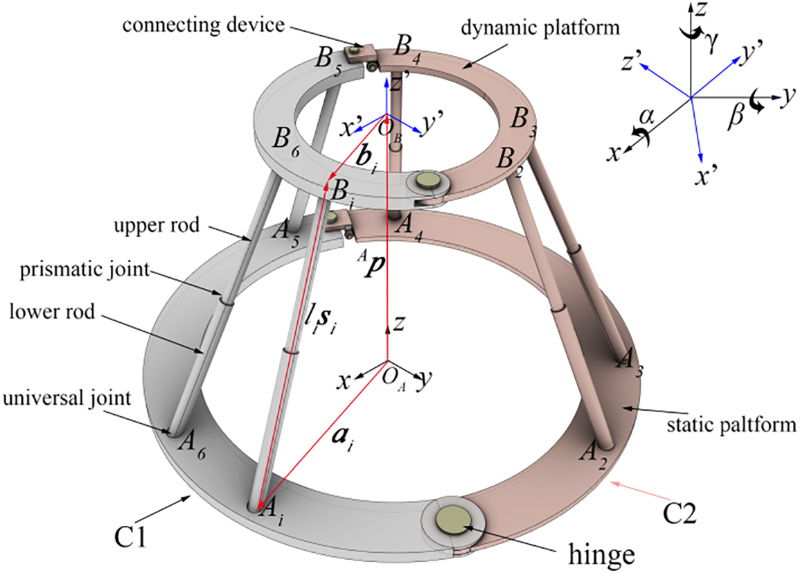
Figure 1: Coordinate system and computational model of the Stewart platform
In Fig. 1, the origin of coordinate systems
The attitude of any point on the dynamic platform is the same as the attitude of frame
where:
Suppose that the length matrix
When position
As shown in Fig. 1, the connection points between the
where:
In order to reduce the oscillation in the blade docking process, the dynamic platform was connected to the blade root. By controlling the position and attitude of the dynamic platform, the blade root was pulled to move in accordance with the desired trajectory of the platform to improve docking efficiency. This paper only considers the traction effect of the Stewart platform in the process of blade docking and ignores the possibility of collision between the blades and the hub. Therefore, the docking problem becomes fundamentally a problem with the motion control of the Stewart platform. The classical PID control algorithm [33] is adopted to control the driving force
Assuming that the desired trajectory of point
The error value
The control equation can be written as the following expression:
where:
The whole PID control process is shown in Fig. 2. The disturbing force
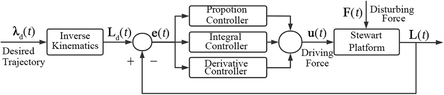
Figure 2: PID controller architecture
4 Blade Docking Simulation System
In this paper, Simulink/Simscape Multibody was used to establish the blade docking system, as shown in Fig. 3. The docking system mainly consists of three modules: Stewart platform, blades and wind load calculation. Among them, the functions of the Stewart platform module are Stewart platform building, inverse kinematics solving, and PID control. The functions of the blade module are setting up the blade model and the hoisting system, which includes the spreader, wind rope, and sling. The functions of the wind load calculation module are to simulate the wind field environment and calculate the wind load on the blades. In order to better simulate the variation of offshore wind speeds and test the effectiveness of the Stewart platform for blade motion control, the wind loads are generated through a superposition of average wind and turbulent wind. The whole simulation system ignores the influence of blade and Stewart platform deformation.
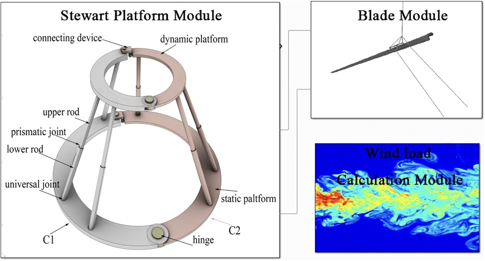
Figure 3: Composition of the docking system
The docking analysis model built by the docking system is shown in Fig. 4. The whole docking model is located in the inertial coordinate system

Figure 4: Docking system model
In the actual docking process, the blade root is maneuvered towards the hub by extending and shortening the arms of the Stewart platform. The docking process is completed when the guide bolt installed at the blade root enters the hole in the hub. After docking, the Stewart platform is removed.
5 Lifting and Alignment Simulation
In this paper, the docking system shown in Fig. 3 was used to conduct an alignment simulation for blades with a length of 61.5
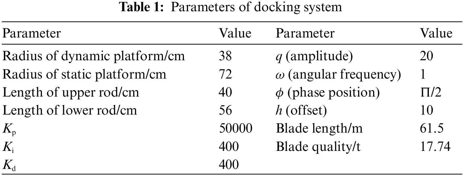
In order to ensure that the blade does not produce a large amount of shaking at the beginning and end of the docking process, the time-displacement curve of point
where:
Traditional single-blade installation must be carried out under conditions where the average wind speed is less than 12
The wind speed simulation results at the blade root obtained by the wind load calculation module are shown in Fig. 5. Since wind loads are superimposed by combining average wind and turbulent wind, the wind speed at the blade root under the three different wind fields fluctuates greatly. When the average wind speed is 12

Figure 5: Wind speed change
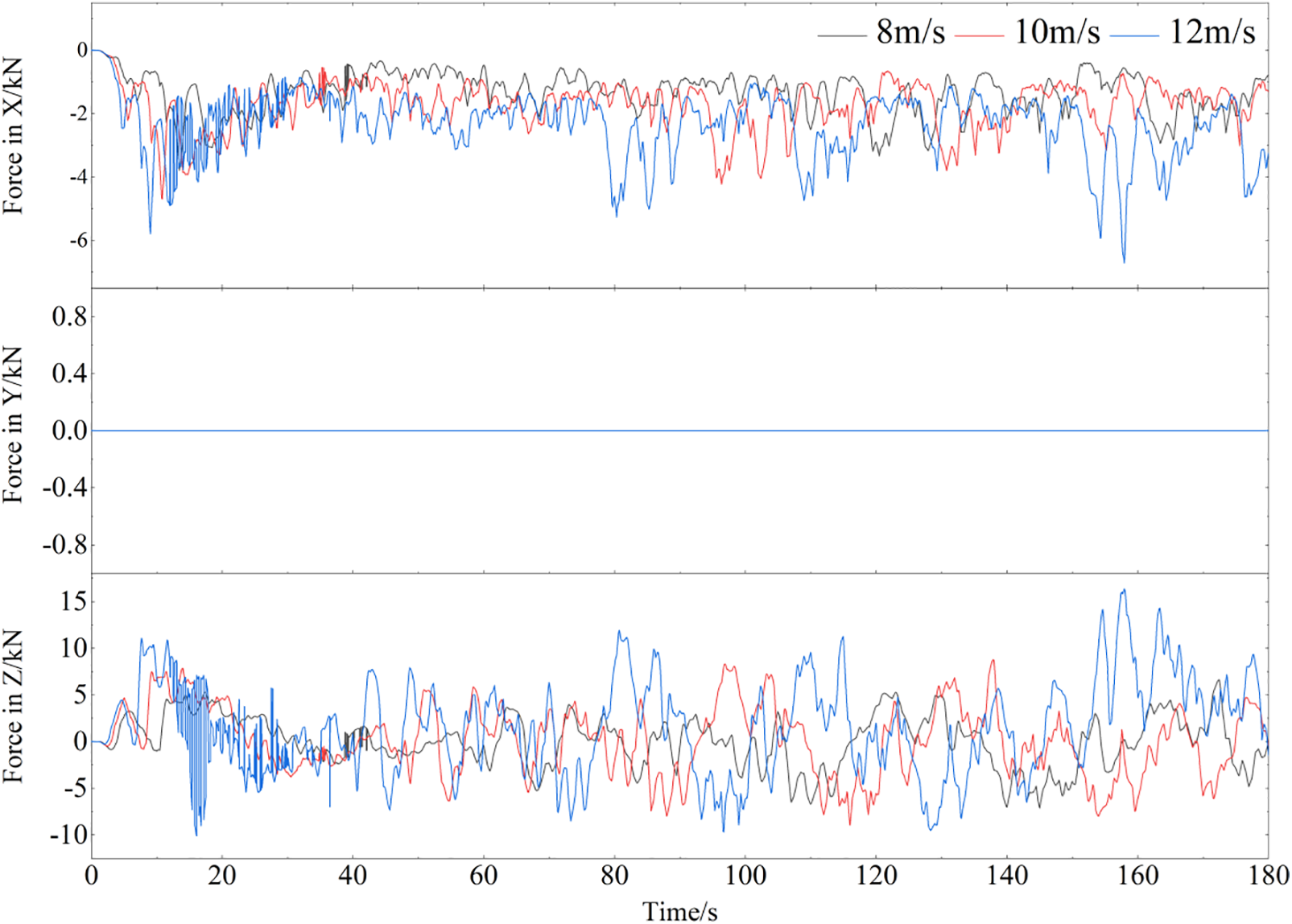
Figure 6: Wind-induced force of the blade

Figure 7: Wind-induced torque of the blade
As shown in Fig. 6, the maximum force is exerted in the
As shown in Fig. 7, the variation in amplitude of torque increases with an increase in average wind speed. When the average wind speed is 12
The blade root center approaches the hub along the expected trajectory of Eq. (9), and its displacement changes in the

Figure 8: Displacement and displacement error of blade root in Y direction

Figure 9: Displacement of blade root in X direction

Figure 10: Displacement of the blade root in Z direction
As shown in Fig. 8, under the traction of the dynamic platform, the blade root moves from 0 to 0.2 m in the Y direction, and the displacement error in the Y direction is of the order of magnitude
The changes in the attitude angle (pitch angle, roll angle, and yaw angle) at the blade root are shown in Fig. 11.

Figure 11: The changes in the attitude angle with Stewart platform
As shown in Fig. 11, the attitude angle gradually increases during the docking process. The main reason for the increase in attitude angle is that the blade root gradually deviates from its initial position due to wind load. However, when it comes to the amplitude of the attitude angle, the amplitude variation of the pitch angle, roll angle, and yaw angle are
The arm force with the largest change among the six arms are shown in Fig. 12. An increase in average wind speed results in a corresponding increase in the range of variation of arm force. Under the three wind speeds, the arm force increases continuously to maintain the stability of the blade root when the blade root gradually deviates from the initial position under the influence of high wind load.

Figure 12: The changes of arm force
In summary, in the absence of the Stewart platform to control blade root movement and in the presence of strong winds, the maximum motion displacement of blades in each direction can reach several meters only through the passive connection of wind ropes. In this case, blade docking is completely impossible. When the Stewart platform is used to control the motion of the blade roots, the blade roots can move freely along the desired trajectory. In addition, the displacement error in all directions is less than 0.04 m and the displacement error in the Y direction is less than
Based on the above research content, the main conclusions and contributions of this paper are as follows:
(1) This paper analyzes the characteristics of the Stewart platform and the difficulties of docking offshore wind turbine blades and puts forward the research direction of applying the improved Stewart platform to the docking process of offshore wind turbine blades for the first time.
(2) Based on Simulink/Simscape Multibody, this paper builds a blade docking simulation system, including the Stewart platform, blade, and wind load calculation module, which provides research tools for analyzing blade motion.
(3) According to the simulation results, the Stewart platform docking system can effectively control blade movement following a desired trajectory. The motion displacement error in the Y-axis direction is less than
This paper provides a theoretical basis for the application of the Stewart platform to the blade docking process, which will greatly improve the installation efficiency and safety of blades, reduce installation costs, and promote the development of offshore wind power.
Acknowledgement: No.
Funding Statement: The authors received no specific funding for this study.
Author Contributions: The authors confirm contribution to the paper as follows: study conception and design: Zhang Yi, Guo Jiamin; data collection: Zhang Yi; simulation model building: Zhang Yi; analysis and interpretation of results: Zhang Yi, Guo Jiamin, Peng huanghua; draft manuscript preparation: Zhang Yi, Guo Jiamin, Peng Huanghua. All authors reviewed the results and approved the final version of the manuscript.
Availability of Data and Materials: No.
Conflicts of Interest: The authors declare that they have no conflicts of interest to report regarding the present study.
References
1. Hu, W. S., Yang, X. G., Li, G. D., Guo, X. Y., Li, X. W. (2020). Analysis and suggestion of offshore wind power development of China. Electric Power Technology and Environmental Protection, 36(5), 31–36. [Google Scholar]
2. Shi, Z. Y. (2020). “Fourteen fifth plan” several considerations on offshore wind power development of China. China Power Enterprise Management, 41(13), 40–42. [Google Scholar]
3. Jiang, Z. Y. (2021). Installation of offshore wind turbines: A technical review. Renewable and Sustainable Energy Reviews, 139(44), 110576. https://doi.org/10.1016/j.rser.2020.110576 [Google Scholar] [CrossRef]
4. Zhou, G. X., Sun, H. F., Lei, C., Ge, C. (2022). Research on construction technology of 7.5 MW wind turbine blade lifting for offshore wind power. Hydropower and New Energy, 36(10), 24–27. [Google Scholar]
5. Kuijken, L. (2015). Single blade installation for large wind turbines in extreme wind conditions: A quasi-steady aeroelastic study in high wind speeds under different inflow angles (Master Thesis). Delft University of Technology & Technical University of Denmark, Netherlands & Denmark. [Google Scholar]
6. Zhao, Y. N., Cheng, Z. S., Sandvik, P. C., Gao, Z., Moan, T. (2018). An integrated dynamic analysis method for simulating installation of single blades for wind turbines. Ocean Engineering, 152, 72–88. [Google Scholar]
7. Ren, Z. R., Jiang, Z. Y., Gao, Z., Skjetne, R. (2018). Active tugger line force control for single blade installation. Wind Energy, 21(12), 1344–1358. [Google Scholar]
8. Ren, Z. R., Skjetne, R., Jiang, Z. Y., Verma, A. S. (2019). Integrated GNSS/IMU hub motion estimator for offshore wind turbine blade installation. Mechanical Systems and Signal Processing, 123, 222–243. [Google Scholar]
9. Guo, J. M., Xie, Y. Y., Zhao, Y., Hou, X. R., Song, L. (2022). Offshore wind turbine blade hoisting control based on the unscented Kalman Filter. Journal of Shanghai Maritime University, 43(2), 112–119. [Google Scholar]
10. Jiang, Z. Y., Gao, Z., Ren, Z. R., Li, Y., Duan, L. (2018). A parametric study on the final blade installation process for monopile wind turbines under rough environmental conditions. Engineering Structures, 172, 1042–1056. [Google Scholar]
11. Verma, A. S., Jiang, Z. Y., Ren, Z. R., Gao, Z., Vedvik, N. P. (2020). Effects of wind-wave misalignment on a wind turbine blade mating process: Impact velocities, blade root damages and structural safety assessment. Journal of Marine Science and Application, 19(2), 1–16. [Google Scholar]
12. Verma, A. S., Jiang, Z. Y., Vedvik, N. P., Gao, Z., Ren, Z. R. (2019). Impact assessment of a wind turbine blade root during an offshore mating process. Engineering Structures, 180, 205–222. [Google Scholar]
13. Verma, A. S., Vedvik, N. P., Haselbach, P. U., Gao, Z., Jiang, Z. Y. (2018). Comparison of numerical modelling techniques for impact investigation on a wind turbine blade. Composite Structures, 209, 856–878. [Google Scholar]
14. Verma, A. S., Jiang, Z. Y., Gao, Z., Vedvik, N. P. (2020). Effects of a passive tuned mass damper on blade root impacts during the offshore mating process. Marine Structures, 72, 102778. [Google Scholar]
15. Jiang, Z. Y. (2018). The impact of a passive tuned mass damper on offshore single-blade installation. Journal of Wind Engineering & Industrial Aerodynamics, 176, 65–77. [Google Scholar]
16. Dong, F. (2021). Dongfang wind power’s 10MW offshore wind turbine multi-functional spreader was born. Power Equipment Management, 8(2), 205. [Google Scholar]
17. Liftra (2023). LT975 blade dragon. https://www.liftra.com/products/lt975-blade-dragon?time=2023-06-27T14:54:44Z [Google Scholar]
18. High Wind, NV (2023). The boom in offshore. http://www.high-wind.eu/wp-content/uploads/2015/09/high-windpdf-159955985281.pdf [Google Scholar]
19. Liu, Y. H., An, D., Xv, Y., Shao, M., Liu, Z. P. et al. (2020). Kinematic analysis of space docking device of 6-UPS Stewart Parallel mechanism. Machine Tool & Hydraulics, 48(23), 150–154. [Google Scholar]
20. Stewart, D. (1966). A platform with six degrees of freedom: A new form of mechanical linkage which enables a platform to move simultaneously in all six degrees of freedom developed by Elliott-Automation. Aircraft Engineering and Aerospace Technology, 38(4), 30–35. [Google Scholar]
21. Gough, V. E., Whitehall, S. G. (1962). Universal tyre testing machine. Proceedings of the 9th International Automobile Technical Congress, pp. 117–137. London, UK. [Google Scholar]
22. Cerda Salzmann, D. J. (2010). Ampelmann: Development of the access system for offshore wind turbines (Master Thesis). Delft University of Technology, Netherlands. [Google Scholar]
23. FANUC (2018). F-200iB series. https://www.fanucamerica.com/docs/default-source/robotics-product-information-sheets/f-200ib-series_9.pdf?sfvrsn=f4faf90a_4 [Google Scholar]
24. Huang, Z., Kong, L. F., Fang, Y. F. (1997). Theory and control of parallel robot mechanism. China: China Machine Press. [Google Scholar]
25. Huang, T., Wang, J. S., Whitehouse, D. J. (1999). Gough-Stewart platform kinematics design theory and method. Scientia Sinica (Technologica), 1999(4), 310–320. [Google Scholar]
26. Liu, X. J. (2022). Thinking on the development of institutions and robotics. Journal of Integration Technology, 11(6), 1–4. [Google Scholar]
27. Liu, X. J. (2015). Innovation and application of robotic manufacturing equipment. 2015 China Automation Conference Abstract Collection, pp. 47. Wuhan, China. [Google Scholar]
28. Ye, P. D., You, J. J., Qiu, X., Wang, L. K., Li, C. G. et al. (2020). Research status and development trend of kinematic performance of parallel robots. Journal of Nanjing University of Aeronautics & Astronautics, 52(3), 363–377. [Google Scholar]
29. Ren, Z. R., Jiang, Z. Y., Skjetne, R., Gao, Z. (2018). Development and application of a simulator for offshore wind turbine blades installation. Ocean Engineering, 166, 380–395. [Google Scholar]
30. Jiang, J. X. (2010). Structure design and theoretical analysis of 6-PUS/UPS parallel robot (Master Thesis). Yanshan University, China. [Google Scholar]
31. Duan, Y. B., Liang, S. P., Zeng, D. X., Jiang, J. X., Zhao, Y. S. (2011). Kinematics and workspace analysis of a 6-PUS/UPU parallel robot. Journal of Machine Design, 28(3), 36–40. [Google Scholar]
32. Hamid, D. T. (2017). Parallel robots: Mechanics and control. China: China Machine Press. [Google Scholar]
33. Zhao, Y., Guo, J. M., Jiang, Z. Y., Chen, W. G., Zhou, G. G. (2022). Control method for determining feasible pre-stresses of cable-struts structure. Thin-Walled Structures, 174, 109159. [Google Scholar]
Cite This Article
 Copyright © 2023 The Author(s). Published by Tech Science Press.
This work is licensed under a Creative Commons Attribution 4.0 International License , which permits unrestricted use, distribution, and reproduction in any medium, provided the original work is properly cited.
 Downloads
 Citation Tools