
 Submit a Paper
 Propose a Special lssue
 Open Access
ARTICLE

Model Predictive Control Strategy of Multi-Port Interline DC Power Flow Controller
1 Key Laboratory of Modern Power System Simulation and Control & Renewable Energy Technology, Ministry of Education (Northeast Electric Power University), Jilin, 132012, China
2 Marketing Department, State Grid Jilin Electric Power Co., Ltd., Changchun, 130061, China
* Corresponding Author: Bian Jing. Email:
(This article belongs to the Special Issue: Advances in Modern Electric Power and Energy Systems)
Energy Engineering 2023, 120(10), 2251-2272. https://doi.org/10.32604/ee.2023.028965
Received 19 January 2023; Accepted 05 May 2023; Issue published 28 September 2023
 View Full Text
 Download PDF
Abstract
There are issues with flexible DC transmission system such as a lack of control freedom over power flow. In order to tackle these issues, a DC power flow controller (DCPFC) is incorporated into a multi-terminal, flexible DC power grid. In recent years, a multi-port DC power flow controller based on a modular multi-level converter has become a focal point of research due to its simple structure and robust scalability. This work proposes a model predictive control (MPC) strategy for multi-port interline DC power flow controllers in order to improve their steady-state dynamic performance. Initially, the mathematical model of a multi-terminal DC power grid with a multi-port interline DC power flow controller is developed, and the relationship between each regulated variable and control variable is determined; The power flow controller is then discretized, and the cost function and weight factor are built with numerous control objectives. Sub module sorting method and nearest level approximation modulation regulate the power flow controller; Lastly, the MATLAB/Simulink simulation platform is used to verify the correctness of the established mathematical model and the control performance of the suggested MPC strategy. Finally, it is demonstrated that the control strategy possesses the benefits of robust dynamic performance, multi-objective control, and a simple structure.Keywords
Flexible DC transmission technology with the advantages of independent control of active and reactive power and no phase change failure has been recognized as an effective solution to the problem of renewable energy grid connection and electricity consumption [1,2] due to the rapid development of new energy generation. Flexible DC grids have increased grid redundancy and enhanced transmission reliability than a standard DC grid. However, it can pose challenges for the power system, such as challenging current regulation and sophisticated fault protection. If there are more than N-1 lines in a DC grid with N converter stations, the converter stations cannot manage the currents on all lines individually. In order to improve the flexibility of DC grid power flow control, a further type of power electronics-based device, the DCPFC [3], is introduced into the DC grid.
Among the many DCPFC topologies, interline DCPFC (interline direct current power flow controller, IDCPFC) does not require additional power supply and has a greater advantage in terms of engineering feasibility and technical economy. The first IDCPFC topology with dual H-bridges back-to-back was proposed in reference [4], and the loss of the dual H-bridge structure is about 2.4% of that of the varactor topology at 1 kA DC current. Compared with the dual H-bridge interline DC current controller, the single capacitor interline DC current controller proposed in reference [5] was able to save 33% of power electronics in the unidirectional current condition, but still does not solve the current ripple problem caused by individual capacitor charging and discharging. Reference [6] also proposes a power electronics saving DCPFC topology and designed an hysteresis band current control (HCC) based control system for its proposed DCPFC. Reference [7] extended the dual H-bridge interline DC current controller to multiple transmission lines with fewer power electronics used, but the interline DC current controller with a single capacitor has very limited expansion capability. Reference [8] compared different power flow control methods and uses a dual H-bridge back-to-back IDCPFC topology in reference [4] to study the role of DC power flow controller, where power flow current control is achieved by connecting a single capacitor to 2 lines at high frequency.
In recent years, DCPFCs based on modular multi-level converters (MMC) have attracted a great deal of interest. MMCs offer numerous advantages, including adaptability, controllability, superior power quality, and high power transmission capacity. Numerous writers [9–12] have proposed their very own MMC-based DCPFCs by combining different MMC characteristics. By adjusting the number and direction of sub-module inputs in a single bridge arm, which has the benefits of a simple structure and easy extension into multi-ports, these DCPFCs make use of the operating characteristics of MMC sub-modules to meet the requirements of power quality and control effects.
Concerning the DCPFC control strategy, the bulk of previously published articles [13–15] have established control strategies for their proposed DCPFC topologies; however, they are all standard linear control strategies based on the proportional-integral (PI) control technique. Using the PI control methodology, reference [16] developed and analyzes the mathematical model of a three-terminal DC grid with a DCPFC placed between two lines. Reference [17] proposed an expandable N-interline DCPFC and a control method based on proportional-integral-derivative (PID) control. Other publications have created control strategies for DCPFCs operating under specific conditions. Specifically, reference [18] examined a successful control strategy and the damping control mechanism of the DCPFC under sub-synchronous oscillations. The problem of a shift in the control degree of freedom caused by a non-transient disconnection defect in the DC ring grid is addressed in the study [19] by the creation of a control degree switching method for DCPFC. Reference [20] provided a control strategy for coordinated management of DCPFC and DC circuit breakers in order to reduce fault currents during DC faults.
Numerous investigations on DCPFC topologies and control strategies have been conducted in recent years. MPC is a nonlinear predictive control system that predicts controlled quantities and completes control using a predictive model of future states and online cyclic optimization calculations. In the area of process control, it has been successfully used in [21,22]. Power electronics and transmission control have seen a lot of study on finite control set model predictive control (FCS-MPC) over the past ten years. For the first time, FCS-MPC is utilized in [23] to control the MMC-HVDC system. MPC is also used in [24] to regulate the MMC’s AC output current, and loop control is added to complete multi-objective control. In order to lower the computational cost of the MPC and increase the computational speed, a voltage sequencing algorithm is added to the control strategy [25]. To further reduce the computational cost when utilizing the voltage sequencing technique, reference [26] substituted a finite control set of output level numbers for the conventional effective switching state finite control set. In reference [27], to guarantee the output voltage’s consistency, the number of bridge arm input modules is only allowed to fluctuate within a small range throughout the subsequent sampling time. This prevents the output voltage from changing too quickly.
In conclusion, DCPFC’s steady-state control strategy is mostly built on the typical linear control strategy based on PI control, while MPC is not yet implemented. In order to improve the dynamic performance of the MMC-based DCPFC, a MPC strategy is suggested for the novel multi-port interline power flow controller (MI-PFC), established in reference [28], in this paper. On the basis of the original topology and power flow control technique, a mathematical model of the multi-terminal DC grid comprising the MI-PFC is developed, and a MPC strategy for the MI-PFC with optimum steady-state operating performance is subsequently devised. In order to test the performance of the control strategy, the MI-PFC electromagnetic transient model is constructed using the MPC strategy and the MATLAB/Simulink simulation tool.
Fig. 1 depicts the topology of the MI-PFC employed in the article. Full-bridge submodule forms the foundation for the MMC bridge arm. The primary components of the DC current controller are the equivalent resistor R1, capacitor C1, bridge arm reactor L1, and DC reactor Ldc. The AC and DC routes of the MI-PFC, which consist of capacitor C1 and DC reactor Ldc, keep the AC and DC currents separate. The MMC bridge arm can be utilized as a modular device and is therefore easily expandable, allowing the number of sub-modules and bridge arms to be altered as needed to fulfill power quality specifications.
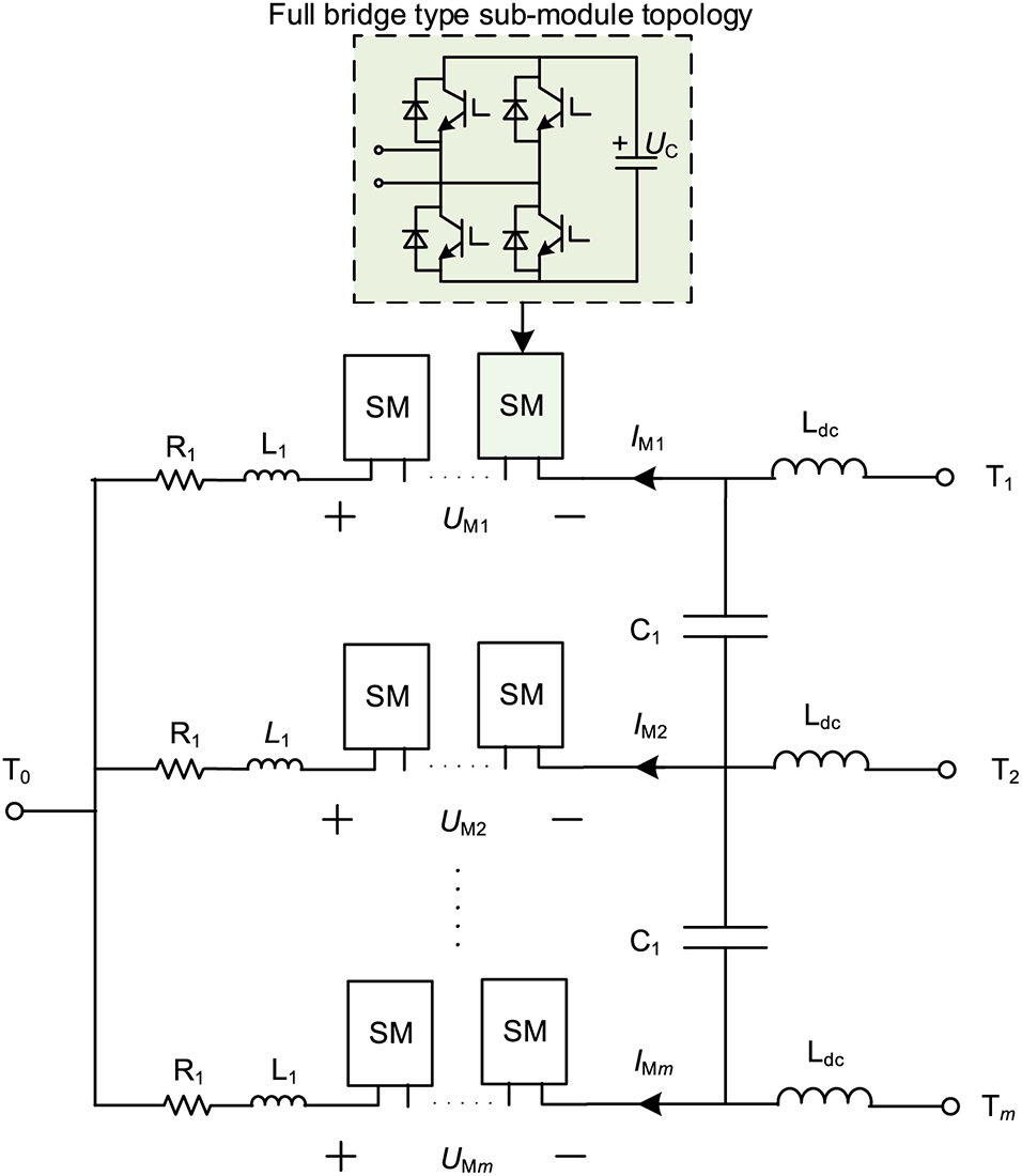
Figure 1: Topology of MI-PFC
3 MI-PFC Working Principle and Mathematical Model
MPC requires a discrete mathematical model to foresee future states. Consequently, it must be designed with MI-PFC-specific architecture and actual operating conditions in mind. After introducing the topology of MI-PFC in the preceding section, this section establishes the dynamic mathematical model of MI-PFC by analyzing its operating principle, then provides the discrete mathematical model required in MPC by discretizing it, and finally derives the necessary equation for prediction.
In a four-terminal DC grid, the three-port MI-PFC is installed at the site of converter station 1 as illustrated in Fig. 2, where Iij represents the line current, Rij represents the DC line resistance, Ui represents the voltage at the converter station, and Ii represents the outlet current.
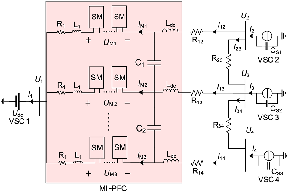
Figure 2: Equivalent circuit diagram of power flow control
The interline DC current controller must have both the basic function of controlling current and the ability to balance its own power. Consequently, the MI-PFC bridge arm voltage is given by Eq. (1).
where UMiDC is the amplitude of the DC component of the voltage at both ends of the MMC and UMiAC is the amplitude of the AC component of the voltage at both ends of the MMC; the former is responsible for controlling the grid current and the latter for balancing its own power; θi is the initial phase angle of the AC component (i = 1~3).
A few kilovolts of voltage drop in a DC grid line is negligible compared to typical system-level values of several hundred kilovolts. Consequently, a minimal number of UM1DC–UM3DC submodules of the MMC full-bridge variety can perform the role of controlling DC grid currents. The DC grid depicted in Fig. 2 is controlled by master-slave control, with converter station 1 adopting a constant voltage control strategy and the other three converter stations using a constant power control strategy.
Therefore, the currents I2~I4 at the converter station can be considered known quantities. Fig. 2 illustrates the relationship between DC voltage and line current according to Kirchhoff’s voltage law.
where I12, I13, I14, I23, and I34 are the line currents as shown in Fig. 2; IM1, IM2, and IM3 are the bridge arm currents as shown in Fig. 2; I2, I3, and I4 are the converter station currents as shown in Fig. 2; R12, R13, R14, R23, and R34 are the line resistances in Fig. 2.
In addition, the entire power of the MMC bridge arm of the MI-PFC must be balanced, and the AC power of the MI-PFC can only be exchanged inside it so that it can achieve its intended function of power balancing. To generate matched bridge arm currents, the MMC bridge arm voltage consists of both DC and AC components, as stated in the following Eq. (3). In the MI-PFC topology, C1 is responsible for “blocking DC current and passing AC current,” whereas Ldc is responsible for “blocking AC current and passing DC current.” The existence of the DC reactor Ldc prevents the AC current of the MI-PFC from migrating to the DC grid line, causing it to flow only within the reactor.
where IMiAC is the AC current fundamental amplitude of the bridge arm current, and
In each bridge arm of the MI-PFC, there are N full-bridge sub-modules, and it is assumed that each sub-module receives a voltage of UMiC. The following will serve to establish the relationship between the number of sub-modules, the voltage of each individual sub-module, and the voltage of each bridge arm.
where UMi is the bridge arm voltage, N is the number of submodules, and UMiC is the submodule capacitance voltage (i = 1~3).
The bridge arm containing N sub-modules is analogous to a whole capacitor, and the voltage on each bridge arm is determined by
where UMi is the bridge arm voltage, IMi is the bridge arm current and Ceq is the equivalent capacitor, and its value can be expressed as
where C is the capacitor value of each submodule.
The KCL equation for the capacitor between the two bridge arms is given as
where UC1 and UC2 are the voltages of the capacitors C1 and C2 between the bridge arms.
The mathematical model presented in the paper depicts station 1’s constant voltage converter as being equivalent to the DC voltage source Udc. The current source shunt capacitor is equated to the remaining three converter stations. The equivalent KCL equations for these three converter stations are listed below:
where U2, U3, and U4 and refer to the voltage of converter station 2, 3, and 4, respectively. CS2, CS3, and CS4 are the equivalent capacitors of the converter stations.
Following is how the final dynamic mathematical model of MI-PFC is obtained:
where A and B are matrices of coefficients.
MPC requires a discrete MI-PFC dynamic mathematical model; hence, the aforementioned dynamic mathematical model is discretized using the forward Euler method, as indicated in Eq. (12).
where x(k + 1) is the value of the variable at the next sampling time, x(k) is the value of the variable at the current sampling time, and Ts is the sampling cycle time.
4.1 The Overall Control Structure
The completion of MI-PFC’s primary core function is dependent on the MMC full-bridge sub-module; thus, the initial control strategy also employs the direct current control method based on the PI control strategy, which is a standard linear control strategy. The direct current control method is separated into an outer-loop controller and an inner-loop current controller, requiring the setting of proportional and integral coefficients for the two control loops, resulting in a more complicated control structure. Moreover, when the control target is quickly altered, the linear control features of PI control would result in poor dynamic performance. As a nonlinear optimal control strategy, MPC has many benefits, including simple control structure, multi-objective control, and good dynamic performance. Consequently, with the rapid development of digital processors, FCS-MPC has been widely studied in the fields of power electronics and power drives. The principle of MPC is to obtain the predicted value of the controlled quantity at the next sampling time using a model predictive method under the action of a limited combination of switch states, thereby obtaining the optimal switch group state combination.
Therefore, the paper chooses model predictive control instead of conventional PI-based control for current and voltage control in MI-PFC. The overall structure of the proposed model predictive control strategy is described in detail below.
Fig. 3 illustrates that the MI-PFC MPC strategy encompasses five essential components, comprising a discrete prediction model, reference value computation, model prediction, rolling optimization, sub-module voltage ordering, and nearest level approximation modulation. Included in the calculation of the reference value are the bridge arm voltage command and line current command reference values. The discrete MI-PFC mathematical model computes the bridge arm voltage and line current prediction values at the next sampling instant, inputs them into the defined cost function, and then performs rolling optimization to determine the ideal number of input submodules. In order to limit the rate of voltage change so that the bridge arm voltage does not fluctuate drastically and abruptly, the MPC strategy proposed in the paper limits the number of submodule inputs to the range −1, 0, and 1, i.e., only up to one submodule can be increased, decreased, or held constant.
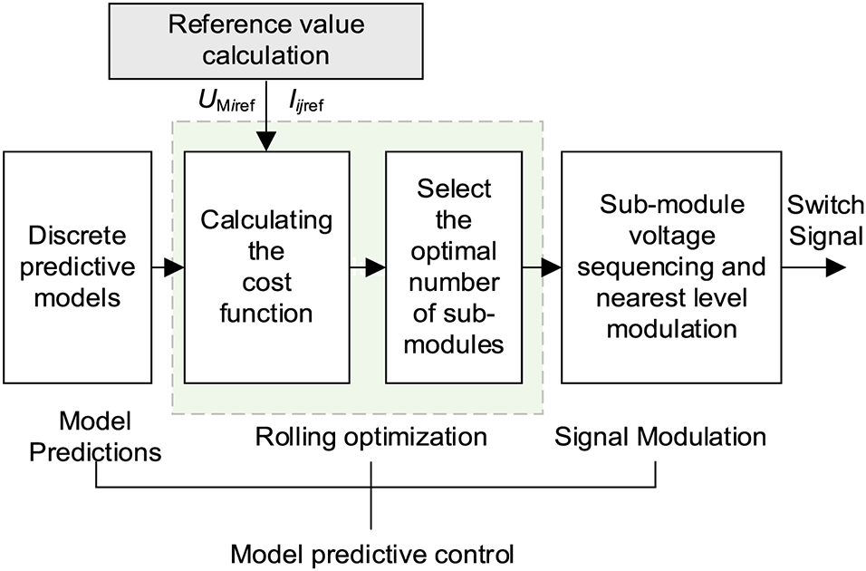
Figure 3: Block diagram of MPC strategy for MI-PFC
After establishing the ideal number of input submodules, N, submodule voltage sorting is used to balance the submodule capacitor voltage. Due to the low voltage level of MI-PFC, a small number of full-bridge submodules are utilized. In the sorting method, traditional bubble sorting is utilized, which compares the voltage of each submodule to the others and selects the submodule with the lowest voltage while charging and the submodule with the greatest voltage when discharging. Thus, the required sub-module can be chosen so that the voltage in the full-bridge type sub-module within the bridge arm can be kept as consistent as feasible, and the computing work of the MPC strategy can be minimized to some degree. The mathematical model is given as
where UMiC is the sub-module capacitor voltage.
Using nearest level modulation (NLM), the final modulation signal is created for input into the IGBT of the submodule. Us(t) is supposed to represent the instantaneous value of the modulating wave, and UC represents the output voltage level span, where UC is equal to the average value of the sub-module capacitor voltage for a well-balanced sub-module voltage. After each sampling interval, the reference wave Us(t) is sampled, and N sub-modules are inserted into the bridge arm between each sampling period. The expression of the relationship is as follows:
where the round (x) function returns the integer that is closest to x.
Since the MI-PFC used in the paper relies on the forward and reverse inputs of full-bridge submodules to complete the bidirectional control of the DC grid power flow, the calculated number of submodule inputs ranges from N, where a submodule input number greater than zero indicates the forward input of submodules and a submodule input number less than zero indicates the reverse input of submodules.
4.2 Reference Value Computation
MI-PFC generates amplitude UMiDC and UMiAC DC voltage components and AC voltage components, the former of which is responsible for achieving the objective of managing grid currents and the latter of which is responsible for achieving the goal of balancing its own power.
In addition, Eq. (15) depicts the DC line currents in Fig. 2.
where Pij is the line power, Ui is the converter station voltage, and Iij is the line current (i = 1~3, j = 1~4).
It can be inferred that the value of Ui in Eq. (15) remains consistent, enabling the tidal current controller to implement a mechanism that governs the line current with the intention of regulating the tidal current. Consequently, the line current and the bridge arm voltage are the two control objectives of the MI-PFC, and their respective reference values must be calculated. In Fig. 4, Iijref is the DC line current reference value that is determined by the power flow control objective. Using the known line resistance and the constant power converter station current, i.e., UMiref in Fig. 4, it is possible to determine the bridge arm voltage reference value while adjusting the power flow current. Its specific computation can be taken from the literature on steady-state control strategies [28].
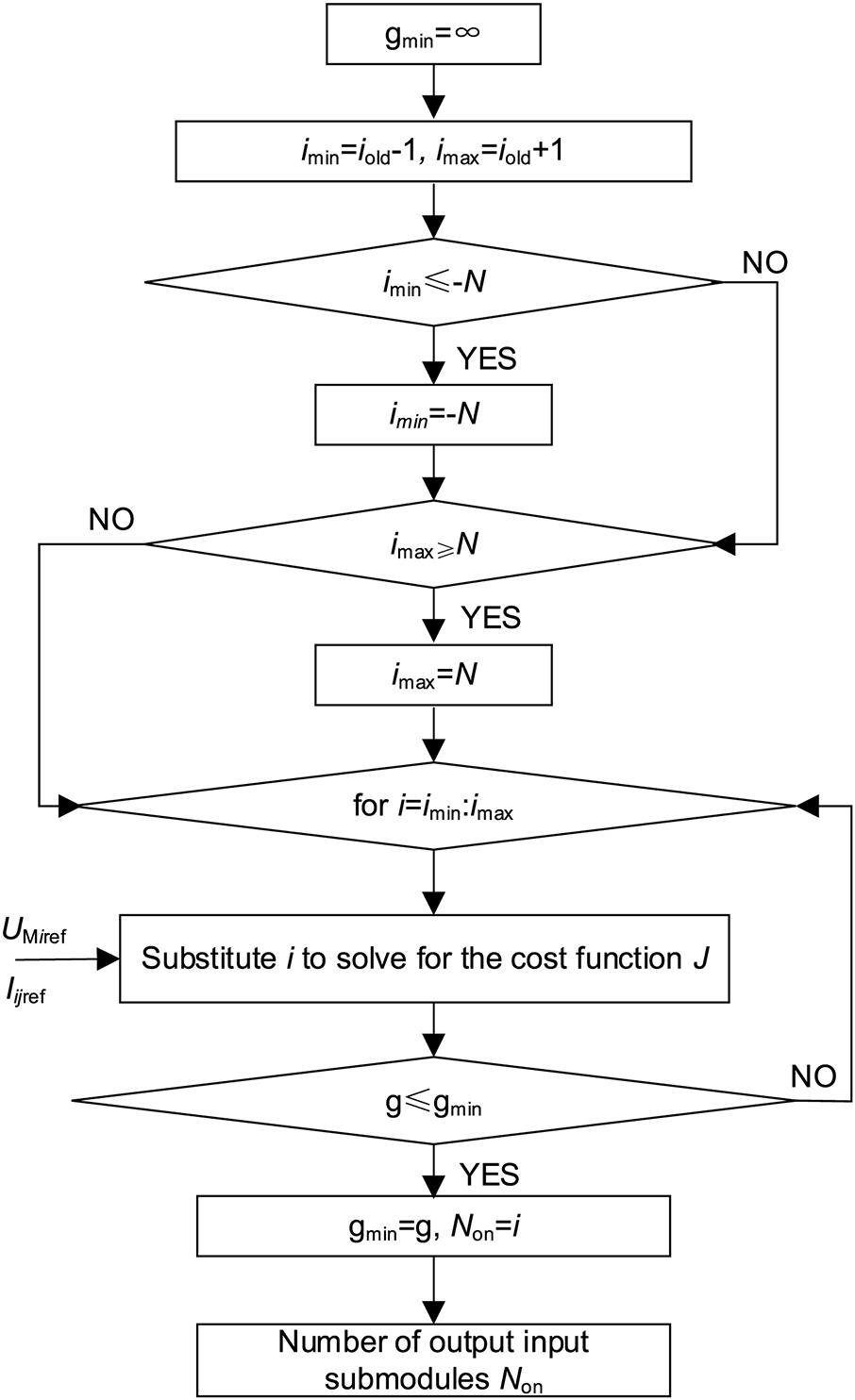
Figure 4: Sub-module input quantity calculation method
4.3 Constructing the Cost Function
The two control objectives of the MI-PFC MPC strategy are bridge arm voltage and line current, and these two control quantities are included in the design of the cost function. Incorporating a weighting component into the multi-objective control problem further integrates it. Cost functions are created in accordance with the aforementioned control objectives.
(1) Bridge arm voltage
According to the discrete mathematical model of MI-PFC presented in the preceding section, the bridge arm voltage prediction equation can be derived as
where UMi(k + 1) is the predicted value of the bridge arm voltage at the next sampling time, UMi(k) is the actual value of the bridge arm voltage at this time, and Ts is the sampling time.
Therefore, the cost function for the control objective of the bridge arm voltage can be designed as follows:
where UMiref is the bridge arm voltage reference value.
(2) Line current
The power distribution of a DC grid is determined by the direction and magnitude of the current on each line. Consequently, line current is the ultimate aim of DC current control. In the initial DC current control strategy, the bridge arm voltage command reference value is derived from the line current command reference value. The MPC strategy for MI-PFC directly uses the line current as a control target, which will manage the DC grid power flow more directly and more quickly, and is vital for enhancing the MI-PFC strategy’s dynamic performance.
According to the discrete mathematical model of MI-PFC, the following line current prediction equation can be derived:
where Iij(k + 1) represents the anticipated value of the line current at the next sampling time, Iij(k) represents the actual value of the line current at this time, and Ts represents the sampling time.
Consequently, the cost function for the line current control goal can be constructed as follows:
where Iijref is the line current reference value.
Combining the aforementioned two control objectives, the overall cost function is created according to Eq. (20), where the weight factor must be found through trial generation and λ1 = 0.01, λ2 = 0.2 are assumed in the study.
where λ1, λ2 are the weight factors.
The dynamic mathematical model of the four-terminal DC grid comprising MI-PFC established in the previous publication is simulated in the form of a MATLAB program, and the electromagnetic transient model of MI-PFC employing a PI-based technique is constructed in MATLAB/Simulink. The specific parameters are shown in Tables 1–4. The following simulations are done for the MI-PFC during normal operation. The length of lines L12/L14 is 2 km, and the length of lines L13/L23/L34 is 1 km.


The model validation was performed by comparing the dynamic mathematical model of MI-PFC and the electromagnetic transient model under operating condition 1 as shown in Table 5 to verify the correctness and validity of the dynamic mathematical model used in the paper.

Figs. 5a and 6b depict the currents of each line of MI-PFC for the two models of four-terminal DC grids simulated by the MATLAB software, whereas Figs. 5c and 5d depict the voltages of the converter station simulated by the two models. UM1C, UM2C, and UM3C are the dynamic mathematical models simulated by the submodule capacitor voltages simulated by the dynamic mathematical model in Figs. 5e and 5f. The comparison in Fig. 5 demonstrates that the DC current, converter station voltage, and sub-module capacitor voltage simulated by the dynamic mathematical model are highly consistent with the MI-PFC electromagnetic transient model employing the original PI control strategy, and the error is due to the fact that the mathematical model disregards the high harmonic components of the internal AC voltage of the MI-PFC. The above analysis demonstrates the correctness and precision of the article’s dynamic mathematical model of MI-PFC.

Figure 5: Model verification simulation diagram

Figure 6: Simulation comparison of line current under condition 1
5.2 Verification of the Performance of the MI-PFC Model Control Strategy
To further demonstrate the benefits of the MPC strategy for MI-PFC, an electromagnetic transient model of the MI-PFC is constructed and simulated in MATLAB/Simulink. The parameters utilized in the preceding mathematical model are maintained.
(1) Condition 1: The current on control line L13 falls as the current on control line L14 rises.
Before MI-PFC is activated, the DC grid is stabilized with the following line currents: I12 = 0.767 kA, I13 = 1.8 kA, I14 = 0.933 kA, I34 = −0.067 kA, and I23 = −0.267 kA. To maintain the consistency of the MPC strategy and the sampling frequency of nearest level approximation modulation, the sampling period for the main circuit parameters and the operation parameters of the Dinghai converter station of the Zhoushan multi-terminal flexible DC transmission project is set to 100 μs. The key control parameters in the simulation system are shown in Table 6. I13 = 1.5 kA and I14 = 1.5 kA are the power flow current control goals for condition 1 at t = 1 s. According to the operating principle described in the preceding study, the bridge arm voltage reference value is as shown in Table 5.
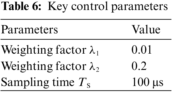
Fig. 6a depicts the distribution of DC grid current. During this procedure, the power flow controller adjusts I13 and I14 to the desired values in approximately 0.3 s. Fig. 6b depicts the line currents regulated by the MPC strategy technique described in the article, in which this power flow controller brings I13 and I14 to the desired control value in around 0.2 s. From Fig. 6b, it can be observed that the DC current with the MPC strategy follows the reference value more quickly and steadily, and its fluctuations are lower than those with the original control strategy. Therefore, when the DC current controller is activated, the effect on the current of each line of the DC grid can be enhanced.
Compared to the bridge arm voltages UM1, UM2, and UM3 in Fig. 7a with PI control, the bridge arm voltages UM1, UM2, and UM3 in Fig. 7b with MPC strategy demonstrate that the MPC strategy designed in this paper provides superior control dynamic performance for the bridge arm voltages. As illustrated in Fig. 7a, the bridge arm voltage under PI controlled condition 1 begins to vary significantly at 1.01 s, whereas in Fig. 7b, the bridge arm voltage under MPC control strategy of condition 1 begins to change significantly only at 1.002 s.
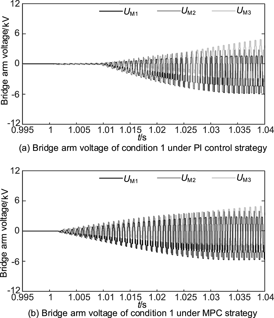
Figure 7: Simulation comparison of bridge arm voltage under condition 1
In accordance with the paper’s MPC strategy, the submodule capacitor voltage can follow the reference value more quickly based on the simulation comparison in Fig. 8. In conjunction with the sub-module balancing algorithm, it can maintain the balance and stability of the sub-module capacitor voltage in the MI-PFC bridge arm. Similarly, the peak value of UM3C in Fig. 8b is lower than that in Fig. 8a due to the more accurate following ability of submodule voltage brought about by the MPC strategy, indicating that the overcharging problem at the initial charging of submodule capacitor under PI control can be mitigated to some degree.

Figure 8: Simulation comparison of sub-module capacitor under condition 1
(2) Condition 2: The current on line L13 decreases and the current on line L14 increases.
After the DC grid is stabilized, the power flow control target for MI-PFC at t = 1 s in condition 2 is set at I13 = 1 kA and I14 = 0.5 kA, and the sampling time is also 100 μs. The reference values of the bridge arm voltage in Condition 2 are shown in Table 7.

In Fig. 9b, I13 and I14 are the DC line currents of condition 2 with the MPC strategy, and it can be seen that I13 and I14 can be reduced to the target value in Fig. 9b. In terms of the dynamic performance of the line current control in condition 2, the original PI control can be completed in about 0.3 s to follow the line current reference value, while the MPC strategy can be completed in about 0.2 s to basically follow the line current reference value. At the same time, the fluctuation of the current magnitude will be reduced.

Figure 9: Simulation comparison of line current under condition 2
Fig. 10b depicts the bridge arm voltages in the DC grid under the MPC strategy, while Fig. 10a depicts the bridge arm voltages with the original PI control strategy. Comparing the two figures reveals, similar to condition 1, that the bridge arm voltage under the MPC strategy responds approximately 0.098 s faster than the bridge arm voltage under PI control.
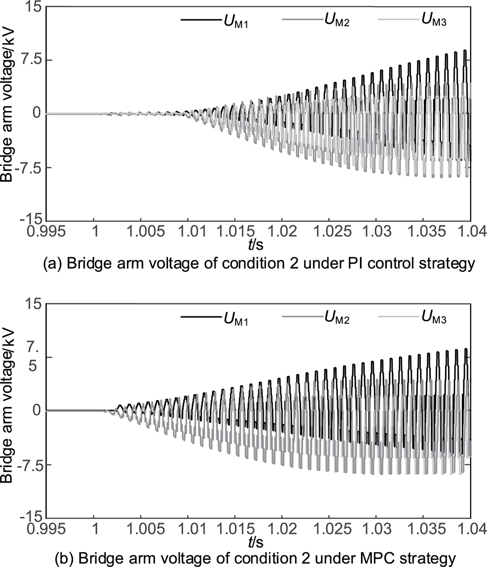
Figure 10: Simulation comparison of bridge arm voltage under condition 2
In Fig. 11b, the submodule capacitor voltages UM1C, UM2C, and UM3C under the MPC strategy have a faster control target tracking speed than the submodule capacitor voltages UM1C, UM2C, and UM3C with the original PI control strategy. Comparing the peak value of UM1C in Figs. 11b and 11a, there is a reduction utilizing the MPC strategy designed in the study, demonstrating that the control strategy can mitigate the problem of submodule capacitor overcharging to some extent.

Figure 11: Simulation comparison of sub-module capacitor under condition 2
The simulation analysis of the aforementioned two operating conditions demonstrates that the MPC strategy designed in this paper can control line current, bridge arm voltage, and sub-module voltage effectively under different operating conditions and has a faster dynamic response and more accurate control effect than the original control strategy for the designed control target.
5.3 Precharge Method for MI-PFC
Incorporating an initial energy for the storage element in the MI-PFC can effectively minimize the intensity of the transient process, which subsequently helps reduce the voltage shock during the start-up phase [29]. Therefore, this research endeavors to include a precharge method in the start-up process by following the subsequent steps:
(1) Firstly, the sub-module will be blocked so that the DC line current charges the sub-module of the MMC bridge arm. The sub-module capacitors will have an uneven charging rate due to the varying DC line current. Therefore, to avoid over-voltage, the sub-module will be unblocked once the capacitor of the largest sub-module in all bridge arms reaches 85% of the rated value. The sub-module capacitor will then store energy.
(2) Secondly, the sub-module will be removed to enable the DC line current to magnetize the inductor L1. During the initial stage, the charging current will decrease as the capacitor voltage rises, leading to an inability to magnetize the bridge arm inductor. However, after removing the sub-module, the DC line current starts to magnetize the inductor, with IM1 − IMi indicating the magnetization is complete, and the MI-PFC is ready for power flow control.
As shown in Figs. 12 and 13, simulation experiments were conducted to demonstrate the effect of the precharge method on the control of sub-module capacitor voltage fluctuations. The simulation results show that the voltage fluctuation of small module capacitors can be reduced by adding the precharge method, and the parameters of the capacitor and IGBT can be more easily selected.
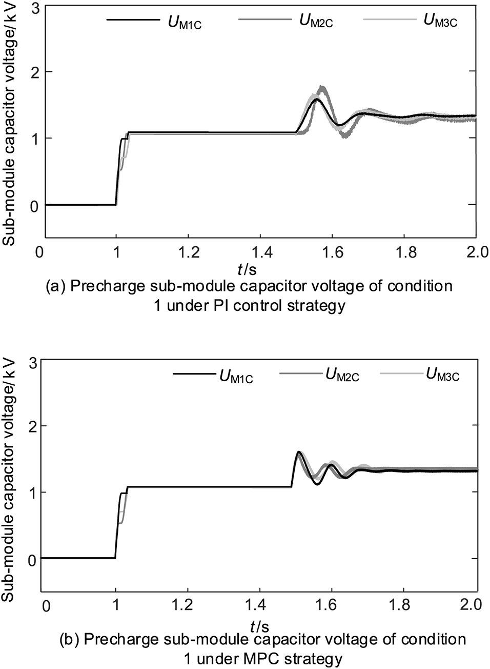
Figure 12: Precharge sub-module capacitor voltage of condition 1
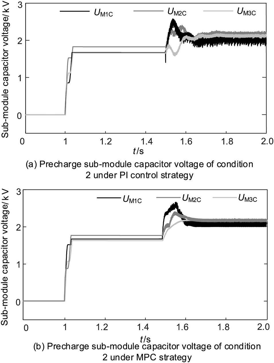
Figure 13: Precharge sub-module capacitor voltage of condition 2
The article proposes a MPC strategy for the MI-PFC that has the benefits of good dynamic performance, a simple control structure, and the ability to implement multi-objective control. The subsequent conclusions are reached:
(1) The MPC strategy presented in this study can replace the original PI-based voltage control and current control structures. It has two control objectives: DC line current and bridge arm voltage.
(2) The dynamic mathematical model of a multi-terminal DC grid with a MI-PFC can accurately represent the relationship between each controlled quantity and the control quantity, thereby achieving the prediction output of voltage and current commands and completing the model prediction link of the paper’s control strategy.
(3) The MPC strategy created in this study has a certain degree of dynamic performance improvement and optimization compared to the original control strategy; it also has greater control accuracy and simplifies the construction of the control strategy for the MI-PFC. The model predictive control strategy designed in the article can improve the DC line current control speed by 30%, and the control time to complete the line current in the four-terminal DC network used in the MPC strategy in the article is 0.2 s, which saves 0.1 s compared to PI control. Under the PI control strategy, the bridge arm voltage starts to change significantly at t = 1.01 s, while with the MPC control strategy, the bridge arm voltage starts to change significantly at t = 1.002 s the bridge arm voltage strategy starts to change significantly, which is about a 20% improvement in dynamic response speed.
(4) The paper utilizes a model predictive control approach to enhance the control performance of MI-PFC. A cost function is employed to normalize the two control objectives; however, certain limitations still exist. The cost function used in the study relies on the traditional trial generation method, which may be challenging and time-consuming in determining the process. Additionally, the capacitor voltage sorting technique utilized in the research is based on the traditional bubble sorting algorithm, which requires a substantial amount of computation. Voltage sorting algorithm used is the traditional bubble sorting, which requires a large amount of calculation.
(5) Moreover, while MI-PFC is a unique inter-line DCPFC topology, the model predictive control strategy developed may not be suitable for other inter-line DC current controllers. Therefore, proposed extensions to more interline DC current controllers utilizing general models will be explored in future studies to enhance the scope of this research.
Acknowledgement: None.
Funding Statement: The research is funded by National Natural Science Foundation of China (52177074).
Author Contributions: The authors confirm contribution to the paper as follows: study conception and design: He Wang, Jing Bian; data collection: Guanye Shen; analysis and interpretation of results: He Wang, Xiangsheng Xu, Jing Bian; draft manuscript preparation: Xiangsheng Xu, Jing Bian. All authors reviewed the results and approved the final version of the manuscript.
Availability of Data and Materials: The authors confirm that the data supporting the findings of this study are available within the article. And the additional data that support the findings of this study are available on request from the corresponding author, upon reasonable request.
Conflicts of Interest: The authors declare that they have no conflicts of interest to report regarding the present study.
References
1. Tang, G. F. (2010). High voltage DC transmission technology based on voltage source converter. China: China Electric Power Press. [Google Scholar]
2. Zhao, C. Y. (2014). Modeling and simulation techniques for flexible DC power transmission. China: China Electric Power Press. [Google Scholar]
3. Gomis-Bellmunt, O., Sau-Bassols, J., Prieto-Araujo, E., Cheah-Mane, M. (2019). Flexible converters for meshed HVDC grids: From flexible AC transmission systems (FACTS) to flexible DC grids. IEEE Transactions on Power Delivery, 35(1), 2–15. https://doi.org/10.1016/j.rser.2016.11.233 [Google Scholar] [CrossRef]
4. Barker, C. D., Whitehouse, R. S. (2012). A current flow controller for use in HVDC grids. 10th IET International Conference on AC and DC Power Transmission (ACDC 2012), pp. 1–5. Birmingham, UK, IET. https://doi.org/10.1049/cp.2012.1973 [Google Scholar] [CrossRef]
5. Sau-Bassols, J., Prieto-Araujo, E., Gomis-Bellmunt, O. (2015). Modelling and control of an interline current flow controller for meshed HVDC grids. IEEE Transactions on Power Delivery, 32(1), 11–22. https://doi.org/10.1109/TPWRD.2015.2513160 [Google Scholar] [CrossRef]
6. Diab, H. Y., Marei, M. I., Tennakoon, S. B. (2016). Reduced switch count topology of current flow control apparatus for MTDC grids. Journal of Power Electronics, 16(5), 1743–1751. https://doi.org/10.6113/JPE.2016.16.5.1743 [Google Scholar] [CrossRef]
7. Diab, H. Y., Marei, M. I., Tennakoon, S. B. (2016). Operation and control of an insulated gate bipolar transistor-based current controlling device for power flow applications in multi-terminal high-voltage direct current grids. IET Power Electronics, 10(2), 305–315. https://doi.org/10.1049/iet-pel.2015.0525 [Google Scholar] [CrossRef]
8. Diab, H., Tennakoon, S., Gould, C., Marei, M. I. (2015). An investigation of power flow control methods in multi terminal high voltage DC grids. 2015 50th International Universities Power Engineering Conference (UPEC), pp. 1–5. Stoke on Trent, UK, IEEE. https://doi.org/10.1109/UPEC.2015.7339839 [Google Scholar] [CrossRef]
9. Wang, H., Bian, J., Li, G. Q., Wang, Z. H., Yang, Y. et al. (2017). Multi-port DC power flow controller for flexible DC power grid. Automation of Electric Power Systems, 41(22), 7. https://doi.org/10.7500/AEPS20170105004 [Google Scholar] [CrossRef]
10. Li, G. Q., Bian, J., Wang, H., Wang, Z. H. (2020). A circulating current interline DC power flow controller for DC grid. Transactions of China Electrotechnical Society, 35(5), 10. https://doi.org/10.19595/j.cnki.1000-6753.tces.190299 [Google Scholar] [CrossRef]
11. Fang, W. X., Zhang, J. W., Wang, J. C., Zhou, J. Q., Shi, G. et al. (2021). A multiport embedded DC power flow controller for modular multilevel converter. Proceedings of the CSEE, 41(7), 2484–2495. https://doi.org/10.1109/TIE.2021.3126983 [Google Scholar] [CrossRef]
12. Liu, Z. C., Zhang, J. W., Shi, G., Zhou, J. Q., Zhang, Y. X. et al. (2022). An embedded DC power flow controller and its control strategy for flexible high voltage DC power system. Proceedings of the CSEE, 42(19), 7170–7182. https://doi.org/10.13334/j.0258-8013.pcsee.211458 [Google Scholar] [CrossRef]
13. Wu, W., Wu, X. Z., Jing, L., Wei, M. H., Zhang, Y. (2019). Studies of a novel DC power flow controller and its control strategy. Proceedings of the CSEE, 39(13), 3744–3757. https://doi.org/10.13334/j.0258-8013.pcsee.181365 [Google Scholar] [CrossRef]
14. Zhong, X., Zhu, M., Chi, Y. Liu, S. Q., Cai, X. (2019). Composite DC power flow controller. IEEE Transactions on Power Electronics, 35(4), 3530–3542. https://doi.org/10.1109/TPEL.2019.2936773 [Google Scholar] [CrossRef]
15. Xu, Q., Huang, X., Chu, X., Li, M., Shuai, Z. et al. (2021). Analysis and control of modular multi-terminal DC power flow controller with fault current limiting function. Journal of Modern Power System and Clean Energy, 9(6), 1375–1385. https://doi.org/10.35833/MPCE.2020.000876 [Google Scholar] [CrossRef]
16. Wang, P., Feng, S., Liu, P., Jiang, N., Zhang, X. P. (2021). Nyquist stability analysis and capacitance selection for DC current flow controllers in meshed multi-terminal HVDC grids. CSEE Journal of Power and Energy Systems, 7(1), 114–127. https://doi.org/10.17775/CSEEJPES.2020.00320 [Google Scholar] [CrossRef]
17. Zhong, X., Zhu, M., Li, Y., Wang, S., Wang, H. et al. (2020). Modular interline DC power flow controller. IEEE Transactions on Power Electronics, 35(11), 11707–11719. https://doi.org/10.1109/TPEL.2020.2989197 [Google Scholar] [CrossRef]
18. Wu, W., Wu, X. Z., Zhao, Y. M., Jing, L. (2021). Active damping control of multi-port DC power follow controller for suppressing sub-synchronous oscillation. Power System Technology, 45(4), 1388–1400. https://doi.org/10.13335/j.1000-3673.pst.2020.0328 [Google Scholar] [CrossRef]
19. Wang, P. Y., Wang, S., Zhang, J. Y., Zhang, X. P., Guo, C. Y. (2022). Characteristics and control & protection strategy of a multi-line CFC integrated M2TDC grid under non-instantaneous open-circuit faults. Power System Technology, 46(1), 11. https://doi.org/10.13335/j.1000-3673.pst.2021.0154 [Google Scholar] [CrossRef]
20. Liao, J., Zhou, N., Qin, Z., Purgat, P., Wang, Q. et al. (2021). Coordination control of power flow controller and hybrid DC circuit breaker in MVDC distribution networks. Journal of Modern Power System and Clean Energy, 9(6), 1257–1268. https://doi.org/10.35833/MPCE.2021.000299 [Google Scholar] [CrossRef]
21. Camacho, E. F., Bordons, C. (2004). Model predictive control. London, UK: Springer. [Google Scholar]
22. Xi, Y. G. (2013). Predictive control. China: Nation Defense Industry Press. [Google Scholar]
23. Qin, J., Saeedifard, M. (2012). Predictive control of a modular multilevel converter for a back-to-back HVDC system. IEEE Transactions on Power Delivery, 27(3), 1538–1547. https://doi.org/10.1109/TPWRD.2012.2191577 [Google Scholar] [CrossRef]
24. Bocker, J., Freudenberg, B., The, A., Dieckerhoff, S. (2014). Experimental comparison of model predictive control and cascaded control of the modular multilevel converter. IEEE Transactions on Power Electronics, 30(1), 422–430. https://doi.org/10.1109/TPEL.2014.2309438 [Google Scholar] [CrossRef]
25. Zheng, G., Peng, D., Yuan, X., Wu, X., Guo, G. (2016). Design and experimental evaluation of fast model predictive control for modular multilevel converters. IEEE Transactions on Industrial Electronics, 63(6), 3845–3856. https://doi.org/10.1109/TIE.2015.2497254 [Google Scholar] [CrossRef]
26. Liang, Y. Y., Zhang, T., Liu, J. Z., Yang, Q. X., Mei, H. M. et al. (2016). The applications of the model predictive control for MMC-HVDC. Transactions of China Electrotechnical Society, 31(1), 128–138. https://doi.org/10.3969/j.issn.1000-6753.2016.01.016 [Google Scholar] [CrossRef]
27. Zhu, L., Fu, X. W., Hu, X. B., Wang, X. R. (2014). Model predictive control of modular multilevel converter for HVDC system. Power System Protection and Control, 42(16), 1–8. https://doi.org/10.7667/j.issn.1674-3415.2014.16.001 [Google Scholar] [CrossRef]
28. Bian, J., Li, G. Q., Jin, R. K., Wang, H. (2020). Multiport interline DC power flow controller and control strategy optimization. Proceedings of the CSEE, 40(12), 3980–3990. https://doi.org/10.13334/j.0258-8013.pcsee.190564 [Google Scholar] [CrossRef]
29. Tian, K., Wu, B., Du, S., Xu, D., Cheng, Z. et al. (2015). A simple and cost-effective precharge method for modular multilevel converters by using a low-voltage DC source. IEEE Transactions on Power Electronics, 31(7), 5321–5329. https://doi.org/10.1109/TPEL.2015.2484222 [Google Scholar] [CrossRef]
Cite This Article
 Copyright © 2023 The Author(s). Published by Tech Science Press.
This work is licensed under a Creative Commons Attribution 4.0 International License , which permits unrestricted use, distribution, and reproduction in any medium, provided the original work is properly cited.
 Downloads
 Citation Tools