
 Submit a Paper
 Propose a Special lssue
 Open Access
ARTICLE
Genetic Algorithm Based Smart Grid System for Distributed Renewable Energy Sources
Department of Electrical and Electronics Engineering, Dr. M.G.R. Educational and Research Institute, Maduravoyal, Chennai, 600 095, Tamilnadu, India
* Corresponding Author: M. Mythreyee. Email:
Computer Systems Science and Engineering 2023, 45(1), 819-837. https://doi.org/10.32604/csse.2023.028525
Received 11 February 2022; Accepted 02 April 2022; Issue published 16 August 2022
 View Full Text
 Download PDF
Abstract
This work presents the smart grid system for distributed Renewable Energy Sources (RES) with control methods. The hybrid MicroGrids (MG) are trending in small-scale power systems that involve distributed generations, power storage, and various loads. RES of solar are implemented with boost converter using Maximum Power Point Tracking (MPPT) with perturb and observe technique to track the maximum power. Also, the wind system is designed by permanent magnet synchronous generator that includes boost converter with MPPT technique. The battery is also employed with a Direct Current (DC)-DC bidirectional converter, and has a state of charge. The MATLAB/Simulink Simscape software is used to design the proposed model. The switching element of all converters is metal oxide semiconductor field effect transistor. The hybrid system is controlled by a voltage source controller using Proportional Integral Derivative (PID)-Genetic Algorithm (GA), and inductors-capacitors filter is used to reduce the system’s harmonics. Also, smart meters are used for monitoring purposes in residential loads. This paper analyses the performances of the MG against various scenarios.Keywords
The electrical system comprising the electricity grids like generation, transmission, distribution, and control is conventional. A method of high power generators was positioned far apart from customers in the traditional power system. The traditional electrical system, which leads to centralized generation systems, allows the requirements to be readily controlled. Since the 21st century, the grids have been facing various problems that engineers can evaluate. The grids are significantly changing the conditions which have been listed below;
• Improve energy consumption equipment.
• Integrate the Renewable Energy Sources (RES).
• Alternating power generation and control techniques of the RES.
• Enhanced the protection system and its appropriate techniques.
• Demand for Efficiency and customer services.
• Required better grid reliability with aging traditional infrastructure and increasing power demand.
However, the traditional network revolution has properties suitable for the global integration targets and demand response schemes of Distributed Generations (DGs) such as solar, wind, and battery storage systems. A distribution grid largely confronts the interactions and changes in electrical system operators and utilities, transformed into a ‘Smart Grid.’ The smart grid is a network that retains an effective and sustainable electricity network with a better quality of power, safety, and security and integrates economically various behavioural activities based on generations and consumers. The smart grid systems have an electrical flow in two directions with reliable, self-healing, and intelligence. Although excited grids could not preserve the aged infrastructure, severity, and increased physical concerns to enhance their electrical infrastructures, different organizations and localities build MicroGrids (MG). The MG is an explicit element of the smart grid, which runs on the distribution system and is closer to the load than the integrated power generating sources and storage equipment. Although it provides complete control of every system component, it can incorporate several distributed power generation sources as RES [1].
An off-grid of isolated mode and MGs enabled grid connection as either Alternate Current (AC) or Direct Current (DC) grid that can connect to AC or DC sources with loads is discussed in [2]. Power electronic devices like converters and inverters are used to convert DC-DC and AC-DC, ensuring MG operation [2]. Moreover, the small-scale MG of the power system with DG is connected in parallel. These integrated challenges of RES and the controlling methods of MGs are explained in [3]. The RES consists of solar, wind with Permanent Magnet Synchronous Generator (PMSG). The DC-DC boost converter is incorporated, and the Maximum Power Point Tracking (MPPT) algorithm is used to track the maximum power. Again, the PI controller is used in the fuel cell system. The MOSFET switching element is used in all boost converters; the hybrid MG has been coupled on the DC bus bar [4]. The main idea of integrating MGs is used to work either in isolated mode and grid-connected mode. However, the electric grid becomes decentralized of the MG to control and energy generation, which uses agent-based methods of the dynamic system [5].
The hybrid MG power management includes distributed energy storage devices based on nonlinear control. The Lyapunov theory which is a scalar function is introduced and that can be used to illustrate the stability of ordinary differential equations equilibrium. Lyapunov functions are significant in dynamical system stability theory and control theory. Also, an input-output feedback linearization is used to stabilize the hybrid system. DC-DC bidirectional converter is used in lithium batteries connected with the DC link. It provides the required amount of real and reactive power for reaching the expected waveform for the point of common coupling voltages [6]. Correspondingly, the RES-MG model is described using MATLAB/Simulink, with RES like Photovoltaic (PV) panels, biomass, and geothermal with storage devices and loads. The required load data can be cultivated from the national aeronautics and space administration database, as well as the developed system includes the cost optimization technique, which is used in various operating conditions [7].
A system interfacing with the power electronic circuits like boost converter and Pulse Width Modulation (PWM) inverter is discussed in [8] that works on both grid-connected and isolated modes. DC-MGs are currently modelled as off-grid in rural areas of developing countries like Ethiopia, where most schools do not have electricity facilities consider load estimation scenarios with high-efficiency appliances. The cost estimation of the system is 51% lower costs [9]. The modelling and controlling of MG (building block of the smart grid) into the large-scale integration of various systems are discussed in [10]. It illustrates the residential MG with a PV-connected battery and integrates with energy management in on-site energy generation. This may lead to combining the low cost and green energy, promising the future smart grid [11].
The wind system presents various control techniques associated with MPPT technique [12] and pitch angle control with different working strategies in [13]. However, the MPPT again classifies the different types such as hill-climbing search, power signal feedback, optimal torque control, and Fuzzy Logic Control (FLC). Again, the combination of MPPT with FLC is offering a better performance in [14]. Different techniques are used for demand-side flexibility in residential MGs, such as cooperative and non-cooperative techniques, including multi-agent systems, optimization, and game theory [15]. Voltage Source Converter (VSC) control is used to control the voltage which supplies to the grid [16]. The energy meter simulation measures electric characteristics such as active power, reactive power, power factor, and energy consumption.
The energy meter is an instrument that plays an essential function in measuring the household’s power usage [17]. The mathematical model of the hybrid system is described to regulate the optimal operation. And it provides a cost-effective hybrid energy system model that combines small hydro/micro-hydro power with biogas power, biomass (fuelwood) power, solar PV power as a renewable power, and battery bank, diesel power as a conventional power for a distant rural location. The most cost-effective and efficient power source for electrifying a specified distant rural area is described in [18] which comprises of a cluster of villages. The major problem in any MG, which has been addressed here, is frequency control. A proportional integral derivative (PID) controller is optimized by a Genetic Algorithm (GA) for frequency management in an AC-MG structure which is exposed to fluctuations in solar irradiation and wind speed, and in addition to load changes [19].
This paper presents a DGs system which is discussed in section 2 and the controlling techniques used in implementing the hybrid system is explained in sections 3 and 4. The results and discussion part are described in section 5, and the final section of presents the overall analysis.
The smart grids, most often used for Solar PV, wind, fuel Cells, micro-turbines, have a backbone for RES. The RES mainly considers the solar PV, Wind Energy Conversion System (WECS) with great potential and sustainable energy providers. The aim of this model is an optimal tuning of the whole system by converter like voltage source controlled converter which is used to control the system performance of the hybrid system. Hence, this paper introduces the PID tuned GA through an objective function.
In comparison to other sources, wind turbines play a prominent part in a smart grid. Whether the turbine rotated at high speed when the air transmitted dynamic forces intended to turn the rotor of the wind, wind turbines will be combined with components such as rotor, generator, turbine blades, and driver. The spinning rotor creates the gearbox, and the wind generators generally utilize the standard PMSG or induction generator to power the MG illustrated in Fig. 1. The rotating rotor generates the gearbox. Wind turbine operations are applied for the conversion of kinetic energy into electricity. When the turbines of the wind rotor catch the kinetic power through rotating motion, by generator they convert from mechanical energy.
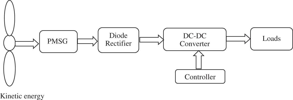
Figure 1: Block diagram of wind system
PMSG: In small-scale wind turbine generators, the PMSG mainly uses low mass and high power densities. Regulation of the stall and the pitch control located at the turbine hub is employed. Stall regulation shapes the blades that provide a lower aerodynamic force in the wind at high speed, which decreases the turbine torque, which is cost-effective and sturdy. Pitch control is used to adjust the torque control angle for optimized power capture and protection.
Wind energy system generates the AC three-phase power and transfers it to the rectifier to convert the AC–DC power. Although this is a hybrid solar and wind system, solar is a DC power output. The wind is an AC power output. So to coupling both energy and wind energy output has to convert with equal magnitude. The DC-DC boost converter is the purpose of the step-up of the voltage for the utility.
The amount of power (P) transferred is directly proportional to the air density (
Using the power available on the wind, the daily energy output of the wind generation can be calculated by Eq. (3).
2.2 Modelling of Solar PV System
The solar system is the conversion of sunlight into electricity by PV cells. This technology is very well recognized extensively in MGs. The PV output is given to the inverter, and AC power is given to the loads, the most common RES globally. The PV panels consist of solar cells, which are shown in Fig. 2.
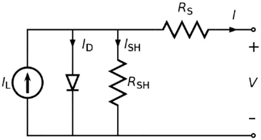
Figure 2: Equivalent circuit of PV cell
Iph = Photo–Current (A)
Rs = Intrinsic Shunt and Series Resistance (Ω)
ID = Diode Current (A)
Isc = Short Circuit current (A)
A= Surface area of the PV module m2
The mathematical modelling of the PV systems has been implemented in MATLAB and discussed below.
The solar cell output current
The current-voltage I-V characteristics are based on the PV module under a standard condition of Solar Irradiance G (t) = 1000 W/m2 and Temperature 25
3 Hybrid MG System Configuration
MGs are the best bulging network to extract the distribution of RES from the distributed grid, i.e., the electrical loads linked to the AC sides and used for electronic power systems. AC MGs are mainly utilized for protective reasons using conventional procedures. But RES involves converters, and the distributed sides of the grid termed the DC MG must be provided. There are further losses in each MG caused by a multiple power conversion. Thus, hybrid AC/DC MG is the most excellent approach to overcome the problem. The major aims of the AC/DC hybrid MG are to reduce the loss of conversion. This hybrid AC/DC MG is built with some techniques shown in Fig. 3.
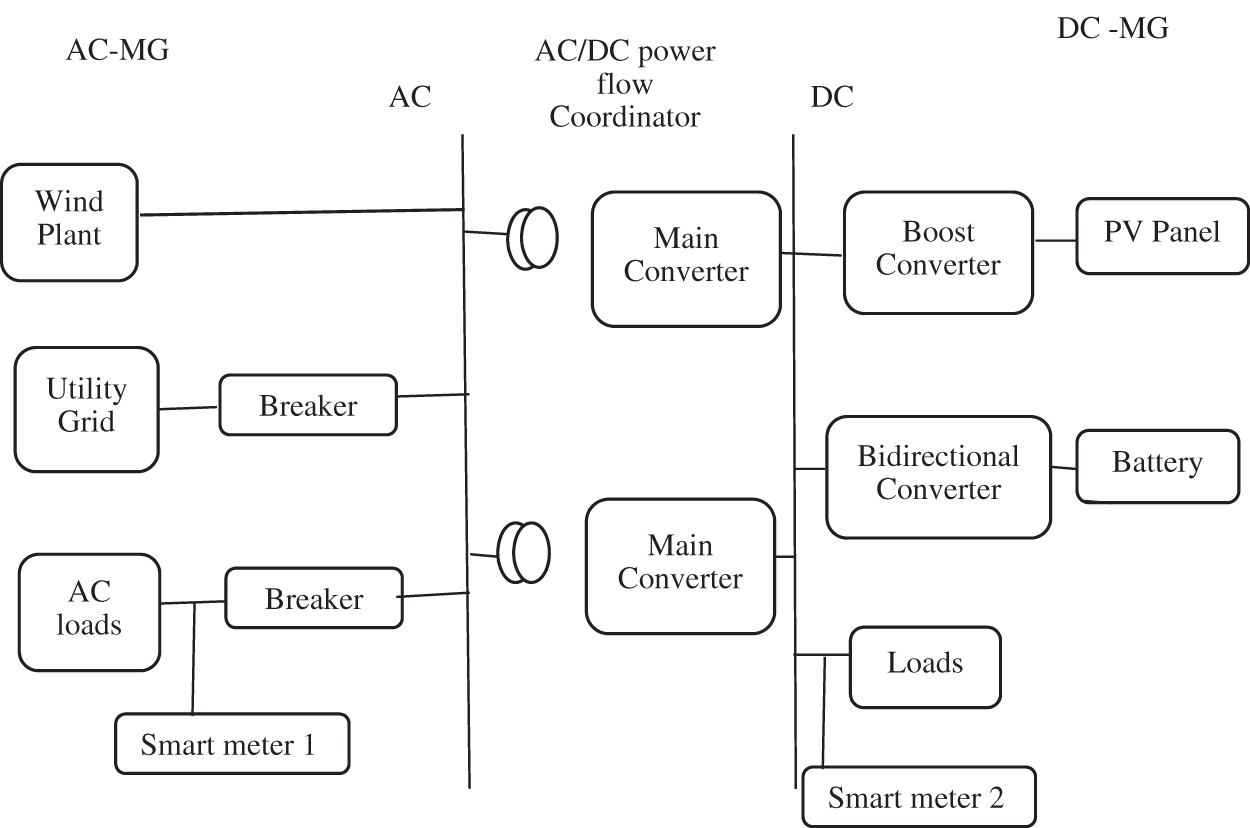
Figure 3: Hybrid AC/DC MG
The AC and DC buses are connected to the main converters, the transformer, and the hybrid grid AC buses. Converter plays a vital role when the hybrid MG is successfully operated. Conversion devices like inverter, buck/boost, and converters. Boost converters and inverters are primarily used here, compared to other typical converters, as the solar PV array requires an increase in low voltage to link the MG utilized to convert an AC power by an inverter. The expressions are illustrated below,
Energy charged by the battery is represented in Eqs. (10) and (11) represents that the supply the energy from the battery to load. Here using lithium ion battery with 12V and 300 Ah and initial state of charge is 100%. Where
Finally, the Eq. (12) illustrates that the total energy from the whole system.
The boost converter is used to step up the low voltage DC/DC converter. The PV is the main source in the MG. Thus, it is not appropriate for load feeding because the DC low voltage cannot meet load and grid needs through step-up voltage. Since, it has many advantages, there are (1) It provides high output voltages, (2) It offers lower operating duty cycle, (3) Cost effective, and (4) Lower voltage on MOSFET. In two-mode modes, this boost converter is provided. MOSFET is act as a switch (s) in Fig. 4.
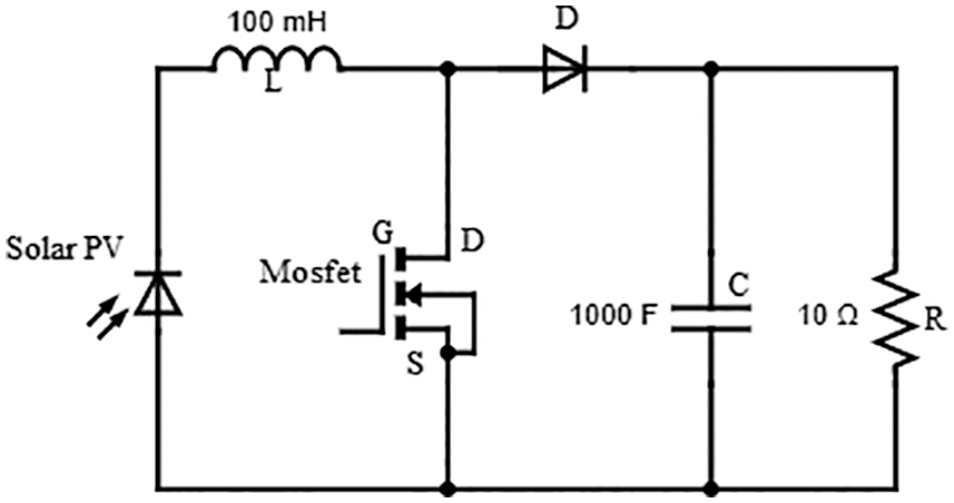
Figure 4: Boost converter
When the switch (S) is closed, the energy is store in an inductor. Hence the diode (D) is off the capacitor is blocked from the supply (Vs). When the Switch (S) is opened, the inductance is operated to supply the voltage to the load through the diode (D).
A bidirectional converter can flow the power in both directions. The purpose of this converter is to feed to the load and feed the power back to the source that can be shown in Fig. 5. So that this converter can be used in battery-connected solar systems which would requires bidirectional power flow. It can charge the energy from the solar PV and supply the power continuously to the load. Also it has some merits such as: High efficiency, low cost and compact size. Hence, the battery will deliver the stored energy to the loads during the night, directly connected to the solar PV.
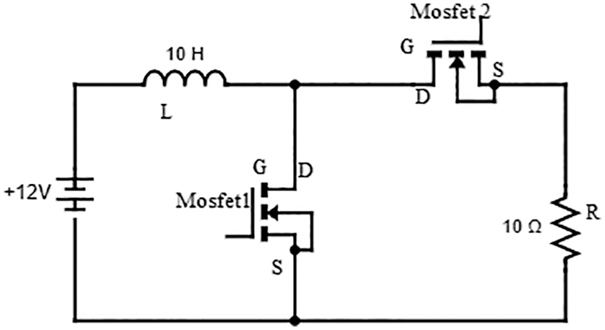
Figure 5: Bidirectional DC-DC converter
The inverter is used to convert the DC to AC which is the essential power electronic device. This can fix the solar PV and battery’s frequency, input voltage, output voltage, and output power.
where, the
Smart meters are more interactive with multi functionalities, and then they can record electricity usage by consumers. Also, communicate the information between consumers and suppliers through wireless networks. This smart meter particularly makes the home energy management systems for monitoring energy consumption. Also, every residential load can be recorded by the smart meter, which monitors the energy consumption by houses. This may be used to predict the future energy consumption of loads and is most accurate, which reduces the chances of error in the existing billing system.
MPPT technique is a circuit that is commonly used in the wind energy system and solar PV system. The solar PV’s operating point will rarely reach peak power when the load is connected with solar PV. By varying the impedance of PV, the operating point will reach peak power point. Hence the solar PV are DC devices, so a DC-DC converter connects with the load. This converter can change the duty ratio that results shows peak power point. Due to atmospheric conditions like irradiance and temperature, the power-voltage (P-V) curve can vary considerably in Fig. 6.
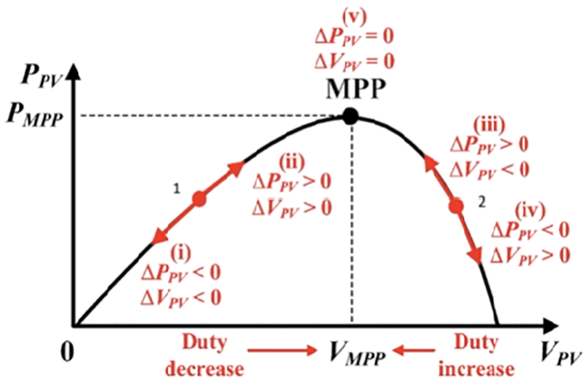
Figure 6: MPPT P-V curve
MPPT technique is used to optimize the output power of the solar PV. This can be classified into two strategies. There are Perturb and Observe (P&O), and incremental conductance.
In this work, we presented a P&O technique. This controller adjusts the small amount of the voltage and power from the solar PV. Further, the power increases then the controller adjusts the direction until the power no longer increases. That algorithm is shown in Fig. 7.
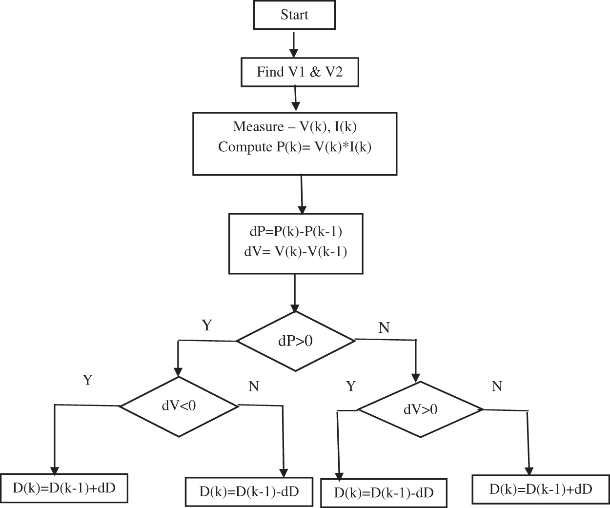
Figure 7: P & O algorithm
4.3 MPPT Control for Wind with PMSG
Nowadays, PMSG is commonly used because of its high efficiency, high power density, and economical. Low wears and tears, compact, low noise, and low maintenance cost can be realizable. WECS commonly converts variable frequency and voltage to fixed frequency and voltage, though using power electronic devices suitable for MPPT controller which consists of the torque references, discrete 1st order filter, PI controller, switches and PWM.
Here, this filter is used to remove the loss-harmonics and twinkle/flickers from the output of the inverter, which is coupled to the main power system. The parameters rating of L is 30 e−3 and C is 3000 e−6.
VSC are used to maintain the output voltage constant during load variations. VSCs’ primary function is to convert the DC voltage stored in a capacitor into AC voltages or AC voltages into DC voltages. One of the benefits of VSCs is that they allow you to regulate the active and reactive power flows with an ac-grid independently. This converter can is suitable for high-power electronic devices like insulated-gate bipolar transistor. This is suitable to inject real and reactive power into the MG. VSC is usually fed to DC power sources, which are integrated with the grid. This operation is set the voltage and frequency for the isolation mode of the MG. Hence the capacitor and inductor connected to the converter decide the VSC dynamic operation. Change in loads resembles change in frequency and voltages in the grid. Moreover, the decreasing voltage with increasing reactive power and increasing real power with decreasing frequency may be compensated by VSC.
Here, addresses to employ an optimal PID controller for frequency regulation of MG system, the main issues are tuning the optimal values to solve by GA through an objective function [18]. PID tuned GA controller automatically specified with objective functions, which is formulated and calculate the controller’s performance in terms of time-domain bounds on the response of closed-loop. A GA (shown in Fig. 8) has enhanced the appearance of the computer system and works without detail. It depends on the evolutionary operators’ reactions such as reproduction, cross-over, and mutation. Within a GA, the issue is investigated and initialized by population, development, exercise measurement, population fitness selection, and reproduction and provides the best solution fitness.
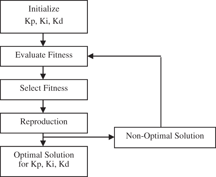
Figure 8: Flow chart of GA
4.7 PID Controller Optimization by GA
Mainly PID controller is used to reducing the error signal. In many industrial applications, the PID controller is utilized because it is effective and simple. This model is designed using three-term control, shown in the transfer function (Eq. (16)) of this implemented system.
where KP is the proportional gain, KI is integral gain, and KD is the derivative gain. PID control aims to set the Kp, Ki, Kd parameters to satisfy a certain set point for the performance of closing loop systems. The objective function (J) considers the optimization problem operates the variables of PID control shown in Eq. (17).
The Integral Time Absolute Error (ITAE) in Eq. (17) is an error value used to calculate the output for a closed-loop system. In this work, using the transfer function, the delay range is between 0.01 and 1sec. This optimized PID controller is mentioned in the above section; the objective function is also programmed as in MATLAB’s M-file. This programmed objective function is applied to the GA toolbox in M-file and runs the GA to optimize the PID, which gives the best values of an objective function.
5 Simulation and Result Discussions of Smart Grid
The smart grid is designed and implemented using MATLAB/Simulink. This hybrid system is modelled by Simscape. It is carried out for the grid connection through transformer, which represents the parameters range such as phase to phase root mean square voltage (V) which is 25 e3V with 50 Hz, then two winding three-phase transformer range (250 e6VA) and the solar PV and wind power generation in output power. The performance analysis of the designed system is discussed by analyzing the solar irradiation, temperature of the solar panel, wind speed, and wind direction are getting accurate results. Generally, the system performance should be analyzed for the one-day load flow of the smart grid. Further, the output characteristics of every stage like a solar cell, battery, wind, and converter, energy consumption of residential loads of both DC and AC loads for one hour, and the output characteristics of the AC voltage and current of the loads are illustrated. Figs. 9 and 10 show the PV Vout without using MPPT technique and PV Isc respectively.
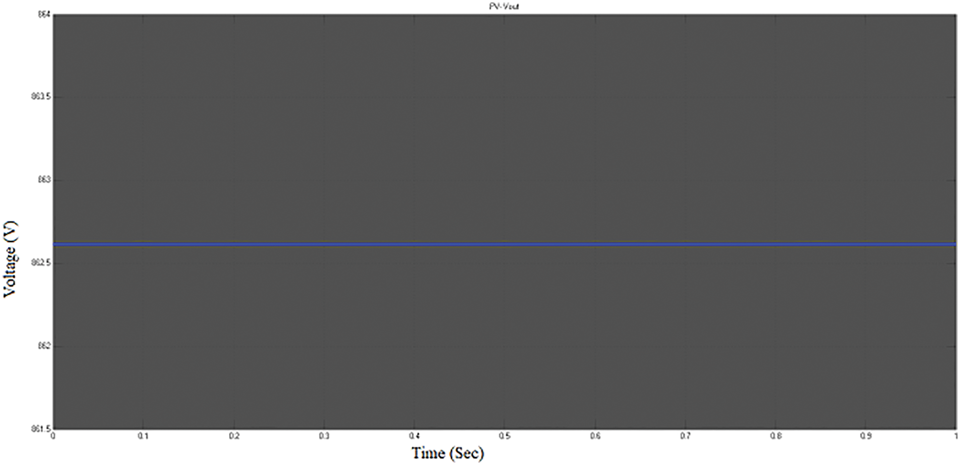
Figure 9: PV Vout without using MPPT technique
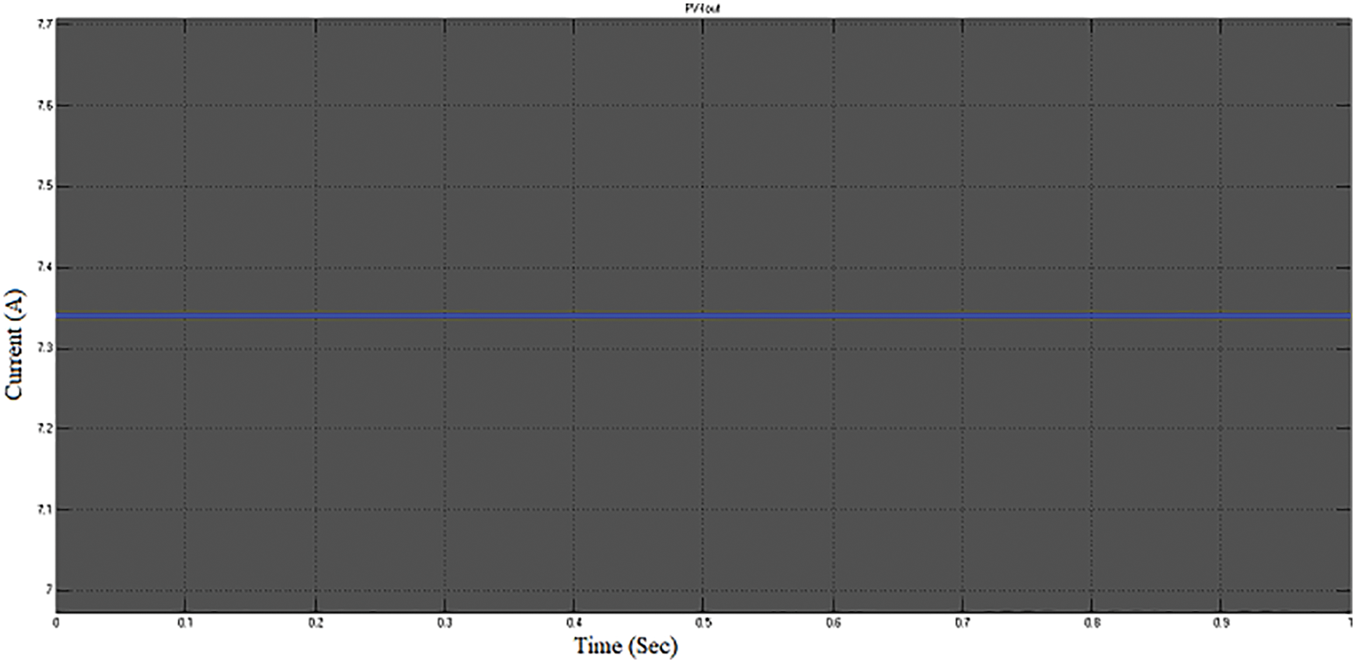
Figure 10: PV Isc
This waveform represents that the solar PV output voltage is 862 V, which is four modules; each module carries 72 solar cells at the rating of short circuit current (Isc) is 7.34 as shown in Fig. 10. And the open-circuit voltage is 3 V. When the irradiation is at 1000 W/m^2, and the temperature is at 25
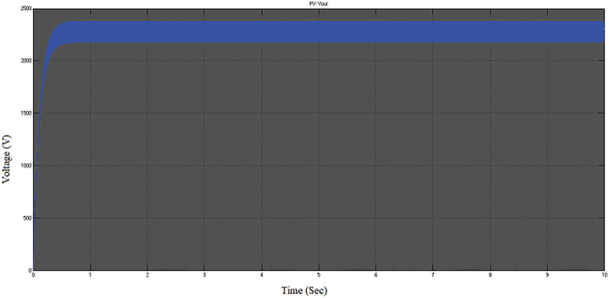
Figure 11: PV Vout
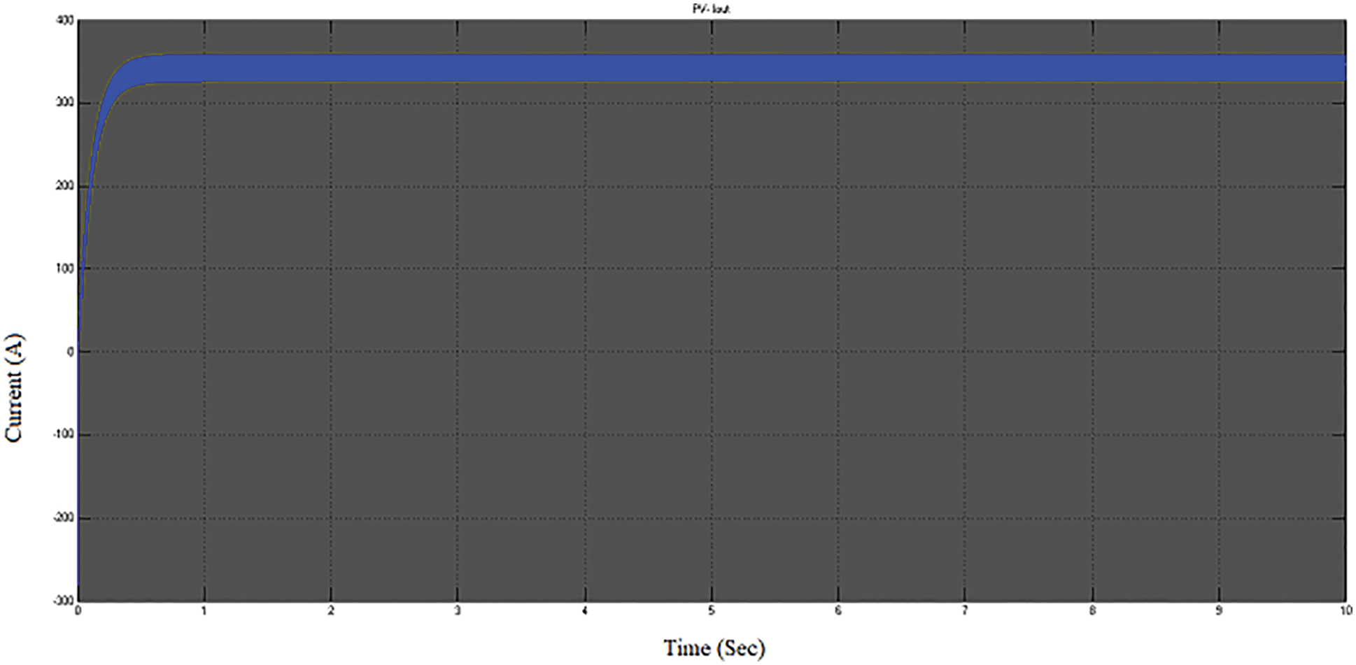
Figure 12: PV Iout
The boost converter is used with MPPT technique that can improve the output voltage and output current of the PV system which is 2.3 kV and 357 A, respectively. This output voltage is either given to the loads or the grid according to the customers’ preferences. The waveform in Fig. 13 represents the WECS’s output voltage and output current. The wind system’s output voltage (Vabc) is 40 kV, and the output current (Iabc) is 4000 A. This hybrid smart grid system is designed for one-day simulation. The 300 Ah capacity of the battery is incorporated with the PV system, which is designed based on the current source and load current by the input power. This battery reaches 176 V, and the peak value of the battery voltage should vary corresponding to the load demand and stabilize in the rating as mentioned above, shown in Fig. 14.
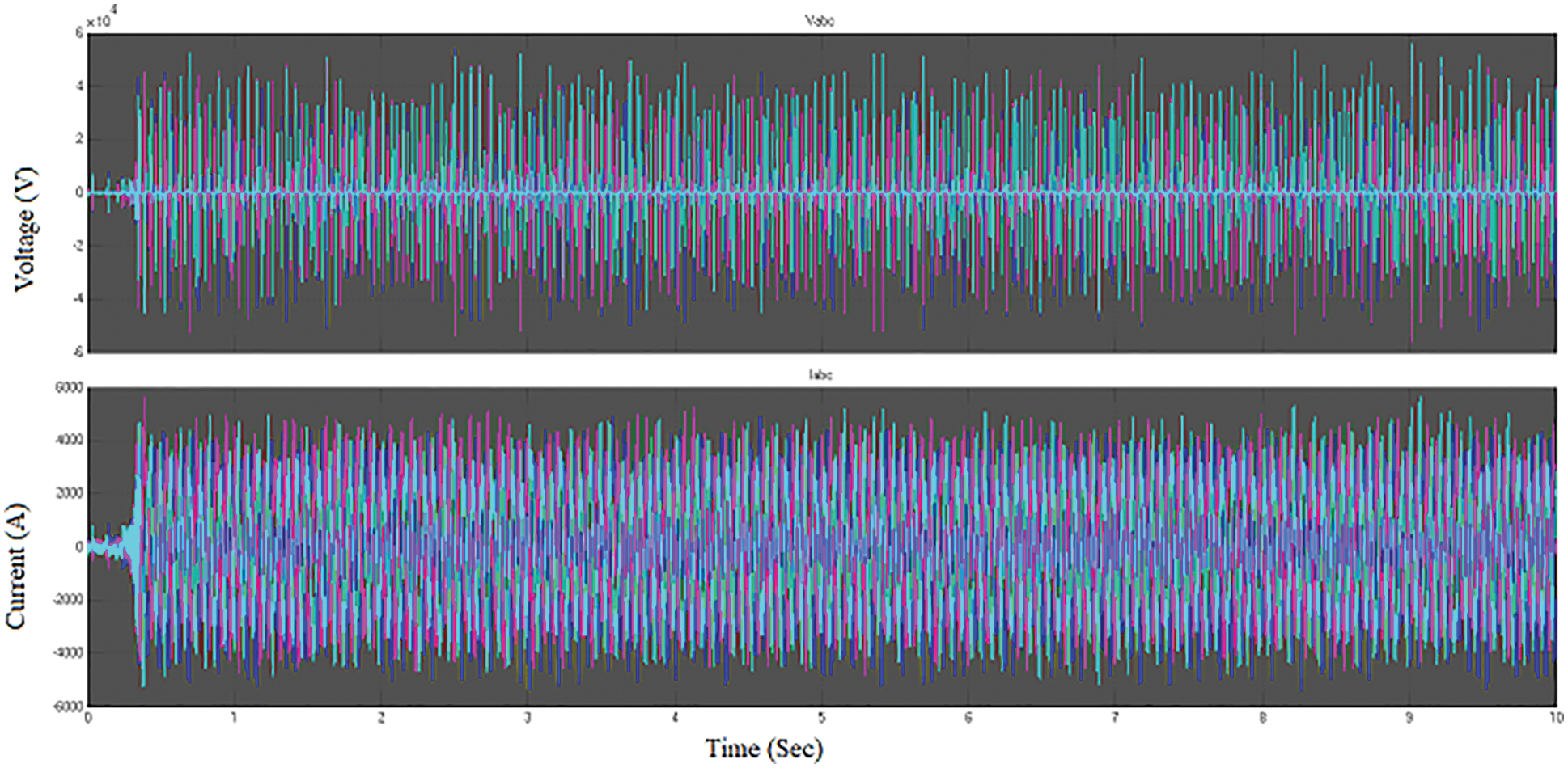
Figure 13: WECS output voltage and output current
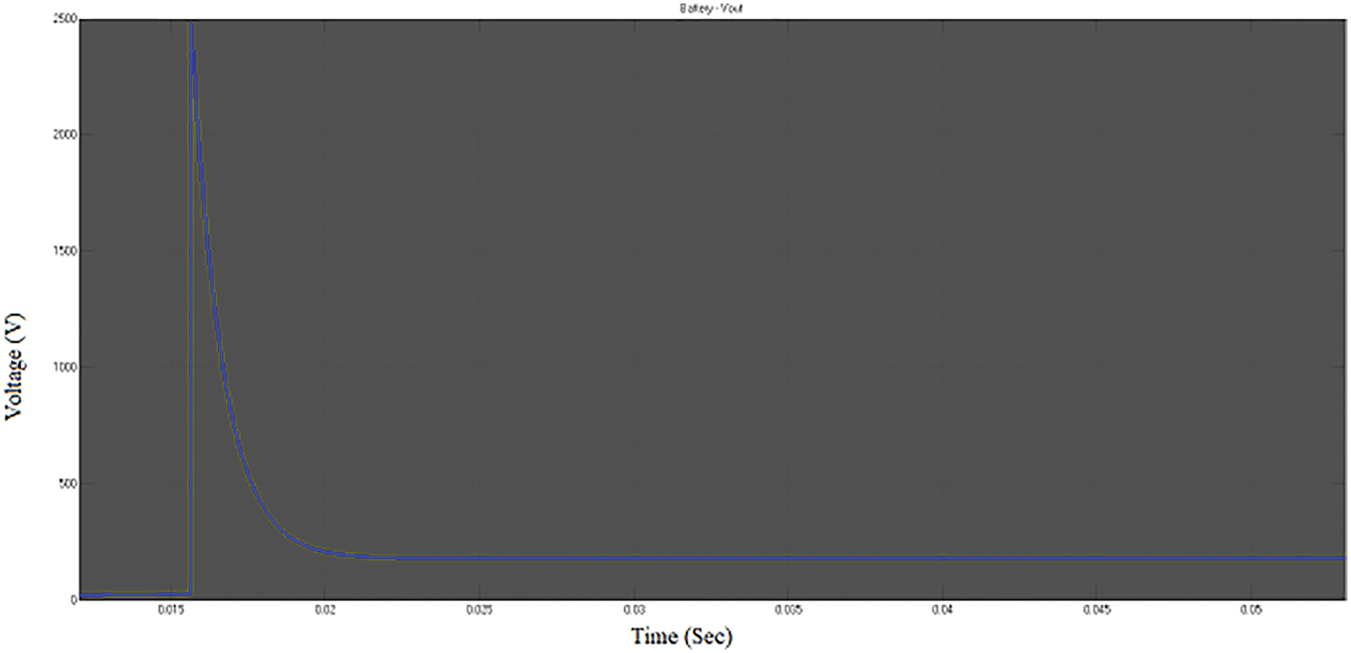
Figure 14: Battery Vout
Fig. 15 represents the main converter AC load voltage and current, showing the 300 V and the frequency is 50 Hz. This Vac is 300 peak with 20 Inc, synchronized with the grid, obtained at the inverter output.
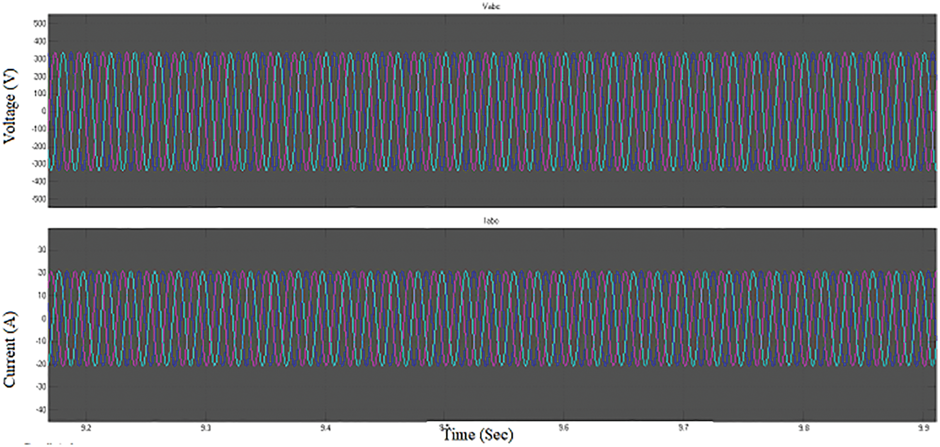
Figure 15: Main converter AC voltage and current
Fig. 16 shows that the AC load voltage and AC load current are connected to the grid. This represents the load which is the same as the main converter AC voltage and current. This Voltage range is 320 V, and the current value is 150 A. This waveform represents that the voltage and currents are Distributed generation (DG) load voltage and load current, the voltage is 20 V, and the current is 10 A. These loads are considered the residential loads taken from the DG, which shows the Fig. 17.Also, the real power (P) and Reactive power (Q) can be shown in Fig. 18. The P is 5 kV, and the Q is 9 kV.
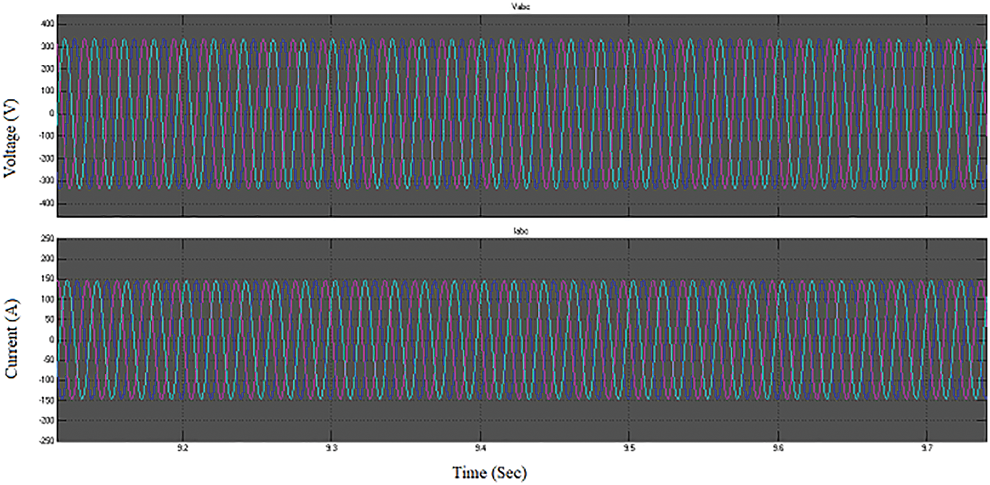
Figure 16: AC load voltage (VL) and current (IL)
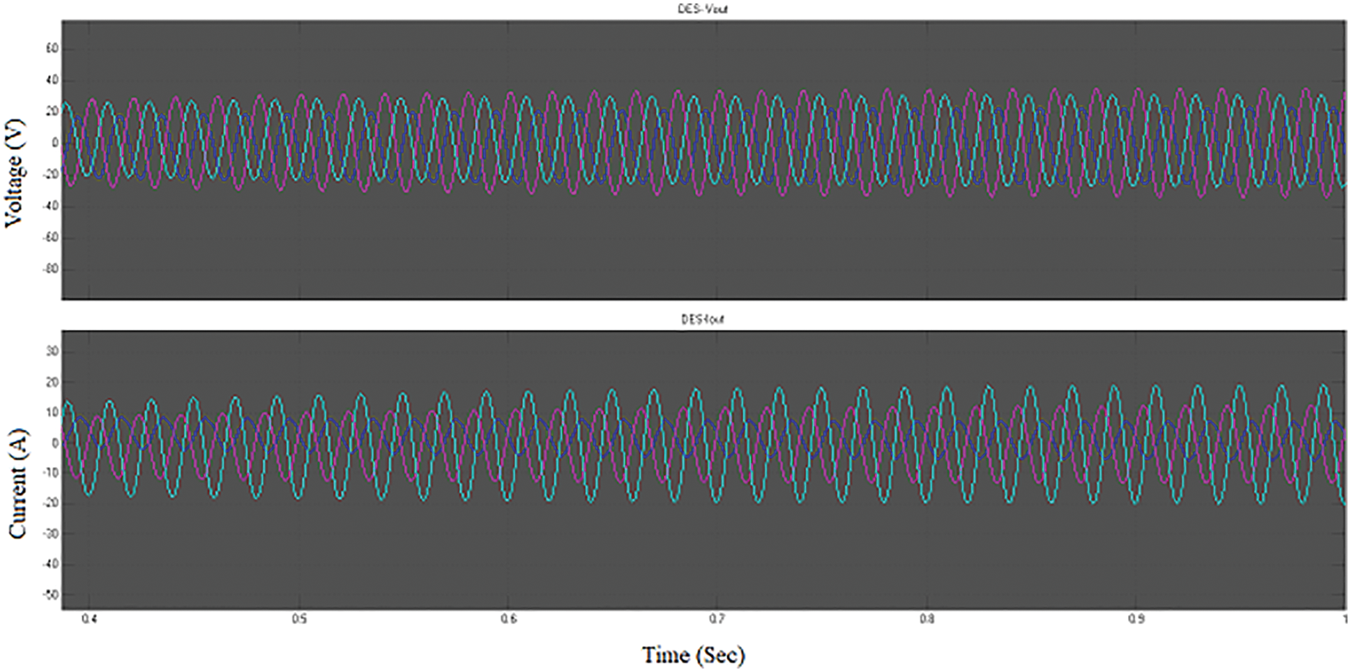
Figure 17: DES Vout and Iout
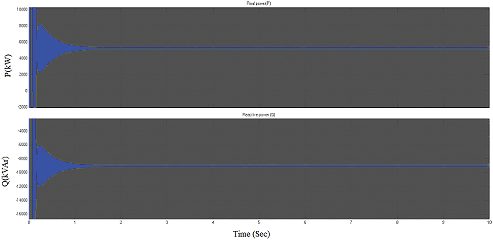
Figure 18: Real power and Reactive power of MG
Fig. 19 represent the Power factor (PF) which is 0.6. In general, low factor (0.6 to 0.7) occurs in the industrial sector where the bulk of the load is inductive; thus, it is mandated that all such firms use synchronous motors to enhance power factor.
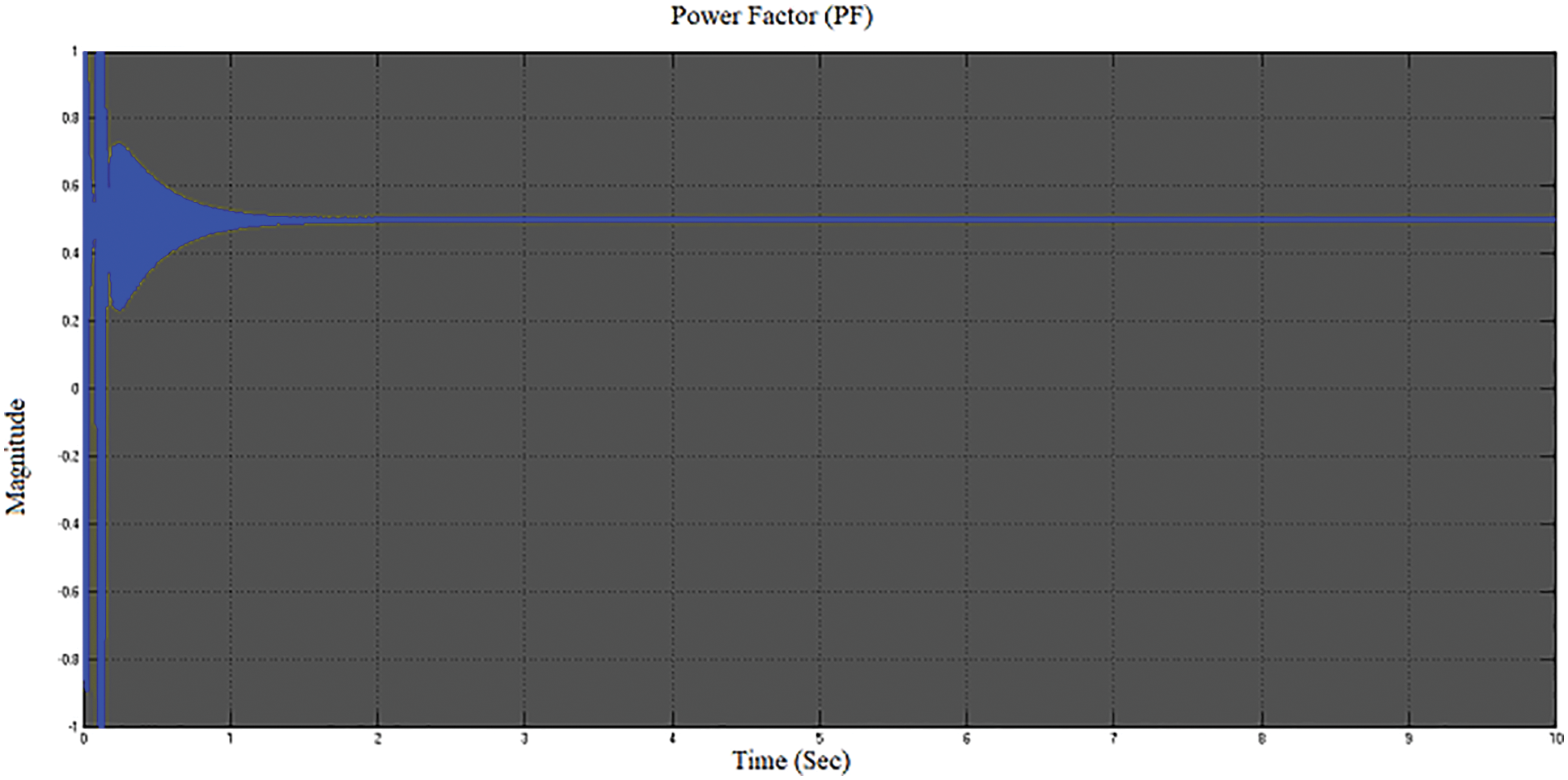
Figure 19: Power factor of MG
Fig. 20 illustrates that the energy consumption of DC loads which is measure by a smart meter. This represents the hourly-based consumption of the DC side loads, increasing for time(s) meanwhile raising the energy consumption from 0 to 0.05 KWh. Fig. 21 illustrates the AC side loads, which consume the energy 0.033 KWh at 0.1 to 1 s.
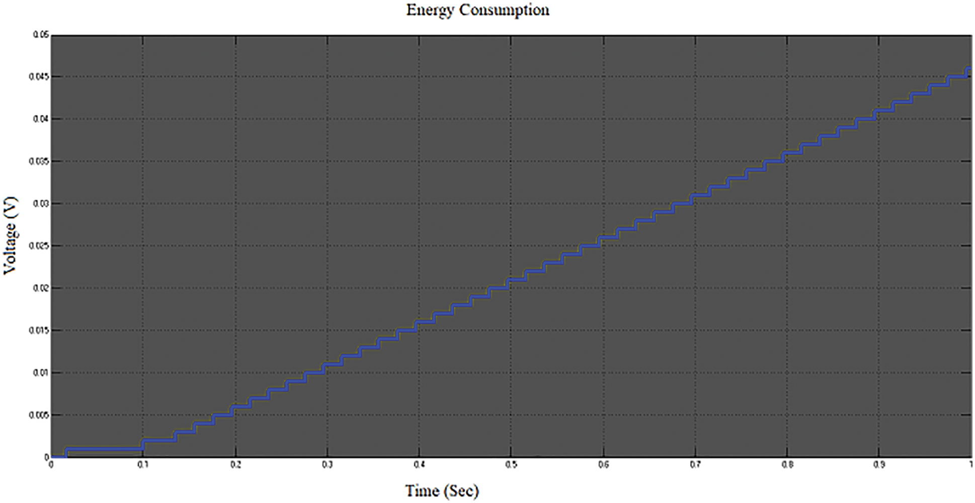
Figure 20: Energy consumption of DC side residential loads
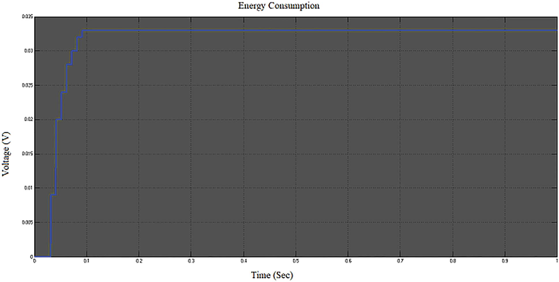
Figure 21: Energy consumption of AC side residential loads
Fig. 22a represents the step response of the optimized PID-GA of objective functions; this step response is the time behaviour of the system’s output when the input changes from 0 to 1 in a short time. This waveform shows this is a first-order process, where the gain is 2, and the time constant is 1, and the system is settled at 10 s. Fig. 22b shows that the best fitness function from the generations, The fitness value of an individual is the value of the fitness function for that individual. Because the toolbox programme determines the minimum of the fitness function, the best fitness value for a population is the minimal fitness value for any individual in the population. Then the best fitness value is 0.00827242, and the mean fitness value is 0.00827272.
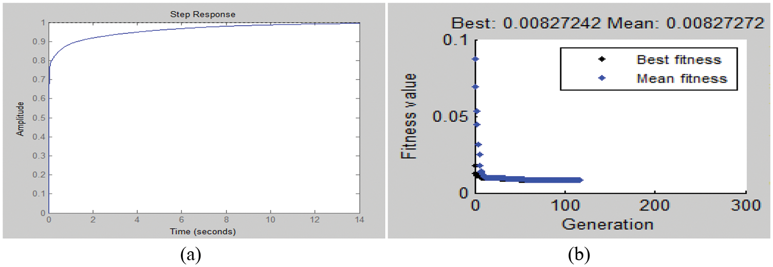
Figure 22: (a) Step response (b) Generations
Fig. 23a shows the best individuals among the 3 variables and Fig. 23b illustrates the selection function from the individuals and children.
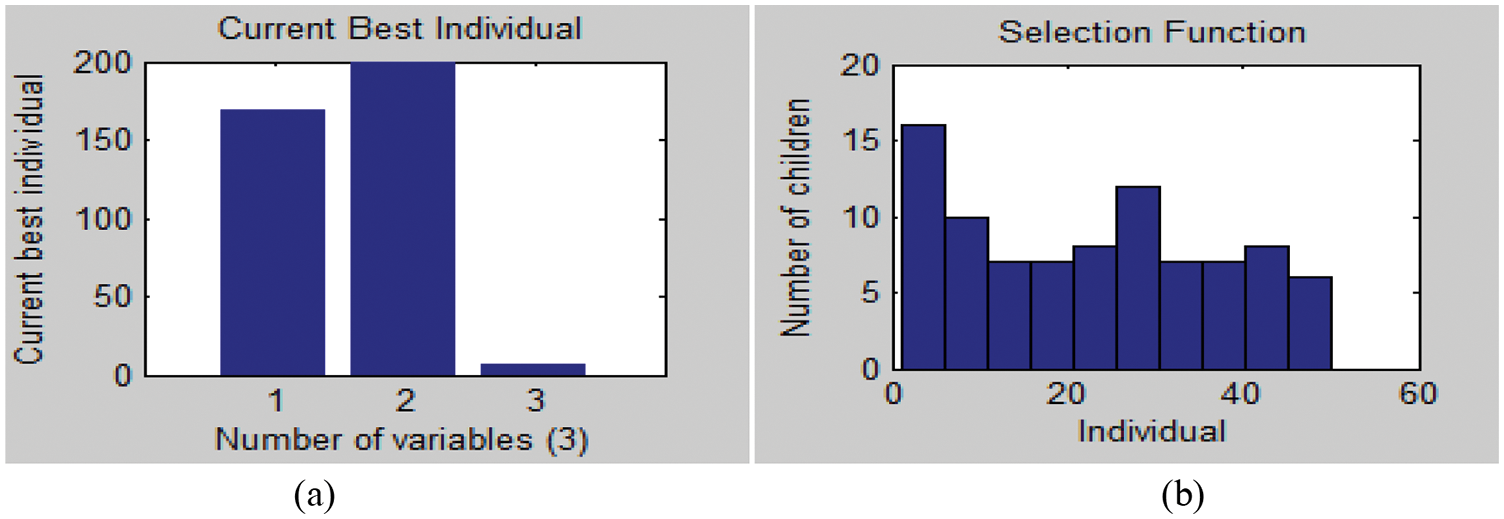
Figure 23: (a) Best individuals (b) Selection function
Fig. 24 represents the Total Harmonic Distortion (THD) of the implemented system, a distributed renewable energy source using PID tuned GA. According to the IEEE standards, the THD value must be less than 5%. By proposed method in the implemented system shows that THD is 4.87%.
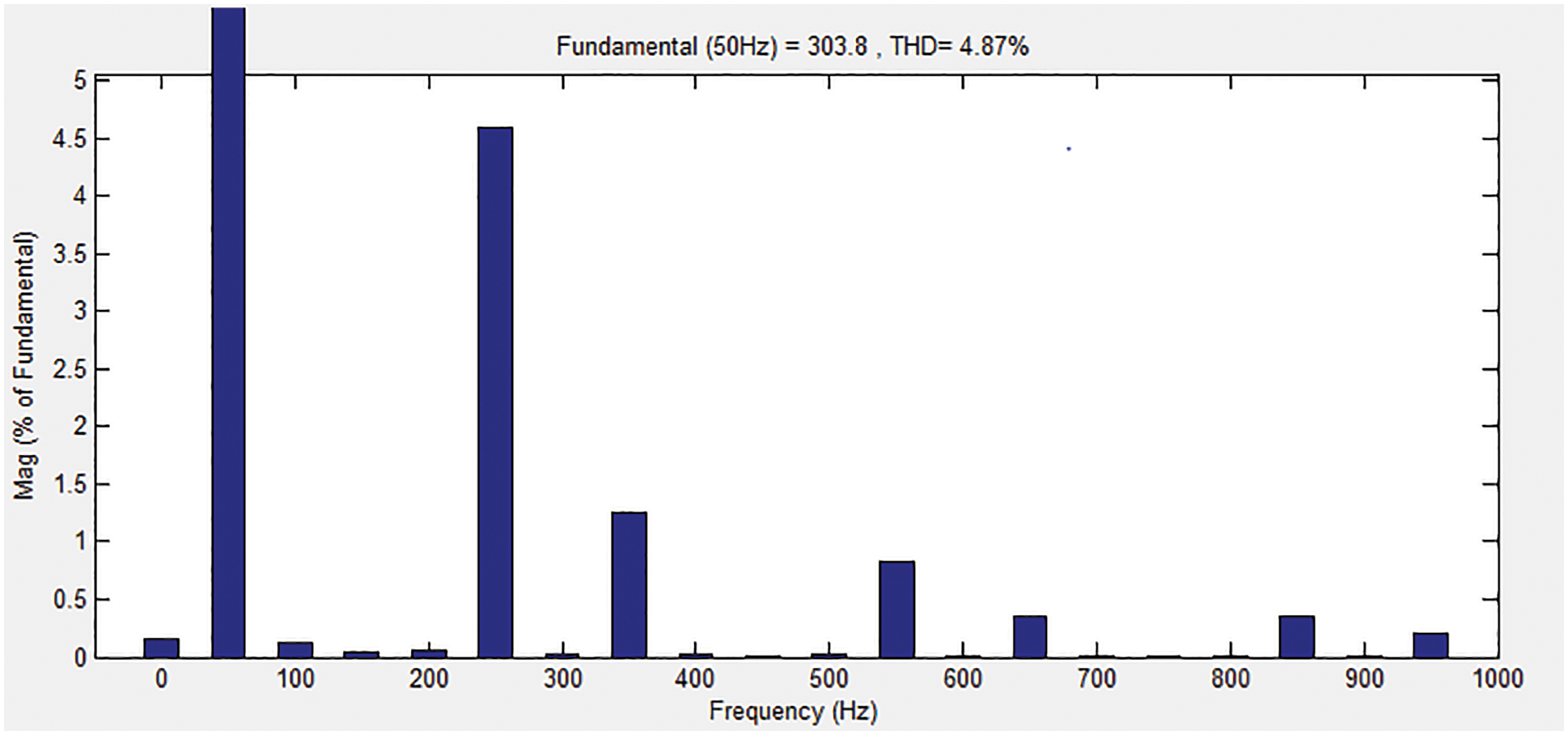
Figure 24: THD of the implemented system
The parameters of the hybrid MG system are summarized in Tab. 1.
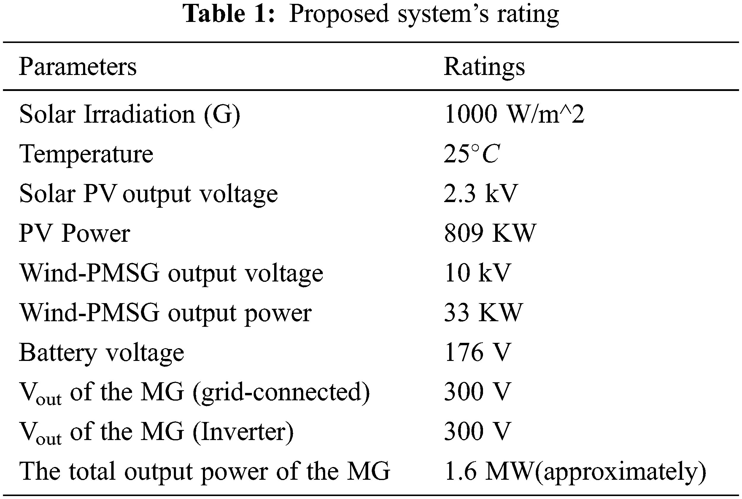
An implemented smart grid is approximately 1.6 MW capacity which has been operating in grid-connected and isolated mode conditions. Also, this implemented smart grid can reduce energy costs and increase reliability. This distributed energy source system is more attractive because it is green energy, eco-friendly, and pollution-free. The modern design quickly adapts to the alterations. This system also supplies power to the existing transmission and distribution system. Mainly, the MG is an excellent power extractor from distributed generation, which operates in both modes. Moreover, the system can operate the source to transfer the maximum power. The implementations of data communication and controlling techniques make the hybrid MG called as ‘smart grid.’ PID tuned GA can operate these implemented systems to solve the optimization problems based on the natural selection process, which can also reduce the THD%. This represents that the system has low harmonic distortion according to the IEEE standards also this system has more effective than the existing system in the sense of stability and reliability. This implemented hybrid MG system acted as a smart grid and faced power quality issues. In future, to rectify this issue, FACTS devices can be used to improve the power quality using various techniques. Several approaches are utilized to enhance power quality in MGs. To increase the power quality in MGs, several strategies in the current and voltage control strategy for VSI are adopted utilizing time domain controllers. Shunt and series compensators are used in three phase four wire or three-phase three wire compensators to regulate voltage imbalance and current.
Funding Statement: The authors received no specific funding for this study.
Conflicts of Interest: The authors declare that they have no conflicts of interest to report regarding the present study.
References
1. S. Chandak and P. K. Rout, “The implementation framework of a microgrid: A review,” International Journal of Energy Research, vol. 45, no. 3, pp. 1–25, 2020. [Google Scholar]
2. N. Kannan, “Microgrid”, in Research Trends and Challenges in Smart Grids, 1st ed., London, UK: IntechOpen, Chapter No. 6, pp. 112–137, 2020. [Google Scholar]
3. F. R. Badal, P. Das, S. K. Sarker and S. K. Das, “A survey on control issues in renewable energy integration and microgrid,” Protection Control of Modern Power Systems, vol. 4, no. 8, pp. 1–27, 2019. [Google Scholar]
4. E. Kabalci, H. Irgan and Y. Y. Kabalci, “Hybrid microgrid system design with renewable energy sources,” in IEEE 18th Int. Power Electronics and Motion Control Conf., Budapest, Hungary pp. 387–392, 2018. [Google Scholar]
5. A. Alzahrani, M. Ferdowsi, P. Shamsi and C. H. Dagli, “Modeling and simulation of microgrid,” Procedia Computer Science, vol. 114, pp. 392–400, 2017. [Google Scholar]
6. Y. ToghaniHolari, S. A.Taher and M. Mehrasa, “Distributed energy storage system based nonlinear control strategy for hybrid microgrid power management included wind/PV units in grid connected operation,” International Transaction on Electrical Energy Systems, vol. 30, no. 2, pp. 1–20, 2019. [Google Scholar]
7. A. Ignat, E. Szilagyi and D. Petreus, “Renewable energy microgrid model using Matlab-Simulink,” in 43rd International Spring Seminar on Electronics Technology, Demanovska Valley, Slovakia pp. 1–6, 2020. [Google Scholar]
8. R. Chowdhury and T. Boruah, “Design of a micro-grid system in Matlab/Simulink,” International Journal of Innovative Research in Science, Engineering and Technology, vol. 4, no. 7, pp. 5262–5269, 2015. [Google Scholar]
9. Y. B. Aemro, P. Moura, T. Aníbal and de Almeida, “Modeling of a standalone DC-microgrid for off-grid schools in rural areas of developing countries,” Energies, vol. 13, no. 23, pp. 1–24, 2020. [Google Scholar]
10. M. S. Mahmoud, S. A. Hussain and M. A. Abido, “Modeling and control of microgrid: An overview,” Journal of the Franklin Institute, vol. 351, no. 5, pp. 2822–2859, 2014. [Google Scholar]
11. K. Tazi, F. Abbou, M. Bannour Chaka and F. Abdi, “Modeling and simulation of a residential microgrid supplied with PV/batteries in connected/disconnected modes-case of Morocco,” Journal of Renewable and Sustainable Energy, vol. 9, no. 2, pp. 1–16, 2017. [Google Scholar]
12. O. Apata and D. T. O. Oyedokun, “An overview of control techniques for wind turbine systems,” Scientific African, vol. 10, no. 1, pp. 1–13, 2020. [Google Scholar]
13. N. Manie and B. Pattanaik, “Zeta DC-DC converter based on MPPT technique for BLDC application,” International Journal of MC Square Scientific Research, vol. 11, no. 2, pp. 1–11, 2019. [Google Scholar]
14. O. Zebraouiand and M. Bouzi, “Comparative study of different MPPT methods for wind energy conversion system,” International Conference on Renewable Energies and Energy Efficiency, vol. 161, pp. 1–10, 2018. [Google Scholar]
15. M. Hu, F. Xiao and S. Wang, “Neighborhood-level coordination and negotiation techniques for managing demand-side flexibility in residential microgrids,” Renewable and Sustainable Energy Reviews, vol. 135, pp. 110–248, 2021. [Google Scholar]
16. B. Chetry, A. Carvalho and R. Brito, “Voltage source converter in a microgrid,” International Journal of System Assurance Engineering and Management, vol. 9, pp. 1206–1216, 2019. [Google Scholar]
17. N. H. Azmi, N. A. Mat Leh and N. A. Kamaruzaman, “Modeling of energy meter using MATLAB/Simulink,” in 9th IEEE Control and System Graduate Research Colloquium, Shah Alam, Malaysia pp. 75–80, 2018. [Google Scholar]
18. A. Gupta, R. P. Saini and M. P. Sharma, “Modeling of the hybrid energy system-Part I: Problem formulation and model development,” Renewable Energy, vol. 36, no. 2, pp. 459–465, 2011. [Google Scholar]
19. A. Singh and Sathans, “GA optimized PID controller for frequency regulation in standalone AC microgrid,” in India Int. Conf. on Power Electronics, Patiala, India pp. 1–5, 2016. [Google Scholar]
Cite This Article
 Copyright © 2023 The Author(s). Published by Tech Science Press.
This work is licensed under a Creative Commons Attribution 4.0 International License , which permits unrestricted use, distribution, and reproduction in any medium, provided the original work is properly cited.
 Downloads
 Citation Tools